Assembly and operating instructions
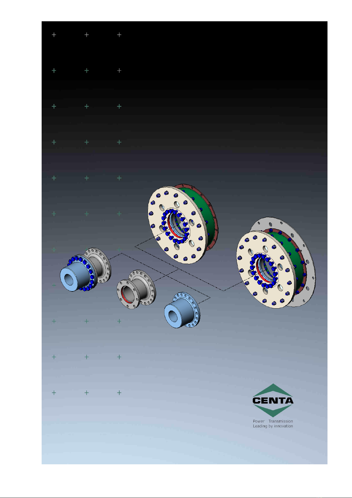
CENTAX-N
033N-00035…00075-F.00
CENTA Antriebe Kirschey GmbH 2 / 47
Contents
1General remarks ..................................................................................... 5
2Safety ..................................................................................................... 6
2.1 Safety remarks.................................................................................. 6
2.1.1 Signal words ......................................................................... 6
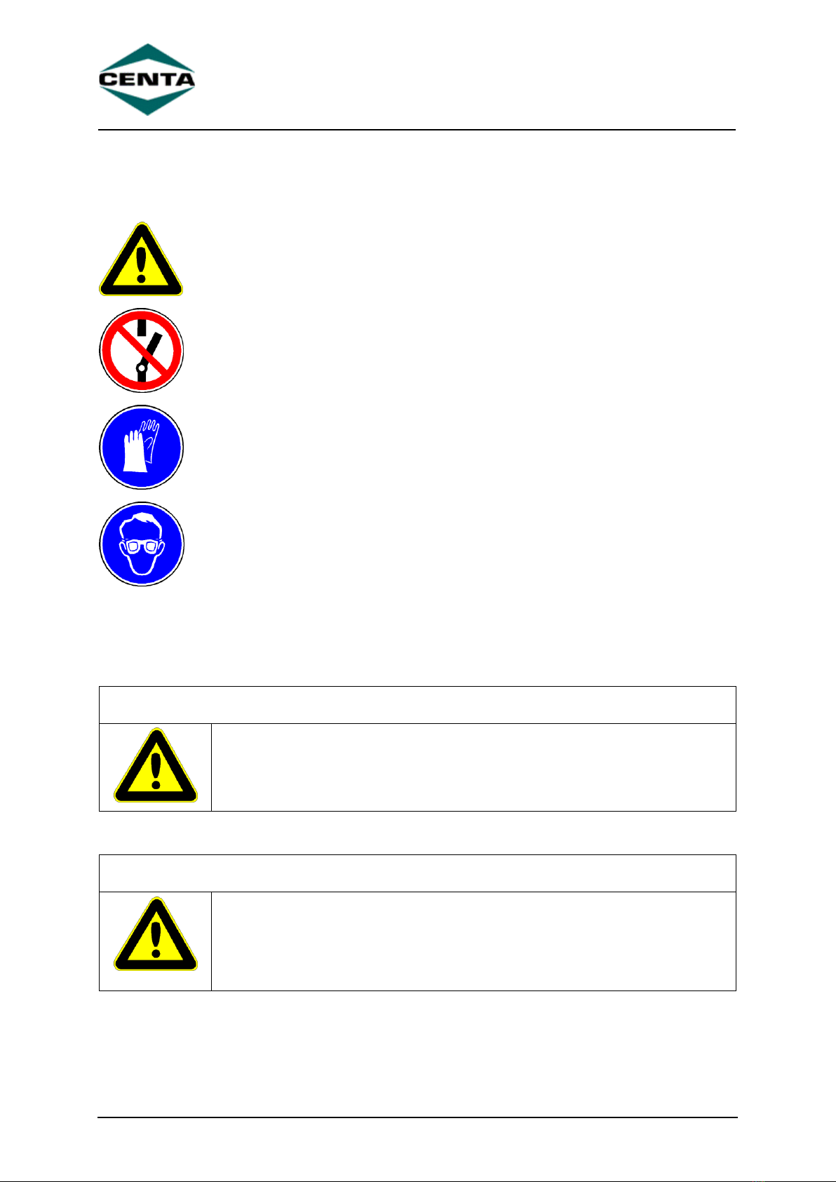
2.1.2 Pictograms ............................................................................ 7
2.2 Qualification of deployed personnel ...................................................... 7
2.3 Intended application........................................................................... 7
2.4 Application not in compliance with the intended use ............................... 9
3Delivery, transport, storage and disposal ............................................. 10
3.1 Delivery...........................................................................................10
3.2 Transport.........................................................................................10
3.3 Storage ...........................................................................................10
3.3.1 Storage location....................................................................11
3.3.2 Storage of couplings / flexible elements ...................................11
3.4 Disposal...........................................................................................11
4Technical Description............................................................................ 12
4.1 Characteristics..................................................................................12
4.2 Specifications ...................................................................................12
5Alignment of the units being connected................................................ 13
5.1 Axial alignment.................................................................................14
5.2 Radial alignment...............................................................................16
5.3 Angular alignment.............................................................................18
6Mounting .............................................................................................. 20
6.1 General assembly instructions ............................................................20
6.2 Sequence of mounting.......................................................................22
6.3 Mounting the hub (if necessary) .........................................................24
6.3.1 Mounting the hub with keyway ...............................................24
6.3.2 Mounting the hub with conical oil interference fit.......................26
6.3.3 Mounting the CENTA-conical clamping hub ...............................29
6.4 Mounting the adapter (10; if necessary) ..............................................31
6.5 Aligning the units..............................................................................31
6.6 Mounting the pre-mounted rubber element assembly (C/D) to the
flywheel...........................................................................................32
6.6.1 Mounting the pre-mounted rubber element assembly (C) and
sheet to the flywheel .............................................................32
6.6.2 Mounting the pre-mounted rubber element assembly (D) with
adapter to the flywheel ..........................................................34
6.7 Mounting the adapter (1.4) ................................................................36