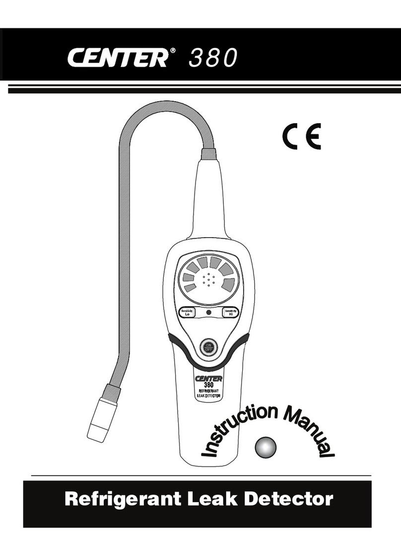
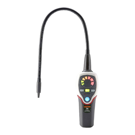
Center 389 User manual

389
Carbon Dioxide Leak Detector

CONTENT Page
1. GENERAL INFORMATION ------------------2
2. FEATURES
-----------------------------------------2
3. SPECIFICATIONS
-------------------------------3
4. OPERATION GUIDE ---------------------------4
5. PART & CONTROL------------------------------5
6. GETTING STARTED----------------------------7
6-1 Installing Battery--------------------------------7
6-2 Charging -----------------------------------------7
6-3 Lithium-ion Battery Care ---------------------8
7. OPERATING PROCEDURE----------------12
8. CLEANING
----------------------------------------16

CO2Leak Detector
2
1. GENERAL INFORMATION
Thank you for purchasing CO2Refrigerant Leak
Detector. Read through the instruction manual before
operation for correct and safe usage. Please store
and retain this instruction manual for future reference.
2. FEATURES
CO2Refrigerant Leakage Detector uses a newly
developed optical gas sensor which is extremely
sensitive to a variety of R744 refrigerant. It provides
features of fast-response, high-reliability, and
long-durability. It is an ideal tool for maintaining
industrial heat extraction, heat pump water heaters,
chilled warehousing, supermarkets, shopping vessels,
commercial refrigeration and automotive air
conditioning.
Microprocessor Control with advanced digital
signal processing.
Multi-color visual display.
Mute function to turn off audible alarm.
High-Medium-Low leak sensitivity selector.
Low battery indication.
Optical gas sensor.
Detection gas: R744 (CO2).
Carrying case included.
15.5” (40 CM) flexible stainless probe.
Ambient concentration reset.
Peak function – find leaks in noisy environments.

CO2Leak Detector
3
Automatic zero and background compensation.
AC Adapter: @5V 1A
3. SPECIFICATIONS
Detectable Gas: R744 (CO2)
Sensitivity:
H M L
R744 6g/year 15g/year 30g/year
Alarm Method:
Buzzer, Tricolor LED bar Indicator
Power Usage:
3.7Vdc rechargeable Lithium-ion battery
Snake Tube Length: 40cm ( 15.5” )
Dimension / Weight:
222 x 66 x 51 mm ( approximately 418g )
Accessories:
User manual, carrying case, AC adapter, Li-ion battery
pack
Battery Life:
Approximately 12 hours under normal use
Auto Power OFF: 10 minutes
Warm-Up Time: Approximately 45 seconds
Operating Temperature & Humidity:
0 ~ 40°C, < 80% RH

CO2Leak Detector
4
Storage Temperature & Humidity:
-10 ~ 60°C, < 70% RH
Altitude: < 2000M (6500’)
4. OPERATION GUIDE
(1) The (CO2) Leak Detector unit is not equipped with
anti-explosive designs and measures. Do not use
this unit in the environment with the burnable
gases.
(2) There are some environmental conditions that
might cause error reading:
Pollutant places.
Large temperature variation.
Places with high wind velocity.
Organic solvent, adhesive vapor, fuel gas and
vesicant will cause abnormal response from the
sensor. Try to avoid the environment involved
with this substance.
Places fill with high concentration of R744 gas.

CO2Leak Detector
5
5. PARTS & CONTROL
5-1 Panel Description

CO2Leak Detector
6
○
1Sensor Probe ○
2Sensor Protector
○
3LED Leak Indicators ○
4PEAK Button
○
5Sensitivity H/M/L
Button
○
6MUTE Button
○
7Low Battery Indicator
○
8Power On/Off
○
9Battery Cover ○
10 DC 5V Jack
5-2 LED Leak Indicator Definition:

CO2Leak Detector
7
6. GETTING STARTED
6-1 Installing Batteries
Loose the screw and remove the battery
compartment door located on the bottom of the
instrument as show below (Fig.1).
Install Lithium-ion battery pack.
Reinstall the battery cover by aligning it with the
handle.
When the battery power is low, the red LED low battery
indicator illuminates. The battery should be recharged
as quickly as possible.
6-2 Charging
When the battery is being charged, the power
indicating LED will be on. It will be off after charging is
completed.
During the charging period, if the power indicating LED
blinks, it may be caused by the following reasons.
(1) Charging period is too long and the detector is
sending the warning signal. Please disconnect the
power and try again later. If the situation remains,
the battery might need to be replaced.
(2) The temperature of the battery is too high for
charging operation. Disconnect the power and wait
until it cools down then try it again.
(3) This detector is using Lithium-ion rechargeable
battery and there will not be any charging memory

CO2Leak Detector
8
effect. Frequently charging routine after use is
recommended to avoid over discharging which
could damage the battery.
6-3 Lithium Battery Care
The Refrigerant Leak Detector contains a very
powerful Lithium-ion battery. For a long battery life and
safe operation, you must observe the following:
CAUTION!
(1) Do not short-circuit battery.
(2) Do not reverse connect.
(3) Do not dissemble or reconstruct battery.
(4) Do not expose the battery to temperatures higher
than 140°F (60°C).
(5) Do not charge the battery in or nearby heated
places, such as fire, hot vehicles, or direct sunlight.
(6) Do not expose the battery to direct impact or throw
it.
(7) Do not get the battery wet.
(8) Do not deform or pierce the battery in any way.
(9) If there is any battery leakage, do not touch the
battery. In the case that electrolyte gets into the
eyes, flush with fresh water, do not rub, and see a
physician immediately.
(10) Replace immediately if there is any deformity, bad
smell, color change, or other abnormality.

CO2Leak Detector
9
6-4 Automatic Ambient Reset Feature
This Refrigerant Leak Detector features an Automatic
Ambient Reset function that sets the unit to ignore
ambient concentrations of refrigerant.
Automatic Ambient Setup - Upon initial power on,
the unit automatically sets itself to ignore the level
of refrigerant present at the tip. Only a level, or
concentration, greater than this will cause an alarm.
CAUTION!
Be aware that this feature will cause the unit to
ignore any refrigerant present at turn on. In other
words, with the unit off if you place the tip up to a
known leak and switch the unit on, no leak will be
indicated!
Fig.1

CO2Leak Detector
10
Ambient Reset Feature - Resetting the unit during
operation performs a similar function it programs
the circuit to ignore the level of CO2refrigerant
present at the tip. This allows the user to 'home-in'
on the source of the leak (higher concentration).
Similarly, the unit can be moved to fresh air and
reset for maximum sensitivity. Resetting the unit
with no refrigerant present (fresh air) causes any
level above zero to be detected.
Keep moving slowly to detect, if suspicious leaks are
detected, move slower and repeatedly confirm.
After the unit is warmed up, the default sensitivity
level is set at “Medium”.
Peak Button
The PEAK function holds the highest change in
concentration achieved while continuing to detect
leaks. Press PEAK to toggle this function on and
off.
Mute Button
If the environment requires silence during leak
detection work, press MUTE button to turn off the
audible alarm and solely rely on visual LED
indicators. Press MUTE to toggle this function on
and off.
6-5 Feature Sensitivity Adjustment
The instrument provides three levels of sensitivity.

CO2Leak Detector
11
When the unit is switched on, it is set to the Medium
sensitivity level.
To change the sensitivity, press the “L/M/H” key.
Sequentially Indicate: H→L→M→H
When switching to High sensitivity, the all LED's (2
green+2 orange+3 red) will momentarily light.
When switching to Low sensitivity, the two left
LED's (2 green) will momentarily light.
When switching to Medium sensitivity, the four left
LED's (2 green+2 orange) will momentarily light.
Low Sensitivity level
(Green LED)
Medium Sensitivity level
(Orange LED)
High Sensitivity level
(Red LED)

CO2Leak Detector
12
7. OPERATING PROCEDURE
WARNING!
Do not operate this instrument in the
presence of gasoline, natural gas, propane,
or in other combustible atmospheres.
How to Find Leaks?
NOTE: A sudden whipping of the leak detector probe
or "blowing" into the sensor tip will affect the air flow
over the sensor and cause the instrument to alarm.
(1) Power-Up key:
The key turns the CO2Refrigerant Leak Detector
instrument ON or OFF function.
Press key once to turn on the CO2Refrigerant
Leak Detector, the display will illuminate with flash, for
45 seconds to heat up the sensor.
Press and hold this button for 3 second to turn off the
power.
(2) Enter the measuring mode
Place the tip of the leak detector probe as close as
possible to the site of the suspected leak. Try to
position the probe within 1/4 inch (6 mm) of the
possible leak source.
Slowly move the probe past each possible leakage
point.
When the instrument detects a leak source, the

CO2Leak Detector
13
audible tone will alarm. Additionally, the visual
indicators will light from lower to higher; green LED
then orange LED then red LED (highest
concentration) as increasing of level indicate that
the location is close to the source.
When the instrument signals a leakage, pull the
probe away from the leak for a moment, then bring
it back to pinpoint the location. If the CO2
refrigerant leak is large, setting the sensitivity
switch to LOW will make it easier to find the exact
site of the leak.
Reset the sensitivity switch to HIGH before
searching for additional leaks.
When you've finished leak-testing, turn off the
instrument and store it in a clean place, protect the
leak detector from possible damage.
(3) Leak Detection Procedure
Press and hold the ON/OFF button for one second.
The warm-up and calibration sequence takes
approximately 45 seconds. The sensitivity level
defaults to Medium at startup.
The most likely place for a CO2refrigerant leak is at
soldered joints in refrigerant lines and changes in
cross section or direction of these lines. The detect
changes in concentration of CO2refrigerant, not
the absolute concentration of CO2refrigerant. This
makes the detection of leaking locations possible

CO2Leak Detector
14
with the CO2refrigerant in the air. Use the following
“double pass” procedure to find leaks by detecting
the change in CO2refrigerant concentration.
(A)Charge the system with sufficient CO2
refrigerant. Turn the system on and force
compressor to operate. This could set the high
pressure end of the circulation ring to its
operating pressure. Turn the system off for
safer test operation and less interference.
(B)Visually trace the entire CO2refrigerant system,
and look for signs of air conditioning lubricant
leakage, damage, and corrosion on all lines,
hoses, and components. Check each
questionable area with the detector probe, as
well as all fittings, hose-to-line couplings,
refrigerant controls, service valves with caps in
place, brazed or welded areas, and areas
around attachment points and hold-downs on
lines and components. During this larger
leakage finding process, use the Medium
sensitivity range.
(C)Always go through the complete CO2
refrigerant circulation path so that no areas of
potential leaks are missed. If one leakage is
found, continue to test the remaining part of the
system.

CO2Leak Detector
15
(D)Recheck service valves with caps removed. Air
clean the service valve to clear the immediate
area, and then check with detector with
medium sensitivity setting.
(E)Move the detector at the speed no more than
75 mm/sec (3 in/sec) and as close as possible
to 6 mm (1/4 in) from the surface, completely
encircling each test position (switch, sensor,
refrigerant tubing connection, etc).
(F)Slower movement and closer approach of the
probe normally improve the possibility of finding
a leak. However, detectors made to meet this
standard are based on air sampling from the 6
mm (1/4 in). Retest is advisable when a leak
appears to be found at the most sensitive
settings, particularly if the probe was in a static
position on a joint, or making physical contact
with a joint, as it was moving. Repeat the test
by moving probe around that location, taking
care to maintain the small gap (6 mm or 1/4 in)
to confirm the leak is of repairable size. Use of
the 15 g/yr position of the detector, after finding
an apparent leak with the 6 g/yr setting, may
also be helpful.
(G) The leak detector is sensitive and can take up
to 30 seconds to clear after detecting a small

CO2Leak Detector
16
amount of contaminant. It will typically clear in 2
to 15 seconds.
When the source of the leak is detected, the detector
may cause a reaction. If the first green LED continues
to flash, indicating that the sensor is not restored to the
best condition. Please wait a few seconds to be
restored.
WARNING!
DO NOT use the detector without the
proper filter correctly installed.
If the detector strong vibrations will cause
the sensor instability, avoid violent
shaking.
8. CLEANING:
The Instrument plastic housing can be cleaned with
standard household detergent or isopropyl alcohol.
Care should be taken to prevent the cleaner from
entering the instrument. Gasoline and other solvents
may damage the plastic and should be avoided.

GCA000389-02000
CENTER TECHNOLOGY CORP.
4F, NO.415, Jung-Jeng Rd., Shu-Lin Dist.,
New Taipei City 238, Taiwan
TEL : 886-2-26763926 E-Mail : center@centertek.com
FAX : 886-2-26763925 http : / / www.centertek.com
Table of contents
Other Center Security Sensor manuals