Centinel Spine PRODISC C VIVO User manual

SURGICAL TECHNIQUE
PRODISC® CVIVO
Cervical disc prosthesis to restore
disc height and maintain segmental
motion.

Image intensifier control
Warning
This description alone does not provide sufficient background for direct use of
Centinel Spine products. Instruction by a surgeon experienced in handling
these products is mandatory.
Processing, Reprocessing, Care and Maintenance
For general guidelines, function control and dismantling ofmulti-part
instruments, as well as processing guidelines for implants, please contact your
local sales representative or refer to:
http://www.centinelspine.com/prodisc_reprocessing.html
For general information about reprocessing, care and maintenance of Centinel
Spine reusable devices, instrument trays and cases, please consult the
Important Information leaflet (SE_023827) or refer to:
http://www.centinelspine.com/prodisc_reprocessing.html

prodisc C Vivo Surgical Technique Centinel Spine 1
INTRODUCTION prodisc CVivo 2
Kinematics 3
Intended Use, Indications and Contraindications 4
SURGICAL TECHNIQUE Surgical Technique 5
Multi-Level Cases 14
Removal Procedure 15
PRODUCT INFORMATION Implants 17
Instruments 19
Pre-Cleaning Instructions 26
BIBLIOGRAPHY 28
TABLE OF CONTENTS

2 Centinel Spine prodisc C Vivo Surgical Technique
PRODISC CVIVO
prodisc C Vivo is intended to replace a
diseased and/or degenerated interver-
tebral disc of the cervical spine in
patients with symptomatic cervical disc
disease. The prodisc C Vivo procedure
is intended to significantly reduce pain
by allowing for the removal of the dis-
eased disc while restoring disc height
and providing the potential for motion
at the affected vertebral segment.
Simple surgical technique
•Simple technique with two main
steps: trial and implant insertion
Anatomical design
•Convex superior plate for
anatomical fixation
•Trapezoidal footprint design for
optimal anatomical fit and
maximum endplate coverage
Proven materials
•Superior and inferior implant plates
made from titanium alloy for
improved MRI compatibility.
•Rough surface coating of pure
titanium allows bony ongrowth
•Inlay made from ultra-high
molecular weight polyethylene
(UHMWPE)
•UHMWPE on CoCrMo alloy articu-
lation
Ball and socket articulation
•Permits a physiological range of
motion in flexion/extension,
rotation, and lateral bending
•Allows for restoration of anatomi-
cal balance
•Resists shear forces
FEATURES AND BENEFITS

360º
prodisc C Vivo Surgical Technique Centinel Spine 3
KINEMATICS
prodisc C Vivo has a center of rotation which is located just
below the inferior endplate of the prosthesis. Pure trans-
lation movements are controlled by the ball and socket
inter-face.
Flexion/extension
The location of the center of rotation (COR) and the flex-
ion radius are in accordance to the natural joint guidance
in the vertebral joints.
Lateral bending
The physiological range of motion in lateral bending is
restored.
Axial rotation
The axial rotation is limited by the anatomical structures
and not by the prosthesis.
min. 16.9°
min. 16.9°
COR COR
COR COR

4 Centinel Spine prodisc C Vivo Surgical Technique
INTENDED USE, INDICATIONS
AND CONTRAINDICATIONS
Intended use
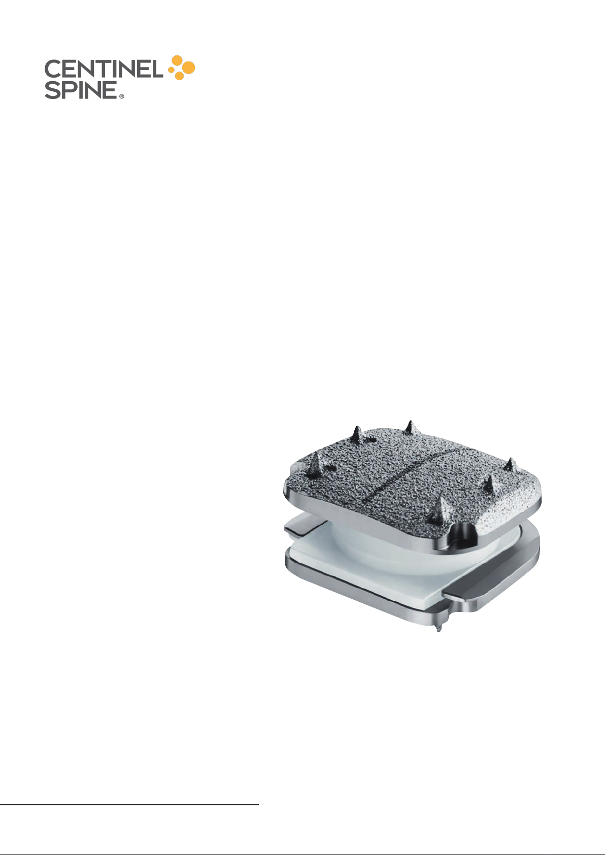
prodisc C Vivo implants are used to replace a cervical inter-
vertebral disc, to restore disc height and maintain
segmental motion.
Successful clinical outcomes depend on a number of critical
factors, including:
•Completion of a training program on the use of
prodisc C, prodisc C Nova or prodisc C Vivo
•Proper patient selection
•Adequate bone quality (investigation todetermine
bone quality isrecommended)
•Complete and meticulous discectomy, decompression,
and remobilization of the disc space
•Optimal implant sizing and placement
•Postoperative treatment
Indications
Symptomatic cervical disc disease (SCDD), which is defined
as neck or arm (radicular) pain and/or a functional/neuro-
logical deficit with at least one of the following conditions
confirmed by imaging (CT, MRI, or x-rays):
•herniated nucleus pulposus
•spondylosis (defined by the presence of osteophytes)
•loss of disc height
Specific contraindications
•Fractures, infections, tumors
•Spinal stenosis by hypertrophic spondylarthrosis
•Severe facet joint degeneration
•Segmental instability
•Ossification of posterior longitudinal ligament (OPLL)
General contraindications
•Osteoporosis, osteochondrosis, and severe osteopenia
•Acute or chronic systemic, spinal, or localized
infections
•Systemic and metabolic diseases
•Any medical and surgical conditions precluding
the benefits of spinal surgery
•Foreign body sensitivity to the implant materials
•Pregnancy
•Severe obesity (Body Mass Index above 40)
Patient exclusion recommendations
Patient selection is one of the most important factors
contributing to the outcome of the total disc replace-
ment procedure. The following may affect clinical out-
comes:
•A condition of senility or mental illness, alcoholism
or smoking
•Dependency on pharmaceutical drugs or drug abuse
•The patient’s occupation or activity level
•Compromised vertebral bodies at affected level due
to current or past trauma (fractures)
•Substantial loss of disc height, where applied segmen-
tal distraction may lead to damage of the great vessels
•Involved vertebral endplate dimensionally smaller than
the minimum implant footprint size in both the medial-
lateral and the anteriorposterior directions
•Severe abnormality of the endplate (e.g. large Schmorl
nodes)

prodisc C Vivo Surgical Technique Centinel Spine 5
SURGICAL TECHNIQUE
1
Prerequisites and patient positioning
Insertion of a prodisc C Vivo is dependent on the use of
anterior-posterior (AP) and lateral fluoroscopy throughout
the procedure. Patient positioning should allow for circum-
ferential use of the C-arm at the operative level.
Position the patient in a supine, neutral position on a radio-
lucent operating table. Ensure that the neck of the patient is
in a sagittally neutral position and supported by a cushion.
When treating C6–C7 make sure that the shoulders do not
limit the x-ray monitoring. In any case both vertebrae should
be completely visible.
2
Access
Use a standard anterior approach to the cervical spine. Mark
the level of the surgery and expose the intervertebral disc
segment and adjacent vertebrae.
Determine the median line using image intensifier control
and make a permanent midline mark on the superior and
inferior vertebral bodies, e.g. using an osteotome or electro
cauterization.

6 Centinel Spine prodisc C Vivo Surgical Technique
Surgical Technique
3
Fix retainer screw system
Instruments
03.820.100 Punch
03.820.101 Screwdriver
03.820.111 Vertebral Body Retainer
03.820.102– Retainer Screws
03.820.109
03.820.110 Locking Nut
Perforate the anterior cortex of the superior and inferior
vertebra in the lateral midline and vertical center with the
punch.
Insert retainer screws into the perforations and place them
close to the posterior cortical wall. Their trajectory should
be parallel to the endplates of the treated disc. Begin with
the smaller diameter screws (3.5 mm) of the longest possible
length. Use a larger diameter screw (4.5 mm) when extra
bone purchase is needed or a smaller screw diameter has
been used unsuccessfully (“rescue” screw).
Warning:
•Insert screws under image intensier control for
optimal trajectory and depth control.
•Do not perforate the posterior cortex with the tip
of the screw.
Slide the vertebral body retainer over the screws and lock it
in place with the locking nuts. This assembly secures parallel-
ism of the retainer screws and the vertebral endplates of the
operated level.
Avoid using the retainer to distract the segment. For proper
distraction refer to Step 4 on page 7.

prodisc C Vivo Surgical Technique Centinel Spine 7
4
Mobilize and distract the segment
Instrument
03.820.112 Vertebral Distractor
Start the discectomy using standard instruments.
Remove as much disc material as possible to allow the verte-
bral distractor tips to be placed as posteriorly as possible into
the intervertebral space. Mild predistraction with the retainer
can be applied to support disc removal.

8 Centinel Spine prodisc C Vivo Surgical Technique
Under fluoroscopic control, insert the tip of the vertebral
distractor to the posterior margin of the vertebral bodies.
Distract the intervertebral space with the vertebral distractor
to restore the height and to gain access to the posterior
intervertebral space. Readjust the retainer to the distracted
height of the intervertebral space. This step should be re-
peated until maximum distraction has been achieved. Then
release and withdraw the vertebral distractor.
Continue the discectomy and remove the cartilageous
endplate carefully. All soft tissue must be removed from the
endplates. Care should be taken to avoid damage of the
endplates.
Continue with the canal and foraminal decompression.
Precaution:
•Avoid using the vertebral body retainer as a dis-
tractor. Excess force on the vertebral body retainer
can lead to bending and/or pull-out of the screws
from the bone.
•Expose the posterior longitudinal ligament to
remobilize the segment. If required for decompres-
sion, the PLL may be resected.
Warning:
•Avoid overdistraction with the vertebral distractor
as this can lead to nerve root tension or improper
implant selection.
•Avoid excessive endplate damage or removal. This
increases the risk of implant subsidence.
•The uncinate process should be preserved. If re-
quired for adequate decompression, the posterior
third of the uncinatus process may be removed.
•Ensure the cartilageous tissue is removed from the
endplates. Cartilageous tissue may hinder osseo-
integration of the implant and reduce the xation
strength.
Surgical Technique

prodisc C Vivo Surgical Technique Centinel Spine 9
5
Define the implant size
Instruments
03.670.925– Trial Implants
03.670.977
03.670.204 Holder for Trial Implants
03.820.113 Mallet
After completing discectomy and decompression, use the
trial implants to determine the appropriate disc height and
size of footprint.
The goal is to select a prosthesis with the best possible
anatomical fit, using the largest footprint and the
smallest height needed to restore the natural disc.
Prosthesis center of rotation (COR) should be positioned at
the midline of the vertebral body or slightly posterior. The
implant should cover the majority of the vertebral body end-
plate. Implants with undersized footprints lead to increased
risk of implant subsidence and heterotopic ossification.
Insert the inner shaft of the holder for trial implants into the
corresponding sleeve and push it until it snaps into place.
Select the appropriate trial implant and make sure that its
protrusion is captured in the stop of the shaft before assem-
bling. Ensure that the shaft is fully screwed in before use.
Align the trial implant with the midline and advance it under
image intensifier control into the disc space by tapping it
cautiously.

10 Centinel Spine prodisc C Vivo Surgical Technique
In the lateral fluoroscopy view the optimal position of the
trial implant is given by the best possible anatomical fit. If the
stop does not allow the trial implant to go deep enough, the
stop can be adjusted by turning the trial shaft counter clock-
wise (1 rev = 0.5 mm), enabling the trial implant to be ad-
vanced slightly deeper. At the same time the trial implant
should be kept centered on the midline.
Now release the distraction to determine if the trial implant
height is appropriate for the patient. Its height should be the
smallest height to match normal adjacent discs. When the
correct size for the implant is determined, the trial implant is
removed (apply slight distraction with the vertebral retainer
if necessary).
Precaution:
•Selecting an implant that is too tall can limit the
segmental range of motion.
•Avoid kyphotic position of the corresponding
segment.
Note:
•Do not unscrew stop more than 4mm or contact
to trial implant may be lost. Use next size trial
implant instead.
Surgical Technique

prodisc C Vivo Surgical Technique Centinel Spine 11
6
Insert implant
Instruments
03.670.201– Implant Holder
03.670.203
03.670.213 Shaft for Implant Holder
03.670.212 Stop for Implant Holder (optional)
03.670.305– Spacer Clamp, sizes M/MD,
03.670.307 heights 5–7 mm
03.670.315– Spacer Clamp, sizes L/LD,
03.670.317 heights 5–7 mm
03.670.325– Spacer Clamp, sizes XL/XLD,
03.670.327 heights 5–7 mm
03.820.113 Mallet
03.820.101 Screwdriver
03.670.207 Positioner
Preparation
Assemble the shaft for the implant holder. Open the packag-
ing of the implant and follow these steps:
•Choose spacer clamp size M/MD, L/LD or XL/XLD
corresponding to the implant.
•Attach the appropriate spacer clamp to the prosthesis
until the arms snap into the holding features in the
implant.
•Attach the corresponding implant holder (M/MD, L/LD
or XL/XLD) to the spacer clamp, making sure that
the lateral projections of the spacer clamp are captured
in the arms of the implant holder.
•Tighten the implant holder to the spacer clamp turning
the head of the inner shaft clockwise.
•Pull the implant en-bloc out of the packaging tray.
Optionally, the stop can be attached to the implant holder.
Note: The prodisc C Vivo implants are not designed
to be used with bone cement.

12 Centinel Spine prodisc C Vivo Surgical Technique
Insertion
Apply distraction as necessary, to facilitate the insertion of
the implant.
Ensure that the black midline on the superior endplate faces
cranially and align it with the midline marking of the verte-
bral body.
Under lateral fluoroscopic control, advance the implant into
its final position providing the best possible anatomical fit
with the vertebral bodies. The center of rotation (COR) of the
prosthesis should be positioned at the midline of the verte-
bral body or slightly posterior. Avoid excessive cranial, caudal
or lateral corrections during insertion and ensure that the
implant doesn’t exceed the posterior margin of the vertebral
body.
The spacer clamp includes two grooves that visualize the
anterior margin of the implant under lateral fluoroscopy.
If the correct position of the implant is confirmed using im-
age intensifier, release the retainer and apply slight compres-
sion with the retainer. Slight compression from the retainer
will help the spikes on the implant to penetrate into the ver-
tebral bodies.
Surgical Technique
Without Stop With Stop

prodisc C Vivo Surgical Technique Centinel Spine 13
Release
To release the connection between spacer clamp and im-
plant, follow the two steps below:
1. Rotate the shaft of the implant holder two full turns
in the counterclockwise direction.
2. Move the implant holder sideward and pull it back
until the spacer clamp disconnects from the implant.
Step by step remove the locking nuts, the vertebral body
retainer and the retainer screws.
Precaution: Heterotopic ossication (HO) is a possi-
ble cause for fusion of the treated segment. Copious
saline lavage is recommended to remove osteogenic
stimuli (blood/bone marrow). HO might be reduced
when bone wax is used to close cavities in the bone
(screw holes) and open bone surfaces after removal
of anterior osteophytes.¹
¹ See Barbagallo 2014

14 Centinel Spine prodisc C Vivo Surgical Technique
MULTI-LEVEL CASES
The most symptomatic level should be operated first.
Multi-level prodisc C Vivo surgeries should be performed
sequentially level by level.
If no symptomatic difference between the levels can be
identified, start operating the most collapsed or caudal one.
The retainer screws should be placed centrally in the
vertebrae according to the surgical technique for single
levels.
Insert the screws under image intensifier control.
Repeated image intensifier control in AP direction will be
necessary to ensure proper alignment of the disc prostheses.

prodisc C Vivo Surgical Technique Centinel Spine 15
REMOVAL PROCEDURE
If a prodisc C Vivo implant must be removed,
the following technique is recommended.
1
Preparation
Instruments
03.670.201– Implant Holder
03.670.203
03.670.213 Shaft for Implant Holder
03.670.400 Remover Clamp size M/MD
03.670.410 Remover Clamp size L/LD
03.670.420 Remover Clamp size XL/XLD
Start the procedure by distracting the prosthesis index
level by using the vertebral distractor and the retainer
system. See page 6 for details on how to use the re-
tainer system.
Attach the appropriate remover clamp to the corre-
sponding implant holder with minimal thread engage-
ment without tightening the head of the inner shaft of
the implant holder.
Note: If the thread of the shaft is fully engaged and
tightened, the remover clamp cannot be attached to
the implant in the next step.
Attach the remover clamp assembly to the inferior end-
plate of the implant and securely attach it by turning the
head of the implant holder shaft in clockwise direction.
Note: The surface edged with “inside” must be
oriented towards the center of the disc space with
respect to the implant endplate being removed.

16 Centinel Spine prodisc C Vivo Surgical Technique
2
Implant Removal
Instruments
03.670.201– Implant Holder
03.670.203
03.670.213 Shaft for Implant Holder
03.670.400 Remover Clamp size M/MD
03.670.410 Remover Clamp size L/LD
03.670.420 Remover Clamp size XL/XLD
03.820.113 Mallet
03.820.282 Slide Hammer
Remove the inferior endplate of the implant by cautiously
pulling the implant holder. Alternatively, the slotted mallet or
slide hammer can be used to aid implant removal.
The superior endplate of the implant can be removed using
the remover clamps or alternatively suitable forceps.
Removal Procedure

14.5–19.2 mm 16.5–22.5 mm 15/17/19 mm
4.2–7.5 mm 5/6/7 mm
12/14/16/18 mm
prodisc C Vivo Surgical Technique Centinel Spine 17
IMPLANTS
Dimensions
Six different footprints are available
for optimal coverage of the vertebral
endplate: M, MD, L, LD, XL, XLD.
Three different heights (5, 6, and
7 mm) allow adjustment to the indi-
vidual dimensions of the patient’s
disc.
Panjabi 1991
Yoganandan et al. 2001

18 Centinel Spine prodisc C Vivo Surgical Technique
Implants
The prodisc C Vivo implant consists
of two titanium endplates. The superior
endplate has a convex shape, while the
inferior plate is flat. There are six spikes
on both plates.
prodisc C Vivo has always been based
on the ball and socket principle with
a “poly-on-metal” pairing. The poly-
ethylene inlay (ball) is securely locked in
the lower endplate while the upper
endplate embraces the calotte (socket)
made of CoCrMo alloy.
prodisc C Vivo, uncemented
Implant M
Width 15 mm
Depth 12 mm
Art. No. Height
04.670.925S 5 mm
04.670.926S 6 mm
04.670.927S 7 mm
Implant LD
Width 17 mm
Depth 16 mm
Art. No. Height
04.670.955S 5 mm
04.670.956S 6 mm
04.670.957S 7 mm
Implant MD
Width 15 mm
Depth 14 mm
Art. No. Height
04.670.935S 5 mm
04.670.936S 6 mm
04.670.937S 7 mm
Implant XL
Width 19 mm
Depth 16 mm
Art. No. Height
04.670.965S 5 mm
04.670.966S 6 mm
04.670.967S 7 mm
Implant L
Width 17 mm
Depth 14 mm
Art. No. Height
04.670.945S 5 mm
04.670.946S 6 mm
04.670.947S 7 mm
Implant XLD
Width 19 mm
Depth 18 mm
Art. No. Height
04.670.975S 5 mm
04.670.976S 6 mm
04.670.977S 7 mm
Table of contents