CentoLight Scenic C1012 User manual

Carefully read this manual and properly take care of it
Leggete questo manuale e conservatelo per future consultazioni
User Manual
Manuale Utente
12x10W RGBW 4in1 LED PAR with 25° beam for indoor use
PAR per uso interno con 12 LED da 10W RGBW 4in1 e apertura del fascio a 25°
ENG
ITA
Scenic C1012Scenic C1012

22
Dear customer,
First of all thanks for purchasing a CENTOLIGHT® product. Our mission is to satisfy
all possible needs of light designers and professionals of entertainment lighting, by
offering a wide range of products based on the latest technologies.
We hope you will be satisfied with this fixture and, if you want to collaborate, we
are looking for a feedback from you about product operation and possible im-
provements to be introduced in the next future. Go to our website www.centolight.
com and send an e-mail with your opinion; this will help us to build equipment ever
closer to professional’s real requirements.
The CENTOLIGHT Team
Gentile Cliente,
Grazie per aver scelto un prodotto CENTOLIGHT®. La nostra missione è quella di
soddisfare ogni possibile richiesta da parte di light designers e professionisti dell’il-
luminotecnica per l’intrattenimento, offrendo una vasta gamma di apparecchiature
basate su tecnologie di ultima generazione.
Speriamo di aver soddisfatto le vostre aspettative e, se voleste collaborare, sarem-
mo lieti di ricevere un vostro feedback sulla qualità del prodotto al fine di migliorare
costantemente la nostra produzione. Visitate il nostro sito www.centolight.com ed
inviateci una mail con la vostra opinione; questo ci aiuterà a sviluppare nuovi pro-
dotti quanto più vicini alle vostre esigenze.
Il Team CENTOLIGHT

33
Eng
Table of ConTenTs
1 - Before you Begin 4
1.1. What is included- - - - - - - - - - - - - - - - - - - - - - - - - - - - - - - - - - - - - - - - - - - - - - - - - - 4
1.2. Unpacking Instructions - - - - - - - - - - - - - - - - - - - - - - - - - - - - - - - - - - - - - - - - - - - - - 4
1.3. Accessories - - - - - - - - - - - - - - - - - - - - - - - - - - - - - - - - - - - - - - - - - - - - - - - - - - - - - 4
1.4. Disclaimer - - - - - - - - - - - - - - - - - - - - - - - - - - - - - - - - - - - - - - - - - - - - - - - - - - - - - - 5
2 - Safety Instructions 5
2.1. Symbols Meaning - - - - - - - - - - - - - - - - - - - - - - - - - - - - - - - - - - - - - - - - - - - - - - - - - 5
3 - Mounting and Rigging 6
3.1. Rigging - - - - - - - - - - - - - - - - - - - - - - - - - - - - - - - - - - - - - - - - - - - - - - - - - - - - - - - - 6
3.2. Water / Moisture - - - - - - - - - - - - - - - - - - - - - - - - - - - - - - - - - - - - - - - - - - - - - - - - - 6
3.3. Heat - - - - - - - - - - - - - - - - - - - - - - - - - - - - - - - - - - - - - - - - - - - - - - - - - - - - - - - - - - 7
3.4. Servicing - - - - - - - - - - - - - - - - - - - - - - - - - - - - - - - - - - - - - - - - - - - - - - - - - - - - - - - 7
4 - Introduction 7
4.1. Features - - - - - - - - - - - - - - - - - - - - - - - - - - - - - - - - - - - - - - - - - - - - - - - - - - - - - - - 7
4.2. Product Dimensions and Overview - - - - - - - - - - - - - - - - - - - - - - - - - - - - - - - - - - - - - 8
5 - Product Setup 9
5.1. Rear Panel Description- - - - - - - - - - - - - - - - - - - - - - - - - - - - - - - - - - - - - - - - - - - - - - 9
5.2. About Power Connection - - - - - - - - - - - - - - - - - - - - - - - - - - - - - - - - - - - - - - - - - - - 10
5.3. About Dmx Connection - - - - - - - - - - - - - - - - - - - - - - - - - - - - - - - - - - - - - - - - - - - - 10
5.4. DMX Terminator - - - - - - - - - - - - - - - - - - - - - - - - - - - - - - - - - - - - - - - - - - - - - - - - - 11
5.5. 3-Pin vs 5-Pin DMX cables - - - - - - - - - - - - - - - - - - - - - - - - - - - - - - - - - - - - - - - - - - 11
6 - Menu Operation 12
6.1. Set DMX Address - - - - - - - - - - - - - - - - - - - - - - - - - - - - - - - - - - - - - - - - - - - - - - - - 13
6.2. DMX Channel Assignments and Values - - - - - - - - - - - - - - - - - - - - - - - - - - - - - - - - - 13
6.3. Fan Noise & LED Temperature Control - - - - - - - - - - - - - - - - - - - - - - - - - - - - - - - - - - 14
6.4. Master/Slave Mode - - - - - - - - - - - - - - - - - - - - - - - - - - - - - - - - - - - - - - - - - - - - - - 15
7 - Troubleshooting 15
8 - Specication 16
9 - Warranty And Service 17
10 - Warning 18

44
SCENIC C1012 User Manual
Eng
1 - before you begin
Thank you for purchasing SCENIC C1012. Enjoy your new equipment and make sure
to read this manual carefully before operation! This user manual is made to provide
both an overview of controls, as well as information on how to use them.
1.1. What is included
Package include:
y1x CENTOLIGHT SCENIC C1012 PAR light
y1x 1m (40in ca.) Powercon to Europlug power cable
y1X 2m (79in ca.) DMX Cable 3-pin XLR-M to 3-pin XLR-F
yThis User Manual
ATTENTION: Packaging bag is not a toy! Keep out of reach of children!!! Keep in
a safe place the original packaging material for future use.
1.2. Unpacking Instructions
Carefully unpack the product immediately and check the content to make sure all
the parts are in the package and are in good condition.
If the box or the contents (the product and included accessories) appear damaged
from shipping, or show signs of mishandling, notify the carrier or dealer/seller imme-
diately. In addition, keep the box and contents for inspection.
If the fixture must be returned to the manufacturer, it is important that it is returned
in the original manufacturer box and packing. Please do not take any action without
first contacting your dealer or getting in touch with our after-sales support service
(visit www.centolight.com for details).
1.3. Accessories
CENTOLIGHT can supply a wide range of quality accessories that you can use with
your SCENIC Series equipment, like Cables, Splitters, DMX controllers, Consumables,
and a wide range of other fixtures.
All products in our catalogue has been long tested with this device, so we recom-
mend you to use Genuine CENTOLIGHT Accessories and Parts.
Ask your CENTOLIGHT dealer or check out our website www.centolight.com for any
accessories you could need to ensure best performance of the product.

55
SCENIC C1012 User Manual
Eng
1.4. Disclaimer
The information and specifications contained in this User Manual are subject to
change without notice. CENTOLIGHT assumes no responsibility or liability for any
errors or omissions and reserves the right to revise or to create this manual at any
time.
Copyright© 2021 CENTOLIGHT. All rights reserved.
2 - safeTy insTruCTions
yRead these instructions
yKeep these instructions
yHeed all warning
yFollow all instructions
2.1. Symbols Meaning
The symbol is used to indicate that some hazardous live termi-
nals are involved within this apparatus, even under the normal
operating conditions, which may be sufficient to constitute the
risk of electric shock or death.
The symbol is used to describe important installation or config-
uration problems. Not following advice and information on how
to avoid such problems may lead to product malfunction.
This symbol indicates a protective grounding terminal.
WARNING: Describes precautions that should be observed to prevent the
danger of injury or death to the operator.
To protect the environment, please try to recycle packing materi-
al and exhausted consumables as much as possible.
This symbol indicates that the fixture is intended to indoor use
only. Keep the machine dry and do not expose to rain and mois-
ture.
Don’t throw this product away just as general trash, please deal
with the product follow the abandon electronic product regula-
tion in your country.

66
SCENIC C1012 User Manual
Eng
3 - MounTing and rigging
Pay attention to safety! Please respectively consider the EN 60598-2-17 and the
national standard during the installation. Only authorized technicians can carry
out the installation.
3.1. Rigging
yThe installation of the fixture has to be built and constructed in a way that it
can hold 10 times the weight for 1 hour without any harming demolition. The
installation must always be secured with a secondary safety attachment, e.g. an
appropriate catch net. This secondary safety attachment must be constructed in
a way that no part of the installation can fall down if the main attachment fails.
yWhen rigging, de-rigging or servicing the fixture staying in the area below the
installation place, on bridges, under high working places and other endangered
areas is forbidden. The operator has to make sure that the safety measure and
the machine’s technical installation is approved by an expert before taking into
operation for the first time and after changes before taking into operation an-
ther time. He has also to make sure that an expert approves safety measure and
the machine’s technical installation once a years.
IMPORTANT: Overhead rigging requires extensive experience, including (but not
limited to) calculating working load limits, installation material being used, and
periodic safety inspection of all installation material and the projector. If you
lack these qualications, do not attempt the installation yourself, but instead
use a professional structural rigger. Improper installation can result in bodily
injury or property loss.
yIf the fixture shall be lowered from the ceiling or high joists, professional trussing
systems have to be used. The fixture must never be fixed swinging freely in the
room.
CAUTION: Use appropriate clamps to rig the xture on the truss. Make sure that
the device is xed properly! Ensure that the structure (truss) to which you are
attaching the xtures is secure.
3.2. Water / Moisture
yThe product is for indoor use. In order to prevent risk of fire or electric shock, do
not expose to rain or moisture

77
SCENIC C1012 User Manual
Eng
yThe unit can not be used near water; for example near a bathtub, a kitchen sink,
a swimming pool, etc.
3.3. Heat
yDo not use in a confined space. Always install the product in a location with
adequate ventilation, at least 20in (50 cm) from adjacent surfaces. Be sure that
no ventilation slots on the product’s housing are blocked.
yThe apparatus should be located away from heat sources such as radiators,
stoves or other appliances that produce heat.
Don not use it when maximum ambient temperature is higher than 50°C. Work
temperature ranges from -20°C to 50°C (-4°F to 122°F).
3.4.Servicing
yDo not implement any servicing other than those means described in the man-
ual. Refer all servicing to qualified service personnel only. The internal compo-
nents of the equipment must be purchased from the manufacturer. Only use
accessories/attachments or parts recommended by the manufacturer.
4 - inTroduCTion
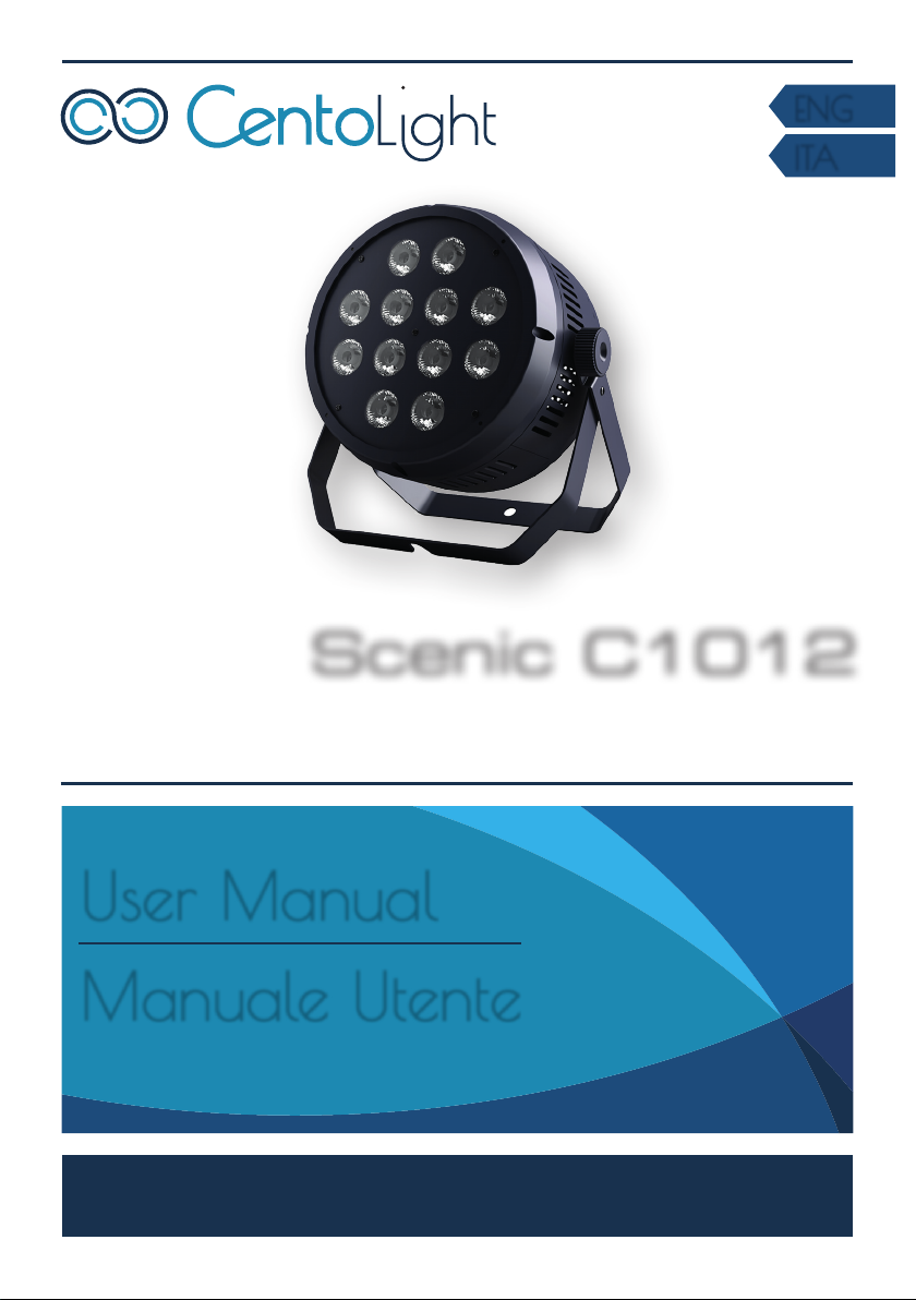
SCENIC C1012 is a compact and lightweight LED Par designed for live events, club
installations and all those indoor applications where colored lights with narrow
beam (25°) are required. The light source features 12x10W RGBW 4in1 LEDs, de-
signed to create bright and intense colors.
Its main strengths are reliability and flexibility. The first is based on quality and
selection of LED chips, the quality of optical lenses and the use of digital processor
technology for LED chip temperature and fan speed control in order to preserve LED
life and color brilliance. The second point, flexibility, means that users can choose to
turn off the fan by renouncing part of luminance and make the fixture totally silent.
This could be very useful to rental companies and professionals in all those “on the
fly” situations, where total silence is needed (houses of worship, theaters, confer-
ence halls, etc.) and do not have silent multicolor fixtures enough or simply because
the installation requires more fixtures than those available.
SCENIC C1012 is color at hand, without hassles in any venue.
4.1. Features
yHigh brightness / long lifespan LED chips with high-quality lens
yRGBW 4in1 color mixing

88
SCENIC C1012 User Manual
Eng
yFlicker-free LED emission for broadcast applications
y6/9CH DMX-512 control with RDM
y25° beam angle with advanced dimmer system and strobo effects
yIntelligent fan speed and control with low-noise fan
yLightweight aluminum housing with all-directional ventilation system
4.2.Product Dimensions and Overview
253mm (9.96”)
282mm (11.10”)
295mm (11.61”)
Ø228mm (8.98”)
282.2mm (11.11”) 282.2mm (11.11”)
295mm (11.61”)
158.5mm (6.24”)
138.5mm (5.45”)
228mm (8.98”)
228mm (8.98”)
138.5mm (5.45”)
Brackets
Adjustment
knob
Security
eye-bolt
Power & DMX
Connections
Display &
Control Panel

99
SCENIC C1012 User Manual
Eng
5 - ProduCT seTuP
5.1. Rear Panel Description
MENU UP DOWN ENTER
1
2
The operation panel includes the LED display and control button operation area.
1) 4 Digit LED Display
It shows the operating mode and other system information.
2) Control Buttons
MENU Button - Short-press it to switch the setting pages.
UP Button - It scrolls up individual items in the selection menu and sub-menus for
system settings (DMX address, Operation Mode, etc.), and increases values/settings
of parameters.
DOWN Button - It scrolls down individual items in the selection menu and sub-
menus for system settings (DMX address, Operation Mode, etc.), and increases
values/settings of parameters.
ENTER Button - Press ENTER to access menu levels and confirm parameter value
changes.
DMX POWER
IN OUTIN OUT
34
3) Power Input/Output Sockets
Plug the power-cord included with SCENIC C1012 into an AC socket properly config-
ured for this fixture. Please read “5.2. About Power Connection” on page 10 for
details. This fixture is also equipped with an output power connector to be used as
power mains source in case of cascade connection up to a maximum of 5 fix-
tures.

1010
SCENIC C1012 User Manual
Eng
1st Unit 5th Unit4th Unit3rd Unit2nd Unit
Power Input
100-240Vac - 50/60Hz
up to 10 units
4) DMX Input/Output Sockets
DMX Input is a 3-pin male XLR socket for connection to a DMX control device. DMX
output is a3-pin female socket for sending the DMX control signal to other units.
5.2. About Power Connection
yAlways make sure that the voltage of the outlet you are connecting the product
to is within the range stated in paragraph “8 - Specification” on page 16 or
rear panel of the product (AC110V-240V 50/60Hz).
yMake sure the power cord is not crimped or damaged. Never connect this prod-
uct to a dimmer pack or rheostat.
yNever disconnect the product from power cord by pulling or tugging on the cord.
yTo avoid electric shock, all fixtures must be connected to circuits with a suitable
ground and circuit breaker.
yWire correspondence is as follows:
Cable (EU) Pin International
Brown Live L
Blue Neutral N
Yellow/Green Earth
Earth must be connected! Always pay attention to safety! Before taking into
operation for the rst time, the installation has to be approved by an expert.
5.3. About Dmx Connection
When use a DMX controller, please make sure that there is no interference
sources (e.g. intercom, high frequency radio waves and radiation source).
DMX machines are designed to receive data through a serial Daisy Chain. A Daisy
Chain connection is where the DATA OUT of one fixture connects to the DATA IN of
the next fixture. The order in which the machines are connected is not important
and has no effect on how a controller communicates to each of them. Use an order

1111
SCENIC C1012 User Manual
Eng
that provides for the easiest and most direct cabling.
3-Pin XLR
Pin 1: GND
Pin 2: DMX -
Pin 3: DMX +
OUTPUTINPUT
DMX use of 3-Pin XLR Connectors
DMX Termonator
Unit 1 Unit 2 Last Unit
DMX 512
Connect machines using shielded 2-conductor twisted pair cable with 3-pin XLR
male to female connectors. The shield connection is pin 1, while pin 2 is Data Nega-
tive (S-), and pin 3 is Data positive (S+).
CAUTION: Wires must not come into contact with each other; otherwise the x-
tures will not work at all, or will not work properly.
5.4.DMX Terminator
120ohm, 1/4W
Resistor
DMX Terminator
DMX is a resilient communication protocol, however errors still
occasionally occur. In order to prevent electrical noise from dis-
turbing and corrupting the DMX control signals, a good habit is to
connect DMX output of last fixture in the chain to a DMX termina-
tor, especially over long signal cable runs.
The DMX terminator is simply an XLR connector with a 120
(ohm), 1/4 Watt resistor connected across Signal (-) and Signal (+),
respectively, pins 2 and 3, which is then plugged into the output
socket on last projector in the chain. The connections are illustrat-
ed below.
Complimentary signal cable can transmits signals to 20 unit xtures at most.
Signal amplier is a must to connect more xtures.
5.5. 3-Pin vs 5-Pin DMX cables
DMX connection protocols used by controllers and fixtures manufacturers are not
standardized around the world. However, two are the most common standards:
5-Pin XLR and 3-Pin XLR system. If you wish to connect this fixture to a 5-Pin XLR in-
put fixture, you need to use an adapter-cable or make it by yourself. Below you can
see the wiring correspondence between 3-Pin and 5-Pin plug and socket standards

1212
SCENIC C1012 User Manual
Eng
5-Pins XLR (plug)
Pin 1: GND (Screen)
Pin 2: Signal (-)
Pin 3: Signal (+)
Pin 4: N/C
Pin 5: N/C
3-Pins XLR (socket)
Pin 1: GND (Screen)
Pin 2: Signal (-)
Pin 3: Signal (+)
5-Pins XLR (socket)
Pin 1: GND (Screen)
Pin 2: Signal (-)
Pin 3: Signal (+)
Pin 4: N/C
Pin 5: N/C
3-Pins XLR (plug)
Pin 1: GND (Screen)
Pin 2: Signal (-)
Pin 3: Signal (+)
6 - Menu oPeraTion
By pressing MENU button, the display will cycle through 12 different menus. Press
ENTER button to enter the corresponding menu, press UP or DOWN to modify cur-
rent parameter value. Then, press ENTER button again to save current value.
No. Menu Function
1 d--- DMX512 address code setting: 001-512. When there is an incoming DMX signal, the
lower right corner indicator lights up
2 r--- Red brightness adjustment: 0-255
3 G--- Green brightness adjustment: 0-255
4 b--- Blue brightness adjustment: 0-255
5 n--- White brightness adjustment: 0-255
6 F---
Stroboscopic/speed adjustment:
0 = N/C
1-84 = lightning strobo
85-169 = random strobo
170-255 = standard stroboscopic
7Pr--
(Internal
Preset)
PR01 red
PR02 green
PR03 blue
PR04 white
PR05 red + green
PR06 red + blue
PR07 green + blue
PR08 red + green + blue + white
PR09 hopping
PR10 gradient
PR11 strobe
PR12 combined effect
8 SP-- Built-in program speed setting: SP01-16
9 AU-- Auto/Audi: Auto/Sound control
10 FAN-
(*)
FAN0: Fan works only when LED temperature is above 40°C
FAN1: Silent mode
FAN2: Fan always working
11 dp-- dp0/1: 30s instant blackout and light on
12 CH-- CH9/CH6 Model selection
(*) Read “6.3. Fan Noise & LED Temperature Control” on page 14 for further
details.

1313
SCENIC C1012 User Manual
Eng
6.1. Set DMX Address
When selecting a starting DMX address, always consider the number of DMX chan-
nels. If you choose a starting address that is too high, you could restrict the access
to some of the product’s channels. SCENIC C1012 uses 6 DMX channels or 9 DMX
channel (according to the DMX mode chosen), which defines the highest configu-
rable address to 505 or 496 to have all channels controllable.
Set the SCENIC C1012 starting address in the 001 - 505 DMX range to enable control
of up to 85 products in the 6-channel control mode. Set the SCENIC C1012 starting
address in the 001 - 496 DMX range to enable control of up to 56 products in the
9-channel control mode.
To choose between 6 or 9 channel operation, press MENU till you reach “CH--”
page and press ENTER; you then see current CH9 or CH6 current mode. Press UP or
DOWN to select desired value. Then press ENTER to confirm, and press MENU to
return to menu main page.
To change DMX address, press MENU till you reach “d---” page and press ENTER;
you then see current DMX channel. Press UP or DOWN to select desired value ac-
cording to previous instructions. Then press ENTER to confirm, and press MENU to
return to menu main page.
6.2. DMX Channel Assignments and Values
When use DMX control , the system takes 6 or 9 channels (depending on selected
DMX mode. Below you can see the channel assignments for both modes.
1) 9-ch DMX512 Channel Chart
CHANNEL FUNCTION DESCRIPTION
Channel 1 Total Dimming 0-255: Total dimming linear dimming , from Dark to Bright.
Channel 2 Red 0-255: Red linear dimming, from Dark to Bright.
Channel 3 Green 0-255: Green linear dimming, from Dark to Bright.
Channel 4 Blue 0-255: Blue linear dimming, from Dark to Bright.
Channel 5 White 0-255: White linear dimming, from Dark to Bright.
Channel 6 Strobe
0: N/C
1-84: Conventional Strobo
85-169: Random Strobo
170-255: Lightning Strobo
Channel 7 Color Preset
0: N/C
1-30 Red
31-61 Green
62-92 Blue
93-123 White
124-154 Red+Green
155-185 Red+Blue
186-216 Green + Blue
217-255 Full Light

1414
SCENIC C1012 User Manual
Eng
Channel 8 Static Mixing + Auto
0-20: N/C
21-38 Red
39-57 Green
58-76 Blue
77-95 White
96-114 Red+Green
115-133 Red+Blue
134-152 Green+Blue
153-171 Full Bright
172-190 Gradient
191-209 Jump
210-228 Strobe
229-255 Complete Effect
Channel 9 Auto Speed 0-255 : Auto Speed Adjustment, from Fast to Slow
2) 6-ch DMX512 Channel Chart
CHANNEL FUNCTION DESCRIPTION
Channel 1 Total dimming 0-255 : Total Linear Dimming , from Dark to Bright.
Channel 2 Red 0-255 : Red Linear Dimming, from Dark to Bright.
Channel 3 green 0-255 : Green Linear Dimming, from Dark to Bright.
Channel 4 blue 0-255 : Blue Linear Dimming, from Dark to Bright.
Channel 5 white 0-255 : White Linear Dimming, from Dark to Bright.
Channel 6 Strobe 0: N/C
1-84: Conventional Strobo 85-169: Random Strobo
170-255: Lightning Strobo
6.3. Fan Noise & LED Temperature Control
SCENIC C1012 is equipped with a digital processor that controls fan speed and LED
temperature. Users can choose among 3 operative modes from FAN0 to FAN2 as
explained in “6 - Menu Operation” on page 12.
Users can select the desired mode by pressing MENU button until they reach the
“FAN-” page. Press ENTER; you see the current value. Then press UP or DOWN to
choose from FAN0 to FAN2. Press ENTER to confirm and MENU to go back to the
selection of menu pages.
FAN0 keeps the fan off when LED temperature is below 40°C (104°F). It comes into
operation form 41°C (105°F ca.), and the DSP increases fan speed according to LED
board temperature. Heat protection limit is fixed at 90°C; in normal conditions, this
limit is never exceeded, as fan would act to cool the chip. Maximum noise @ 1m
(max. fan speed) is 43dBA ca.
FAN1 (Silent Mode) always switches the fan off. Internal DSP controls the LED
temperature and adjusts its brightness to keep the chip always cooled. Brightness
reduction starts from 41°C (0% reduction) to 87°C (40% reduction ca.). Fan noise is
0dBA.
FAN2 preset keeps the fan always working, so the LED board temperature will al-
ways be kept cooled. Fan noise @ 1m is 43dBA ca.

1515
SCENIC C1012 User Manual
Eng
6.4.Master/Slave Mode
In case you need to control more SCENIC C1012 simultaneously (all fixtures operate
exactly the same way) without the use of a DMX controller, you can use the Master/
Slave function. There is no specific function to be activated on the display; simply
the master unit must be connected first, all the others in daisy-chain through the
DMX IN-OUT connections. All units (master and slaves) should be in DMX Channel
001 only, and have same Channel Mode (all 6CH or 9CH).
7 - TroubleshooTing
Problem Probable Cause(s) Remedy
No response from fixture
when power is applies No power to fixture Check power cables
Check mains plug
Fixture does not reset
correctly Electronic failure Contact service technician*
No light, LED cuts out
intermittently, or burns out
too quickly
LED missing or blown Disconnect fixture and replace
the LED
Fixture or LED is too hot Allow fixture to cool. If prob-
lem persists, contact service
technician*
Fixture resets but does
not respond correctly to
controller (DMX mode
operation)
Controller not connected Connect controller
Incorrect addressing of the
fixtures Check address setting on fixture
and controller
Bad data link connection Inspect cables and correct poor
connections and/or broken
cables.
Conflict between tracking
and vector control Eliminate scene cross-fade on
controller
Data link not terminated Insert termination plug in output
of last fixture**
Defective fixture on 2 devices
transmitting on link
Bypass fixtures one at a time
until normal operation is
regained: unplug both connec-
tors and connect them directly
together
* To contact CentoLight service, see “9 - Warranty And Service” on page 17 or visit www.centolight.
com
** For instruction on how to install a DMX terminator, see “5.4. DMX Terminator” on page 11.

1616
SCENIC C1012 User Manual
Eng
8 - sPeCifiCaTion
Light Source 12 x 10W LED
Color System RGBW 4in1
LED Control Flicker-free
Optical System 25° lens
Light Source Life-Cycle > 50.000 h
Dimmer 0-100% linear dimming with Sinusoidal Smooth Subdivision
Technology
DMX Control Mode DMX512 6CH/9CH with RDM
Operating Modes Master/Slave, Sound Active, Manual
Strobe 0-30Hz
Cooling System All-Direction Ventilating System with DSP control (fan is
stopped when LED board temperature is under 40°C; it runs
when it is over)
Fan Noise 0dB (temp under 40°C); 43.0 dBA @ 0.5m (temp. above 41°C);
46.1 dBA close to fixture
IP Rate IP20
Working Temperature Room Temperature between -20°C and 50°C (-4°F to 122°F)
Housing Aluminum with fine sand wear-resistant spray paint
Operating Voltage 110V-240V / 50-60Hz
Power Consumption 140W max.
Fixture Size (LxD) Min. Ø228 x 138.5 mm (Ø8.98 x 5.45 in); Max. - bracket includ-
ed - Ø282 x 253 mm (Ø11.10 x 9.96 in)
Fixture Weight 2,7 kg (5.95 lbs.)
Carton Size (LxHxD) 290 x 290 x 290 mm (11.42 x 11.42 x 11.42 in)
Carton Weight 3,75 kg (8.27 lbs.)
Note: Our products are subject to a process of continual further development. Therefore modifications to
the technical features remain subject to change without further notice.

1717
SCENIC C1012 User Manual
Eng
9 - WarranTy and serviCe
All CENTOLIGHT products feature a limited two-year warranty. This two-year
warranty starts from the date of purchase, as shown on your purchase receipt. The
following cases/components are not covered by this warranty:
yAny accessories supplied with the product
yImproper use
yFault due to wear and tear
yAny modification of the product effected by the user or a third party
CENTOLIGHT shall satisfy the warranty obligations by remedying any material or
manufacturing faults free of charge at CENTOLIGHT’s discretion either by repairing
or exchanging individual parts or the entire appliance. Any defective parts removed
from a product during the course of a warranty claim shall become the property of
CENTOLIGHT.
While under warranty, defective products may be returned to your local CENTOLI-
GHT dealer together with the original proof of purchase. To avoid any damages in
transit, please use the original packaging if available. Alternatively, you can send
the product to CENTOLIGHT SERVICE CENTER – Via Enzo Ferrari, 10 – 62017 Porto
Recanati - Italy. In order to send a product to service center, you need an RMA num-
ber. Shipping charges have to be covered by the owner of the product.
For further information please visit www.centolight.com

1818
SCENIC C1012 User Manual
Eng
10 - Warning
PLEASE READ CAREFULLY – EU and EEA (Norway, Iceland and Liechtenstein) only
This symbol indicates that this product is not to be disposed of with your household
waste, according to the WEEE Directive (2012/19/UE) and your national law.
This product should be handed over to a designated collection point, e.g., on an au-
thorized one-for-one basis when you buy a new similar product or to an authorized
collection site for recycling waste electrical and electronic equipment (WEEE).
Improper handling of this type of waste could have a possible negative impact on
the environment and human health due to potentially hazardous substances that
are generally associated with EEE. At the same time, your cooperation in the correct
disposal of this product will contribute to the effective usage of natural resources.
For more information about where you can drop off your waste equipment for recy-
cling, please contact your local city office, waste authority, approved WEEE scheme
or your household waste disposal service.

1919
Manuale Utente SCENIC C1012
Ita
soMMario
1 - Prima Di Iniziare 20
1.1. Cosa è Incluso - - - - - - - - - - - - - - - - - - - - - - - - - - - - - - - - - - - - - - - - - - - - - - - - - - 20
1.2. Istruzioni per il Disimballaggio - - - - - - - - - - - - - - - - - - - - - - - - - - - - - - - - - - - - - - - 20
1.3. Accessori- - - - - - - - - - - - - - - - - - - - - - - - - - - - - - - - - - - - - - - - - - - - - - - - - - - - - - 20
1.4. Limiti di Responsabilità - - - - - - - - - - - - - - - - - - - - - - - - - - - - - - - - - - - - - - - - - - - - 21
2 - Istruzioni di Sicurezza 21
2.1. Significato dei simboli - - - - - - - - - - - - - - - - - - - - - - - - - - - - - - - - - - - - - - - - - - - - - 21
3 - Montaggio e Appendimento 22
3.1. Installazione Sospesa - - - - - - - - - - - - - - - - - - - - - - - - - - - - - - - - - - - - - - - - - - - - - 22
3.2. Acqua / umidità - - - - - - - - - - - - - - - - - - - - - - - - - - - - - - - - - - - - - - - - - - - - - - - - - 22
3.3. Calore - - - - - - - - - - - - - - - - - - - - - - - - - - - - - - - - - - - - - - - - - - - - - - - - - - - - - - - - 23
3.4. Manutenzione - - - - - - - - - - - - - - - - - - - - - - - - - - - - - - - - - - - - - - - - - - - - - - - - - - 23
4 - Introduzione 23
4.1. Caratteristiche - - - - - - - - - - - - - - - - - - - - - - - - - - - - - - - - - - - - - - - - - - - - - - - - - - 23
4.2. Dimensioni e Panoramica del Prodotto- - - - - - - - - - - - - - - - - - - - - - - - - - - - - - - - - - 24
5 - Setup del prodotto 25
5.1. Descrizione del pannello posteriore- - - - - - - - - - - - - - - - - - - - - - - - - - - - - - - - - - - - 25
5.2. Connessioni di Rete- - - - - - - - - - - - - - - - - - - - - - - - - - - - - - - - - - - - - - - - - - - - - - - 26
5.3. Connessioni DMX - - - - - - - - - - - - - - - - - - - - - - - - - - - - - - - - - - - - - - - - - - - - - - - - 26
5.4. Terminatore DMX - - - - - - - - - - - - - - - - - - - - - - - - - - - - - - - - - - - - - - - - - - - - - - - - 27
5.5. Cavi DMX 3-Poli/5-Poli- - - - - - - - - - - - - - - - - - - - - - - - - - - - - - - - - - - - - - - - - - - - - 27
6 - Funzionamento dei Menu 28
6.1. Impostazione dell’indirizzo DMX.- - - - - - - - - - - - - - - - - - - - - - - - - - - - - - - - - - - - - - 29
6.2. Assegnazioni e valori dei canali DMX - - - - - - - - - - - - - - - - - - - - - - - - - - - - - - - - - - 29
6.3. Controllo della ventola e della temperatura del LED- - - - - - - - - - - - - - - - - - - - - - - - - 30
6.4. Modalità Master/Slave - - - - - - - - - - - - - - - - - - - - - - - - - - - - - - - - - - - - - - - - - - - - 31
7 - Risoluzione dei Problemi 31
8 - Speciche Tecniche 32
9 - Garanzia e Assistenza 33
10 - Avviso UE e SEE (Norvegia, Islanda, Liechtenstein) 34

2020
Manuale Utente SCENIC C1012
Ita
1 - PriMa diiniziare
Grazie per aver acquistato il faro SCENIC C1012. Prima di iniziare, assicuratevi di leg-
gere attentamente questo manuale! Esso utente è stato creato per fornire sia una
panoramica dei controlli, sia informazioni su come usarli.
1.1. Cosa è Incluso
La confezione include:
y1x proiettore CENTOLIGHT SCENIC C1012
y1X Cavo di Rete da 1m (40in c.) con connettore Powercon e Europlug (tedesca)
y1x Cavo da 2m (79in ca.) DMX XLR 3pin Maschio - XLR 3-pin Femmina
yQuesto Manuale d’uso
ATTENZIONE: La confezione non è un giocattolo! Tenere fuori dalla portata dei
bambini! Conservare in un luogo sicuro il materiale di imballaggio originale.
1.2. Istruzioni per il Disimballaggio
Tirare fuori dall’imballo il prodotto con attenzione e controllare il cartone per assi-
curarsi che tutte le parti siano nella confezione e siano in buone condizioni.
Se la confezione o il contenuto (il prodotto e gli accessori inclusi) risultano danneg-
giati dalla spedizione o mostrano segni di maltrattamento, avvisare immediata-
mente il vettore o il rivenditore. Inoltre, conservare la scatola e il contenuto per una
eventuale ispezione.
Se l’apparecchiatura dovesse essere restituita al produttore, è importante che
venga riportata o spedita nell’imballo originale del produttore. Si prega di non
intraprendere alcuna azione senza prima contattare il proprio rivenditore o aver
contattato il nostro servizio di assistenza post-vendita (visitare www.centolight.com
per i dettagli).
1.3. Accessori
CENTOLIGHT fornisce un’ampia gamma di accessori di qualità che è possibile utiliz-
zare con le apparecchiature della serie SCENIC, come cavi, splitter, controller DMX,
materiali di consumo e un’ampia gamma di altri fari.
Tutti i prodotti nel nostro catalogo sono stati testati a lungo con questo dispositivo,
quindi ti consigliamo di utilizzare accessori e ricambi originali CENTOLIGHT.
Chiedete al vostro rivenditore CENTOLIGHT o visitate il nostro sito web www.centoli-
ght.com per eventuali accessori di cui potreste aver bisogno per garantire le migliori
prestazioni al vostro prodotto.
Table of contents
Languages:
Other CentoLight Dj Equipment manuals

CentoLight
CentoLight LIGHTBLASTER 1200WP User manual

CentoLight
CentoLight ZEPHIRO SNOW 600 User manual

CentoLight
CentoLight Scenic W504 User manual

CentoLight
CentoLight Lightblaster 200 User manual

CentoLight
CentoLight Plot 120F User manual

CentoLight
CentoLight ZEPHIROSNOW 1250 User manual

CentoLight
CentoLight Square 100PZ User manual

CentoLight
CentoLight Zephiro Bubble 300 User manual

CentoLight
CentoLight Scenic C1018Z User manual