CENTURION SYSTEMS CLAWS User manual

CLAWS - DIRECT DRIVE
INSTALLATION MANUAL
TRAFFIC BARRIERS
Centurion Systems (Pty) Ltd
www.centsys.com

After-sales
multi-language
Technical Support
Monday to Friday
from 07h00 to 18h00
GMT+2
Saturdays
08h00 to 16h30 GMT +2
Manufactures to
international
quality standard
ISO 9001:2008
100%
testing of
products
In-house
R&D
development
team
Centurion Systems (Pty) Ltd reserves the right to make changes to the products described in this
manual without notice and without obligation to notify any persons of any such revisions or changes.
Additionally, Centurion Systems (Pty) Ltd makes no representations or warranties with respect to
this manual. No part of this document may be copied, stored in a retrieval system or transmitted in any
form or by any means electronic, mechanical, optical or photographic, without the express prior written
consent of Centurion Systems (Pty) Ltd.
1986 1990 1995 1999 Today
Sales and technical support
to Africa, Europe, Asia,
the Americas, Australia
and the Pacific
Company Profile

page 3 www.centsys.com
1. General Description
2. Product Specifications
2.1. Technical Specifications
2.2. Product Dimensions
2.2.1. Surface Mount
2.2.2. Flush Mount
Surface Mount Installations
3. Product Identification
4. Tools Required
5. Introduction
5.1. Installation Configurations
5.1.1. Orientation of Installation
5.1.2. Spike Impact Direction
6. RHS Surface Mount - Similar Direction of Travel
6.1. Configuring the Drive Linkage Assembly
6.2. Spike Module Assembly
6.3. Re-assembling the Ramp Plates and Linkage Cover
6.4. Integrating the SECTOR II with the CLAWS
6.5. Completing the Assembly
7. RHS Surface Mount - Opposing Direction of Travel
7.1. Configuring the Drive Linkage Assembly
7.2. Spike Module Assembly
7.3. Re-assembling the Ramp Plates and Linkage Cover
7.4. Integrating the SECTOR II with the CLAWS
7.5. Completing the Assembly
page 8
page 8
page 8
page 9
Page 9
Page 9
page 10
page 11
page 12
page 12
page 12
page 12
page 14
page 16
page 16
page 19
page 26
page 28
page 32
page 33
page 33
page 36
page 43
page 45
page 49
SAFETY
FIRST IMPORTANT SAFETY INSTRUCTIONS
Contents
page 6

page 4 www.centsys.com
8. LHS Surface Mount - Similar Direction of Travel
8.1. Configuring the Drive Linkage Assembly
8.2. Spike Module Assembly
8.3. Re-assembling the Ramp Plates and Linkage Cover
8.4. Integrating the SECTOR II with the CLAWS
8.5. Completing the Assembly
9. LHS Surface mount - Opposing Direction of Travel
9.1. Configuring the Drive Linkage Assembly
9.2. Spike Module Assembly
9.3. Re-assembling the Ramp Plates and Linkage Cover
9.4. Integrating the SECTOR II with the CLAWS
9.5. Completing the Assembly
Flush Mount Installations
10. Product Identification
11. Tools Required
12. Introduction
12.1. Installation Configurations
12.1.1. Orientation of Installation
12.1.2. Spike Impact Direction
13. RHS Flush Mount - Similar Direction of Travel
13.1. Configuring the Drive Linkage Assembly
13.2. Spike Module Assembly
13.3. Preparing the Trench and Drainage System
13.4. Re-assembling the Ramp Plates and Linkage Cover
13.5. Integrating the SECTOR II with the CLAWS
13.6 Completing the Assembly
page 51
page 51
page 54
page 61
page 63
page 67
page 69
page 69
page 72
page 79
page 81
page 85
page 87
page 88
page 89
page 90
page 90
page 90
page 91
page 93
page 93
page 96
page 103
page 105
page 106
page 110
CONTENTS

page 5 www.centsys.com
14. RHS Flush Mount - Opposing Direction of Travel
14.1. Configuring the Drive Linkage Assembly
14.2. Spike Module Assembly
14.3. Preparing the Trench and Drainage System
14.4. Re-assembling the Ramp Plates and Linkage Cover
14.5. Integrating the SECTOR II with the CLAWS
14.6 Completing the Assembly
15. LHS Flush Mount - Similar Direction of Travel
15.1. Configuring the Drive Linkage Assembly
15.2. Spike Module Assembly
15.3. Preparing the Trench and Drainage System
15.4. Re-assembling the Ramp Plates and Linkage Cover
15.5. Integrating the SECTOR II with the CLAWS
15.6 Completing the Assembly
16. LHS Flush Mount - Similar Direction of Travel
16.1. Configuring the Drive Linkage Assembly
16.2. Spike Module Assembly
16.3. Preparing the Trench and Drainage System
16.4. Re-assembling the Ramp Plates and Linkage Cover
16.5. Integrating the SECTOR II with the CLAWS
16.6 Completing the Assembly
17. Wiring Diagram
18. Installation Handover
Icons used in this manual
This icon indicates tips and other
information that could be useful
during the installation.
This icon denotes variations
and other aspects that should be
considered during installation.
This icon indicates warning,
caution or attention! Please
take special note of critical
aspects that MUST be adhered
to in order to prevent injury.
This icon indicates areas
where mechanical crushing
may occur
CONTENTS
page 111
page 111
page 114
page 121
page 123
page 124
page 128
page 129
page 129
page 132
page 139
page 141
page 142
page 146
page 147
page 147
page 150
page 157
page 159
page 160
page 164
page 165
page 166
CONTENTS

page 6 www.centsys.com
ATTENTION
To ensure the safety of people and possessions, it is important that you
read all the following instructions.
Incorrect installation or incorrect use of the product may cause
serious harm to people and / or property.
The installer, being either professional or DIY, is the last person
on the site who can ensure that the operator is safely installed, and that
the whole system can be operated safely.
IMPORTANT
SAFETY INSTRUCTIONS
Warnings for the installer
CAREFULLY READ AND FOLLOW ALL INSTRUCTIONS before beginning to install
the product.
• All installation, repair, and service work to this product must be done by a suitably
qualified person
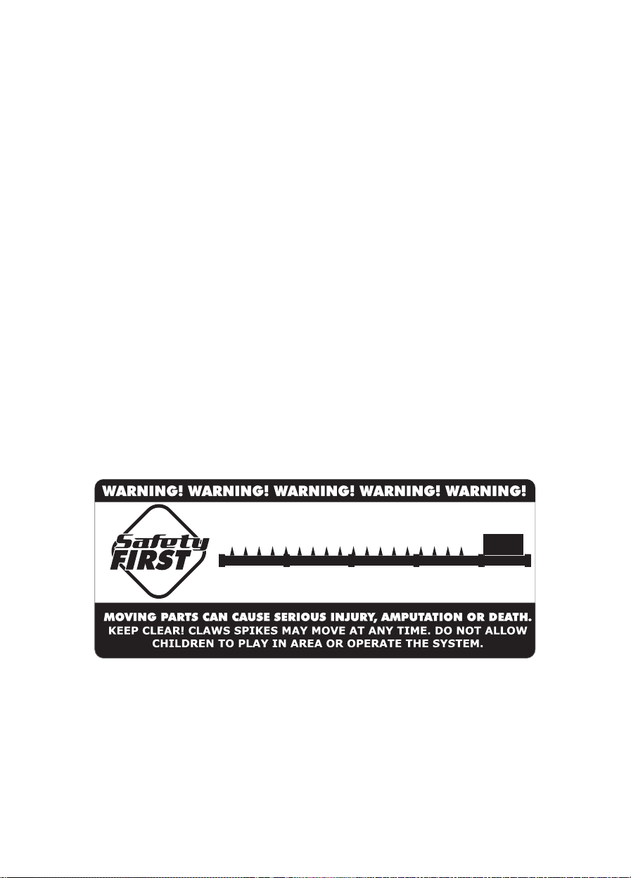
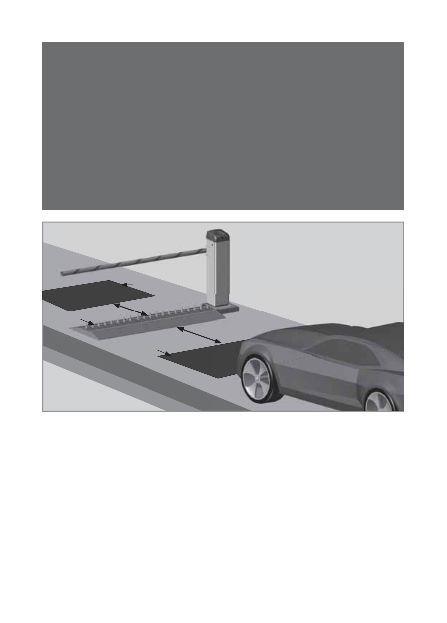
• Do not activate the CLAWS unless you can see them and can determine that the
CLAWS are clear of people, pets, vehicles or any obstructions.
• Nothing must be placed on or near the trench covers at any time.
• No one must be near the trench covers at any time. Always keep people and objects
away from the spikes’ area of travel
• Children should be supervised to ensure that they do not play with or around the
spikes and trench cover
• This device is not intended for use by persons (including children) with reduced
physical, sensory or mental capabilities, or lack of experience and knowledge, unless
they have been given supervision or instruction concerning use of the appliance by a
person responsible for their safety
• Secure all easily-accessed CLAW controls in order to prevent unauthorised use
• Do not in any way modify the components of the automated system
• Do not install the equipment in an explosive atmosphere. The presence of flammable
gas or fumes is a serious danger to safety
• Before attempting any work on the system, cut electrical power and disconnect the
batteries
• The mains power supply of the automated system must be fitted with a double pole
switch with contact opening distance of 3mm or greater. Use of a 5A thermal breaker
is recommended
• Make sure that an earth leakage circuit breaker with a threshold of 30mA is fitted
upstream of the system
• Never short-circuit the battery and do not try to recharge the batteries with power
supply units other than that supplied with the product, or manufactured by
Centurion Systems (Pty) Ltd
SAFETY FIRST IMPORTANT SAFETY INSTRUCTIONS
SAFETY INSTRUCTIONS

page 7 www.centsys.com
• Make sure that the earthing system is correctly constructed, and that all metal parts
of the system are suitably earthed
• Safety devices must be fitted to the installation to guard against mechanical
movement risks such as crushing, dragging and shearing
• It is recommended that at least one warning indicator light be fitted to every system
• Always fit a warning sign visibly to the inside and outside of the entrance and exit
• The installer must explain and demonstrate the manual operation of the system in
case of an emergency, and must hand the User Guide and Safety Instructions over to
the end user
• Explain these safety instructions to all persons authorised to use the system, and be
sure that they understand the hazards associated with the system
• Do not leave packing materials (plastic, polystyrene, etc.) within reach of children as
such materials are potential sources of danger
• Dispose of all waste products like packaging materials, worn-out batteries, etc.
according to local regulations
• Always check the obstruction detection system, and safety devices for correct
operation
• Neither Centurion Systems (Pty) Ltd, nor its subsidiaries, accepts any liability caused
by improper use of the product, or for use other than that for which the automated
system was intended
• This product was designed and built strictly for the use indicated in this
documentation. Any other use, not expressly indicated here, could compromise the
service life/operation of the product and/or be a source of danger
• Everything not expressly specified in these instructions is not permitted
IMPORTANT SAFETY INSTRUCTIONS SAFETY FIRST
SAFETY INSTRUCTIONS

page 8 www.centsys.com
ATTENTION
For the detection of vehicles, we recommend installing
Inductive Loop Detectors in preference to infrared beams. When
installing the Loop detectors, positioning is very important for the safety
of the vehicle
• X refers to the distance required between the loops and CLAWS for
free-exit
• Free-exit for uni-directional traffic, X must be greater than 500mm
from the CLAWS
• For bi-directional traffic, X must also be greater than 500mm from
the CLAWS
X
X
Loop detector
Loop detector
CLAWS

page 9 www.centsys.com
CLAWS barrier spikes are designed to enhance the security at the entrance to
high-volume sites. They provide a formidable deterrent to would-be criminals and due to
their robust construction they are very difficult to defeat.
Clever modular design allows the CLAWS to be ordered ex-stock and can be configured
into a variety of different lengths. The orientation of the spikes can also be easily
changed depending on the direction of the traffic flow. Their external limit switches allow
for safe operation of the system.
CLAWS are easy to install and use a standard SECTOR II controller and a standard
SECTOR II gearbox, saving you time and reducing your spares inventory.
They boast all-weather construction and have been designed to allow for all moving parts
to be removed easily for quick and easy maintenance.
CLAWS also provide onboard support for a traffic light interface, and the Independent
Drive CLAWS models have variable speed control and multiple Modes of Operation.
The CLAWS Direct Drive system utilises the SECTOR II traffic barrier’s drive mechanism.
It is available in both Flush Mount and Surface Mount variants.
The Flush Mount models are ideal for installations that require seamless access control
for smooth-flowing traffic, whereas the Surface Mount models are mounted above the
general surface of the roadway and create a traffic-calming bump for a safer access
control point.
GENERAL DESCRIPTIONSECTION 1
1. General Description
2. Product Specifications
2.1. Technical Specifications
Spike Modules - Available lengths 1 metre and 1.5 metre
Spikes raise / lower time As per co-installed SECTOR II
Daily operations - Max 50% of co-installed SECTOR II original
specification
Daily Operations - Mains present 50% of co-installed SECTOR II original
specification
Anti-corrosion - Main chassis Hot dip galvanised Mild Steel
Spike material 85mm Mild Steel, electroplated
and powder-coated
Maximum allowable axel weight 4000kg

page 10 www.centsys.com
2.2. Product Dimensions
2.2.1. Surface Mount
2.2.2. Flush Mount
405mm
524mm
2905mm
900mm87mm
2905mm
1500mm1000mm
385mm
485mm
2885mm
2885mm
400mm143mm
1500mm1000mm
PRODUCT SPECIFICATIONSSECTION 2

page 11 www.centsys.com
DIRECT DRIVE
SURFACE MOUNT INSTALLATIONS
TRAFFIC BARRIERS
Centurion Systems (Pty) Ltd
www.centsys.com

page 12 www.centsys.com
FIGURE 1. PRODUCT IDENTIFICATION
2
1
7
6
5
4
3
1. Boom pole
2. Spikes module assembly
3. Ramp plates
4. Trench cover plate
5. Spikes
6. Drive linkage assembly
7. SECTOR II
Module Frame
Linkage Frame
Sandwich Plate
Top Coupler
Bottom Coupler
8x20 Dowel Pin
CLAWS Direct Drive RHS Surface Mount
- similar direction of travel illustrated
PRODUCT IDENTIFICATIONSECTION 3
3. Product Identification

page 13 www.centsys.com
Short Drive Arm
Long Drive Arm
Linkage Drive Shaft
Bearing Housing
Hold Down Bracket
Con-rod Assembly
Linkage Cover Plate
Linkage End Cover
Module End Cover
TOOLS REQUIREDSECTION 4
• 13mm,17mm, and 19mm Spanners
• Ratchet
• 19mm, and 24mm Sockets
• Allen Key Set
• Mallet
• Tape Measure
• Spirit Level
• Torque Wrench
4. Tools Required

page 14 www.centsys.com
This document describes the basic steps to follow when installing the surface-mountable
CLAWS Spikes driven directly from a SECTOR II Barrier by a “push -pull” linkage
system. The installation described in this document is a 2.5 meter installation. For other
installations, modules of 1.5 or 1.0 meters can be used to achieve different widths.
The installation of the CLAWS Spikes requires a minimum of two persons.
5.1. Installation Configurations
The surface-mountable CLAWS Spikes can be installed in four different configurations.
The configuration is dependent on two factors:
• Orientation of installation
• Direction of spike impact
FIGURE 2. RHS CONFIGURATION
FIGURE 3. LHS CONFIGURATION
5.1.1. Orientation of Installation
The orientation of installation is described as the side at which the drive linkage is
installed when approaching the CLAWS Spikes. In other words, when driving up to the
CLAWS Spikes, in the correct direction for traffic flow, and the drive is installed on the
right-hand side of the vehicle, it’s deemed a right-hand installation. And when driving up
to the CLAWS Spikes, in the correct direction for traffic flow, and the drive is installed on
the left-hand side of the vehicle, it’s deemed a left-hand installation.
5. Introduction
INTRODUCTIONSECTION 5

page 15 www.centsys.com
5.1.2. Spike Impact Direction
The CLAWS Spikes are designed to take a much larger or more frequent impact in one
direction. The spikes can be installed to face either towards oncoming traffic (similar) or
face towards traffic (opposing) trying to enter from the wrong direction or lane.
There are four types of typical installations. Refer to Section 5, Figures 2 and 3 to
determine if the installation is left- or right-hand orientated.
Secondly; pay attention to the spike impact direction:
• Similar direction of travel prevents vehicles from exiting whilst the boom pole is
still down (Normal direction of traffic)
• Opposing direction of travel prevents vehicles entering against the flow of traffic
whilst the boom pole is down
FIGURE 6. RHS SIMILAR DIRECTION OF TRAVEL
FIGURE 4. SPIKE IMPACT DIRECTION - SIMILAR
FIGURE 5. SPIKE IMPACT DIRECTION - OPPOSING
Direction of travel
Direction of travel
Direction of
normal traffic flow
INTRODUCTIONSECTION 5

page 16 www.centsys.com
FIGURE 7. RHS OPPOSED DIRECTION OF TRAVEL
FIGURE 9. LHS OPPOSED DIRECTION OF TRAVEL
FIGURE 8. LHS SIMILAR DIRECTION OF TRAVEL
Direction of
normal traffic flow
Direction of
normal traffic flow
Direction of
normal traffic flow
INTRODUCTIONSECTION 5

page 17 www.centsys.com
6.1. Configuring the Drive Linkage Assembly for Right-hand
Similar
6.1.1. Stripping the drive linkage assembly
FIGURE 10
FIGURE 12
FIGURE 14
FIGURE 11
FIGURE 13
FIGURE 15
STEP 1
STEP 3
STEP 5
STEP 2
STEP 4
STEP 6
M6x20 screw
M8x25 screw
Linkage end cover
Drive linkage
assembly
Bearing
Housing
Bearing
Housing
Bolt
Linkage
frame
Bearing
shaft assemblyWasher
Linkage
cover plate
RHS SURFACE MOUNT - SIMILAR DIRECTION OF TRAVELSECTION 6
6. RHS Surface Mount - Similar Direction of Travel

page 18 www.centsys.com
The unit is supplied with two drive arms, RHS and LHS (Section 6, Figure 16).
FIGURE 16
Left-hand Side Orientation
Grub Screw
Grease nipple Grease
nipple
Grease
nipple
Bearing
housing
Bearing
housing
Remove Short
Drive Arm
68mm
77.5mm
Right-hand Side Orientation
RHS InstallationsLHS Installations
Linkage
frame
Bearing
shaft assembly
FIGURE 17
FIGURE 19
FIGURE 18
FIGURE 20
STEP 7
STEP 9
STEP 8
STEP 10
The grease nipples on the bearing housings must face up (Section 6, Figures 19
and 20). Take note of the orientation of the Linkage Frame, the Bearing Shaft
Assembly, and the Drive Linkage Arm (Section 6, Figure 20).
RHS SURFACE MOUNT - SIMILAR DIRECTION OF TRAVELSECTION 6

page 19 www.centsys.com
Once assembled with the long drive arm, the layout should look as shown in
Section 6, Figure 21.
1. The drive arm must point towards the longer side of the drive linkage assembly (1.5x)
2. The notch must be at the bottom of the shaft (6 o’clock)
3. The bolt head must face the bottom and the nut on top
4. The angle of the bolt and nut must be as shown (11 o’clock)
STEP 11
Replace the bearing housing bolts once everything is in the correct orientation.
Hand-tighten for the time being.
FIGURE 21
VIEW A
11 o’ clock
1.5X
1.5X
X
X
6 o’ clock
1
3 4
2
RHS SURFACE MOUNT - SIMILAR DIRECTION OF TRAVELSECTION 6

page 20 www.centsys.com
FIGURE 22
STEP 12
Place the linkage plate back onto
the drive linkage assembly without
fastening the bolts.
Check that the linkage cover plate is
in the correct position and that there
is ample clearance for the drive arm
(Section 6, Figure 22).
Linkage cover plate
6.2. Spike Module Assembly
6.2.1. Preparing the Spike Module assembly(ies) for installation
Spring Washer
Spring Washer
M8x20 screw
M8x20 screw
Ramp plate
Trench
cover
Ramp plate
FIGURE 23
FIGURE 25
FIGURE 24
FIGURE 26
STEP 1
STEP 3
STEP 2
STEP 4
VIEW A
RHS SURFACE MOUNT - SIMILAR DIRECTION OF TRAVELSECTION 6
Table of contents
Popular DC Drive manuals by other brands

Astraada
Astraada DRV-28 Series Operation manual

Danfoss
Danfoss VLT AQUA Drive FC 202 Design guide

Franklin Electric
Franklin Electric SubDrive Connect Plus SDCP-SUB0723 quick start guide

FALK
FALK GHB Series Installation & maintenance instructions

ABB
ABB ACH550 series Installation, operation and maintenance manual

Invertek Drives
Invertek Drives Optidrive E2 Application note