9
USER’S GUIDE
541 3ph AUTOMATED SYSTEMS
Readtheinstructionscarefullybeforeusingtheproductandstore
themforfutureuse.
GENERAL SAFETY REGULATIONS
Ifcorrectlyinstalledandused,5413phautomatedsystemsensure
ahighdegreeofsafety.
Somesimplerulesonbehaviourcanpreventaccidentaltrouble:
-Donot,underanycircumstances,standunderthesectionaldoor.
-Donotallowchildren,personsorthingstostandneartheautoma-
tedsystems,especiallywhiletheyareoperating.
-Keepremote-controls,orotherpulsegeneratorsthatcouldopen
thedoor,wellawayfromchildren.
-Donotallowchildrentoplaywiththeautomatedsystem.
-Donotwillinglyobstructdoormovement.
-Preventanybranchesorshrubsfrominterferingwithdoormove-
ment.
-Keepwarning-lightsefficientandeasytosee.
-Donotattempttoactivate the doorbyhandunlessyouhave
released it.
-Make surethat therearenopersons,animalorthingsnear the
doorbeforereleasingthedoor.
- In the event of malfunctions, manually activate or release the
doortoallowaccessandwaitforqualifiedtechnicalpersonnel
todothenecessarywork.
-Whentheoperatorisreleased,beforerestoringmotorisedopera-
tion,makesurethatthesystemisnotpowered.
- Do not in any way modify the components of the automated
system.
-Donotattemptanykindofrepairofdirectactionwhateverand
contactqualifiedFAACpersonnelonly.
-Atleasteverysixmonths:arrangeforqualifiedpersonneltocheck
efficiency of the automated system, safety devices and earth
connection.
-Arrangeforqualifiedpersonneltocheckthedoorattheintervals
recommendedbythemanufacturer,addressingspecialattention
tothesafetysystemsandbalancing.
- Transit under the door is permitted only when the automated
systemisidle.
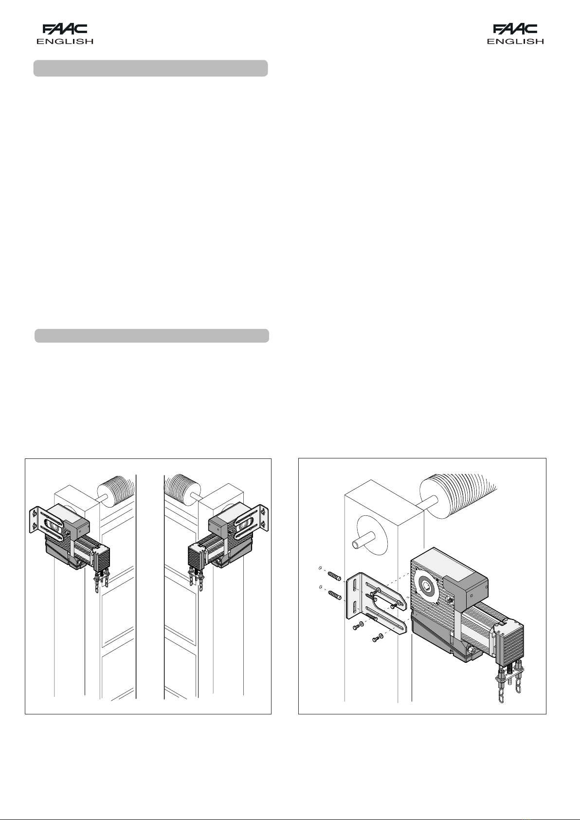
DESCRIPTION
The5413phautomatedsystemsareidealforactivatingbalanced
industrialsectionaldoors.
They consist of an electro-mechanical operator and remote
electronic control equipment. The non-reversing system ensures
mechanicallockingofthedoorwhenthemotorisnotoperating
and,therefore,nolockneedstobeinstalled.Operatorreleaseand
amanualmanoeuvringsystem(thelatterisonlysuppliedonthe
modelsforwhichitisspecified),makethedoormanoeuvrablein
theeventofapowercutormalfunction.
The door is normally closed; when opening is commanded, the
equipmentactivatestheelectricmotorwhichdrivesthedoorto
opening position to permit access. In “dead-man” systems, the
commandpush-buttonmustbekeptpressedforthewholeduration
oftheopeningorclosingmanoeuvre.
Intheautomaticallyoperatingsystems:
-Iftheautomaticlogicwasset,thedoorclosesafterpausetime
haselapsed.
-Ifthesemi-automaticlogicwasset,asecondpulsemustbesent
toclosethedoor.
-Astoppulse(ifsupplied)alwaysstopsmovement.
Forfulldetails on thebehaviour oftheautomated systemin the
differentlogics,consulttheinstallationTechnician.
Automatedsystemsmayincludesafetydevices(sensitiveedges,
photocells)thatpreventthedoorfromclosingand/oropeningwhen
thereisanobstacleintheareatheyprotect.Emergencymanual
openingispossiblebyusingthereleasesystem.
Manualcommandispossiblebyactivatingthechain-operated
winch(formodelswithwhichitissupplied).
Electriccommandisdisabledduringthemanualmanoeuvreor
whentheoperatorisreleased.
Thewarning-light,wheresupplied,indicatesthatthedooriscur-
rentlymoving.
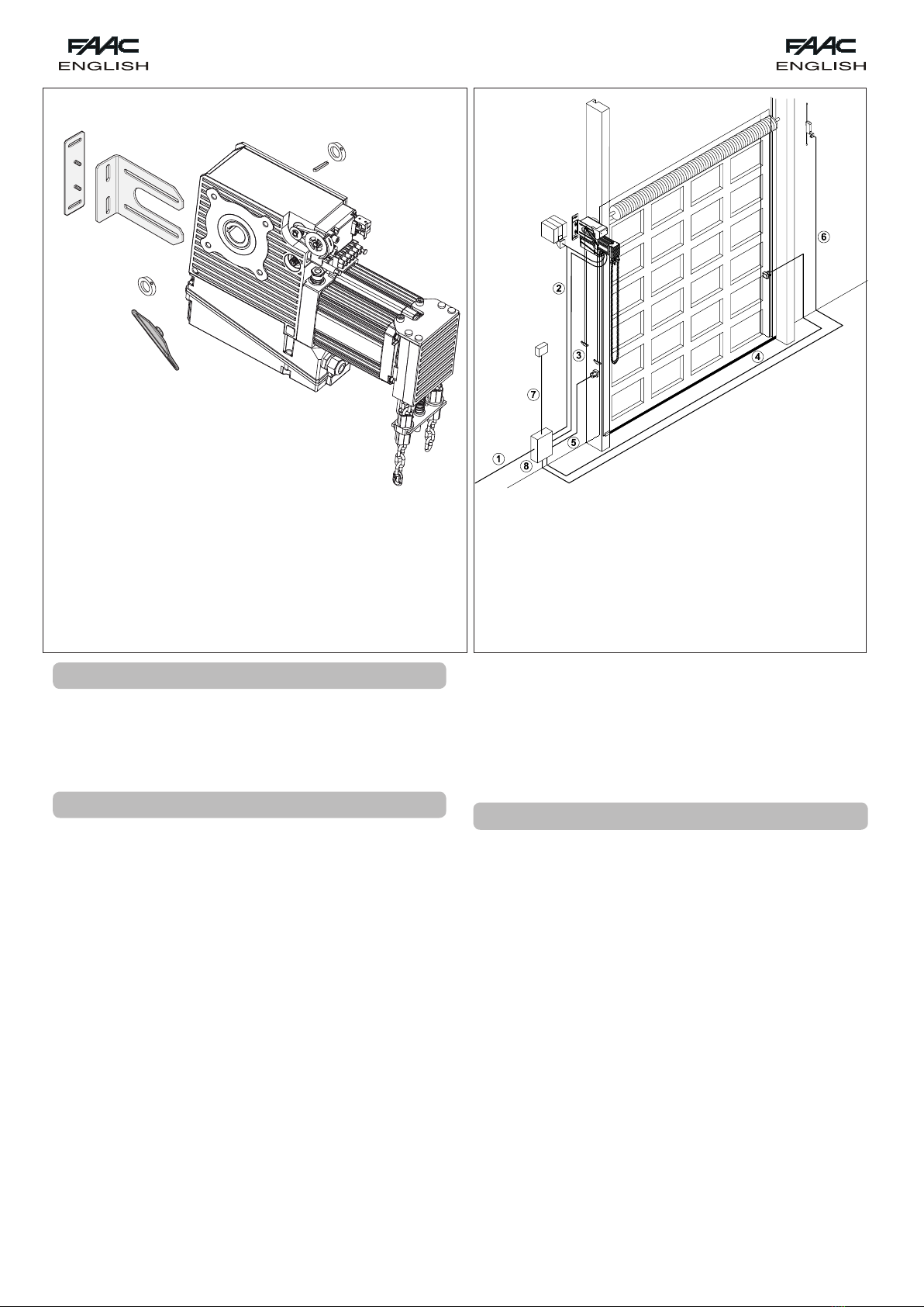
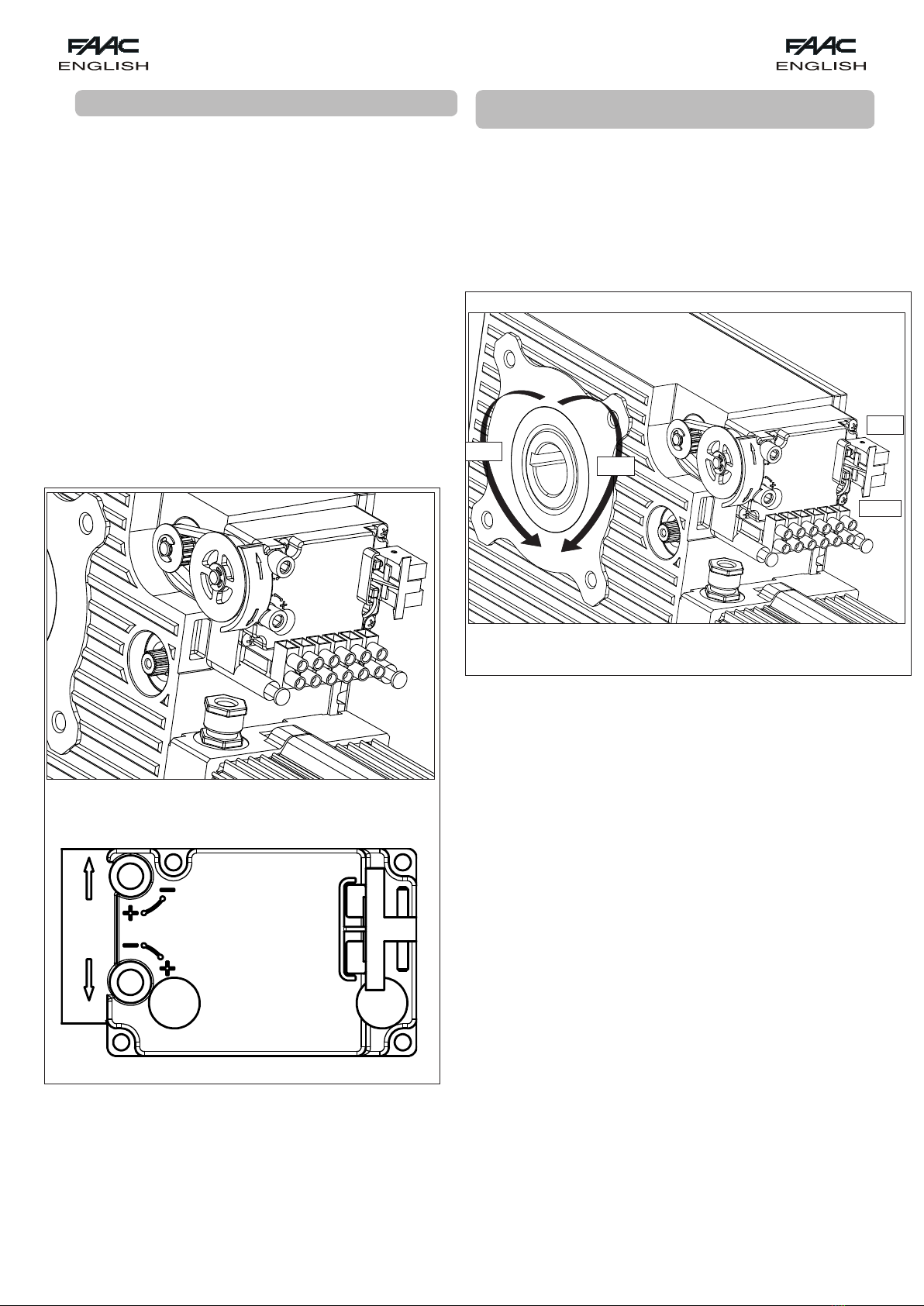
MANUAL OPERATION (541 3ph with winch)
If the door has to be activated and the automated system is
inactiveduetoapower-cutormalfunction,thedooropeningand
closingmanoeuvrescanbedonebyhand,byusingthechain-
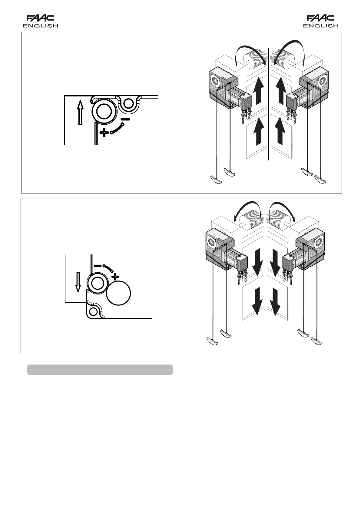
operatedwinch.Checktheindicatorsigntoseewhichbranchof
thechainhastobeactivatedtoperformtherequiredmanoeuvre.
Pulldownwardonlythebranchinvolved.
Ifnoindicatorsignispresent,pulloneofthechainbrancheswi-
thoutforcingandcheckifthedoortendstomoveintherequired
direction.Ifnot,activatetheotherbranch.
Whilethewinch isoperating,theoperator’selectrical controlis
disabled.
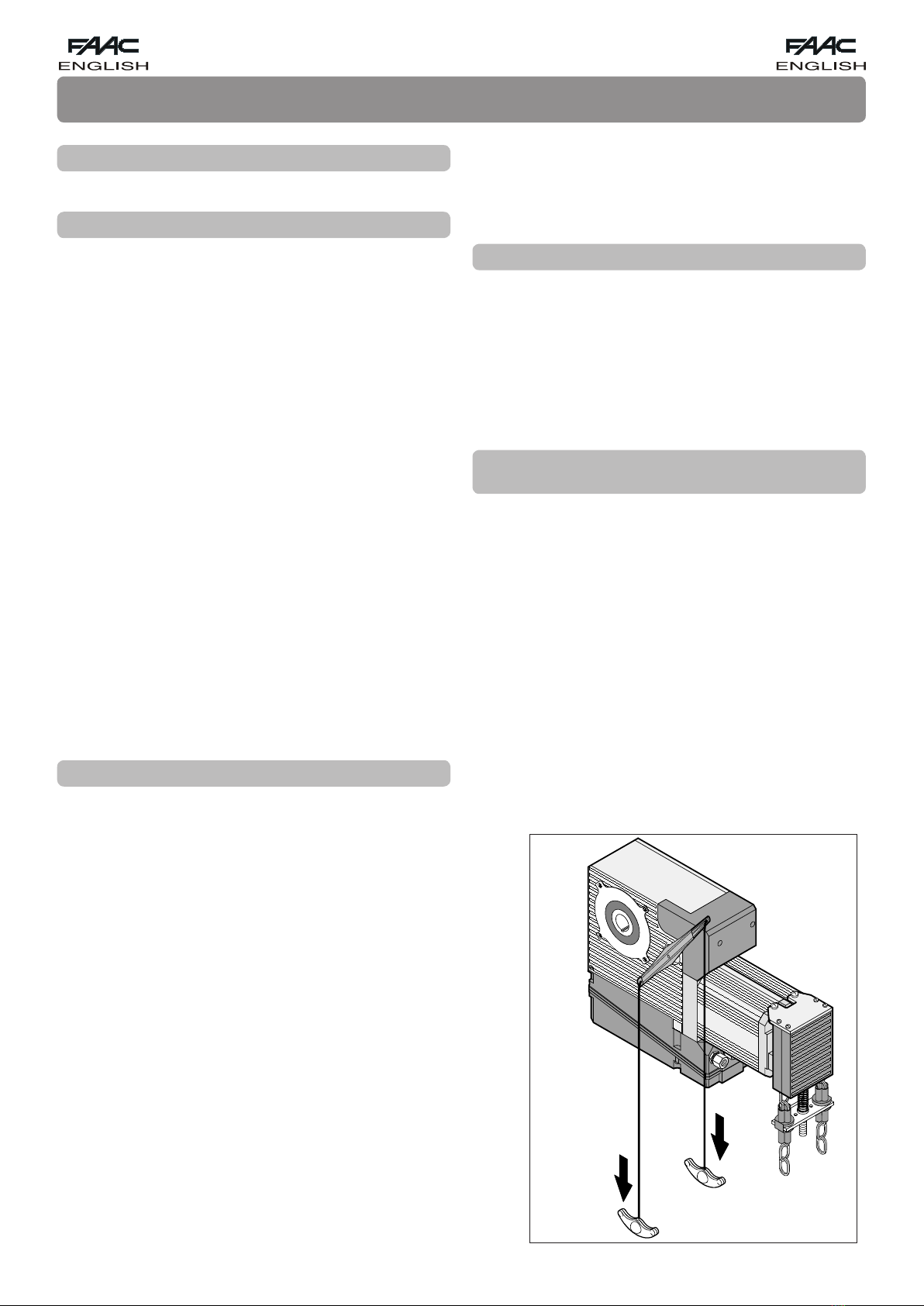
RELEASING THE OPERATOR AND RESTORING AUTO-
MATIC OPERATION
The5413phoperatorsareprovidedwithanemergencysystem
whichcanbeactivatedfromtheinside.
Theoperatorreleaseoperationmust be effectedwiththedoor
closedifpossible.Inanyevent,thepresenceofpersons,animals
andobjectsintheimmediatevicinityoftheoperatorisabsolutely
forbidden.
Ifthedoorhastobemovedmanuallyduetoapowercutormal-
functionoftheautomatedsystem,cutoutpowertothesystemand
usethereleasedeviceasfollows:releasetheoperatorbypulling
theropewiththeredknob(seefigure1)downwarduntilthelever
reachesthetravel-limitstop.Torestoreautomaticoperation,fully
closethedoorandpulltheropewiththegreenknobuntilthelever
returnstoitsoriginalposition.
Fig. 1