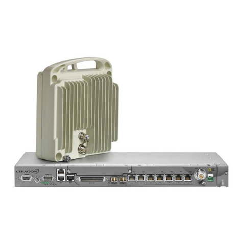
Ceragon FibeAir IP-20G User manual

Copyright © 2014 by Ceragon Networks Ltd. All rights reserved.
FibeAir® IP-20G
Installation Guide
DOC-00041192 Rev A.01
June 2014

FibeAir® IP-20G Installation Guide
Ceragon Proprietary and Confidential Page 2 of 36
Notice
This document contains information that is proprietary to Ceragon Networks Ltd. No part of this
publication may be reproduced, modified, or distributed without prior written authorization of
Ceragon Networks Ltd. This document is provided as is, without warranty of any kind.
Trademarks
Ceragon Networks®, FibeAir® and CeraView® are trademarks of Ceragon Networks Ltd.,
registered in the United States and other countries.
Ceragon® is a trademark of Ceragon Networks Ltd., registered in various countries.
CeraMap™, PolyView™, EncryptAir™, ConfigAir™, CeraMon™, EtherAir™, CeraBuild™, CeraWeb™,
and QuickAir™, are trademarks of Ceragon Networks Ltd.
Other names mentioned in this publication are owned by their respective holders.
Statement of Conditions
The information contained in this document is subject to change without notice. Ceragon
Networks Ltd. shall not be liable for errors contained herein or for incidental or consequential
damage in connection with the furnishing, performance, or use of this document or equipment
supplied with it.
Open Source Statement
The Product may use open source software, among them O/S software released under the GPL or
GPL alike license ("GPL License"). Inasmuch that such software is being used, it is released under
the GPL License, accordingly. Some software might have changed. The complete list of the
software being used in this product including their respective license and the aforementioned
public available changes is accessible on http://www.gnu.org/licenses/.
Information to User
Any changes or modifications of equipment not expressly approved by the manufacturer could
void the user’s authority to operate the equipment and the warranty for such equipment.

FibeAir® IP-20G Installation Guide
Ceragon Proprietary and Confidential Page 3 of 36
Table of Contents
1. FibeAir IP-20G Hardware Overview................................................................. 9
1.1 Ethernet Traffic Interfaces............................................................................................ 10
1.1.1 Ethernet Traffic Interface LEDs.................................................................................... 10
1.1.2 Ethernet Traffic Interface Pin-Outs .............................................................................. 11
1.2 Ethernet Management Interfaces................................................................................. 12
1.2.1 Management Interface Cable Options......................................................................... 12
1.2.2 Management Interface LEDs ....................................................................................... 12
1.2.3 Management Interface Pin-Outs.................................................................................. 13
1.3 TDM Interfaces (E1/DS1 1x16) (Optional)................................................................... 13
1.3.1 E1/DS1 Interface LEDs................................................................................................ 13
1.3.2 E1/DS1 Interface Pin-Outs........................................................................................... 14
1.4 Radio Interfaces........................................................................................................... 16
1.4.1 Radio Interface LEDs................................................................................................... 16
1.5 Power Interfaces.......................................................................................................... 18
1.5.1 Power Interface LEDs.................................................................................................. 18
1.6 Synchronization Interface............................................................................................. 19
1.6.1 Synchronization Interface LEDs................................................................................... 19
1.6.2 Synchronization Interface Pin-Outs ............................................................................. 20
1.7 Terminal Interface........................................................................................................ 20
1.7.1 Terminal Interface Pin-Outs......................................................................................... 20
1.8 External Alarms............................................................................................................ 21
1.8.1 External Alarm Pin-Outs............................................................................................... 21
1.9 Unit/ACT LED............................................................................................................... 22
2. Preparing for Installation ............................................................................... 23
2.1 Transportation/Storage ................................................................................................ 23
2.2Inspection..................................................................................................................... 23
2.3 Unpacking Equipment at the Site................................................................................. 23
3. Installing the IP-20G IDU................................................................................ 25
3.1 Kits required to perform the installation ....................................................................... 25
3.2 Tools............................................................................................................................. 25
3.3 Installing the IP-20G IDU in the Rack (19") ................................................................. 25
3.4 Grounding the IP-20G.................................................................................................. 26
3.5 Replacing an IP-20G IDU or SM-Card......................................................................... 27
4. Connecting the Power Cable......................................................................... 29
4.1 Power Supply Notes..................................................................................................... 31
5. Performing Initial Configuration.................................................................... 32
5.1 Establishing a Connection ........................................................................................... 32
5.1.1 Connecting to the Unit with a Serial Connection ......................................................... 32

FibeAir® IP-20G Installation Guide
Ceragon Proprietary and Confidential Page 4 of 36
5.1.2 Connecting to the Unit with a LAN Connection............................................................ 33
5.2 Logging On................................................................................................................... 33
5.3 Configuration................................................................................................................ 34
6. Specifications................................................................................................. 35
6.1 Environmental Specifications for IDU .......................................................................... 35
6.2 Environmental Specifications for RFU ......................................................................... 35
6.3 Mechanical Specifications............................................................................................ 35
6.4 Power Consumption Specifications ............................................................................. 36

FibeAir® IP-20G Installation Guide
Ceragon Proprietary and Confidential Page 5 of 36
Safety Precautions & Declared Material
General Equipment Precautions
Use of controls, adjustments, or performing procedures other than those
specified herein, may result in hazardous radiation exposure.
When working with a FibeAir IDU, note the following risk of electric
shock and energy hazard: Disconnecting one power supply disconnects
only one power supply module. To isolate the unit completely,
disconnect all power supplies.
Machine noise information order - 3. GPSGV, the highest sound pressure
level amounts to 70 dB (A) or less, in accordance with ISO EN 7779.
Static electricity may cause body harm, as well as harm to electronic
components inside the device.
To prevent damage, before touching components inside the device, all
electrostatic must be discharged from both personnel and tools.
High Frequency Electromagnetic Fields!
Exposure to strong high frequency electromagnetic fields may cause thermal
damage to personnel. The eye (cornea and lens) is easily exposed.
Any unnecessary exposure is undesirable and should be avoided.
In radio-relay communication installations, ordinary setup for normal
operation, the general RF radiation level will be well below the safety limit.
In the antennas and directly in front of them the RF intensity normally will
exceed the danger level, within limited portions of space.
Dangerous radiation may be found in the neighborhood of open waveguide
flanges or horns where the power is radiated into space.
To avoid dangerous radiation the following precautions must be taken:
During work within and close to the front of the antenna; make sure that
transmitters will remain turned off.
Before opening coaxial - or waveguide connectors carrying RF power, turn
off transmitters.
Consider any incidentally open RF connector as carrying power, until
otherwise proved. Do not look into coaxial connectors at closer than reading
distance (1 foot). Do not look into an open waveguide unless you are
absolutely sure that the power is turned off.
!!
!!
!!
!!

FibeAir® IP-20G Installation Guide
Ceragon Proprietary and Confidential Page 6 of 36
ESD
This equipment contains components which are sensitive to "ESD" (Electro
Static Discharge). Therefore, ESD protection measures must be observed
when touching the IDU.
Anyone responsible for the installation or maintenance of the FibeAir IDU
must use an ESD Wrist Strap.
Additional precautions include personnel grounding, grounding of work
bench, grounding of tools and instruments as well as transport and storage in
special antistatic bags and boxes.
Laser
Use of controls or adjustments or performance of procedures other than those
specified herein may result in hazardous radiation exposure.
The optical interface must only be serviced by qualified personnel, who are
aware of the hazards involved to repair laser products.
When handling laser products the following precautions must be taken:
Never look directly into an open connector or optical cable.
Before disconnecting an optical cable from the optical transmitter, the
power should be switched off. If this is not possible, the cable must be
disconnected from the transmitter before it is disconnected from the
receiver.
When the cable is reconnected it must be connected to the receiver before it
is connected to the transmitter.
Grounding: This equipment is designed to permit connection between the
earthed conductor of the DC supply circuit and the earthing conductor at the
equipment.
Note: This equipment has been tested and found to comply with
the limits for a Class A digital device, pursuant to part 15 of
the FCC rules. These limits are designed to provide
reasonable protection against harmful interference when
the equipment is operated in a commercial environment.
This equipment generates, uses, and can radiate radio
frequency energy and, if not installed and used in
accordance with the instruction manual, may cause harmful
interference to radio communications. Operation of this
equipment in a residential area is likely to cause harmful
interference in which case the user will be required to
correct the interference at his own expense.
Restricted Access Area: DC powered equipment should only be installed in a
Restricted Access Area.
Installation Codes: The equipment must be installed according to country
national electrical codes. For North America, equipment must be installed in
accordance to the US National Electrical Code, Articles 110-16, 110-17 and
110-18, and the Canadian Electrical Code, Section 12.
!!

FibeAir® IP-20G Installation Guide
Ceragon Proprietary and Confidential Page 7 of 36
Overcurrent Protection: A readily accessible listed branch circuit
overcurrent protective device, rated 15 A, must be incorporated in the
building wiring.
Grounded Supply System: The equipment shall be connected to a properly
grounded supply system. All equipment in the immediate vicinity shall be
grounded the same way, and shall not be grounded elsewhere.
Local Supply System: The DC supply system is to be local, i.e. within the same
premises as the equipment.
Disconnect Device: A disconnect device is not allowed in the grounded circuit
between the DC supply source and the frame/grounded circuit connection.
RoHS Compliance Declaration
Electronic Information Products Declaration of Hazardous/Toxic Substances
Component
Hazardous Substance
Lead
(Pb)
Mercury
(Hg)
Cadmium
(Cd)
Hexavalent
Chromium
(Cr VI)
Polybrominated
Biphenyls
(PBB)
Polybrominated
Diphenyl
Ethers (PBDE)
PCB/Circuit
Modules
Comply
Comply
Comply
Comply
Comply
Comply
Mechanical
Parts
Comply
Comply
Comply
Comply
Comply
Comply
Cables
Comply
Comply
Comply
Comply
Comply
Comply

FibeAir® IP-20G Installation Guide
Ceragon Proprietary and Confidential Page 8 of 36
About This Guide
This guide describes the FibeAir IP-20G installation procedures. This guide
also provides initial configuration instructions for once the hardware
installation is complete.
What You Should Know
An IP-20G system consists of an IP-20G indoor unit (IDU) and one or more
radio frequency units (RFUs). This manual provides instructions for the
installation of the IP-20G IDU only. Some features described in this manual
may not be available in the current release. Consult the Release Notes for the
functionality supported in the specific release you are using.
Target Audience
This guide is intended for use by personnel of all levels certified by Ceragon
personnel such as system engineers, technicians, or supervisors.
Related Documents
IP-20G Technical Description
IP-20G User Guide, DOC-00041190
IP-20G MIB Reference, DOC-00041191
FibeAir RFU-C Installation Guide, DOC-00017708
Ceragon License Management System, DOC-00019183

FibeAir® IP-20G Installation Guide
Ceragon Proprietary and Confidential Page 9 of 36
1. FibeAir IP-20G Hardware Overview
FibeAir IP-20G is a compact unit that fits in a single rack unit, with a passive
cooling system that eliminates the need for fans. An IP-20G system consists of
an IP-20G indoor unit (IDU) and one or two radio frequency units (RFUs). A
coaxial cable connects the IDU to each RFU, transmits traffic and management
data between the IDU and the RFU, and provides DC -48V power to the RFU.
An IP-20G IDU contains six Ethernet interfaces, one or two radio interfaces
depending on the hardware configuration, and optionally a 16 x E1/DS1
interface.
The IDU also includes two FE management interfaces, a DB9 dry contact
external alarms interface, an RJ-45 synchronization interface, and an RJ-45
terminal console interface for connection to a local craft terminal.
IP-20G receives an external supply of -48V, with an optional second power
interface for power redundancy.
The following hardware assembly options are available for the IP-20G IDU:
One or two radio interfaces
One or two power interfaces
With or without 16 x E1/DS1 interfaces
IP-20G Front Panel and Interfaces

FibeAir® IP-20G Installation Guide
Ceragon Proprietary and Confidential Page 10 of 36
1.1 Ethernet Traffic Interfaces
The front panel of the FibeAir IP-20G contains four electrical and two optical
GE Ethernet traffic interfaces:
2 x GE dual mode electrical or cascading interfaces (RJ-45) –GbE1/CS1,
GbE2/CS2
2 x GE electrical interfaces (RJ-45) –GbE3, GbE4
2 x GE optical interfaces (SFP) –SFP5, SFP6
1.1.1 Ethernet Traffic Interface LEDs
Each electrical interface has the following LEDs:
Port Status LED –Located on the upper left of each interface. Indicates the
link status of the interface, as follows:
Off –The interface is shut down or the signal is lost.
Green –The interface is enabled and the link is operational.
Blinking Green –The interface is transmitting and/or receiving traffic.
Port Rate LED –Located on the upper right of each interface. Indicates the
speed of the interface, as follows:
Off –100Base-TX
Green –1000Base-T
Blinking Green –10Base-T
Electrical GE Interface LEDs

FibeAir® IP-20G Installation Guide
Ceragon Proprietary and Confidential Page 11 of 36
Each optical interface has the following LED:
Port Status LED –A Port Status LED is located on the lower left of SFP5
and the lower right of SFP6. Each LED indicates the link status of the
interface, as follows:
Off –The interface is shut down or the signal is lost.
Green –The interface is enabled and the link is operational.
Blinking Green –The interface is transmitting and/or receiving traffic.
Optical GE Interface LED
1.1.2 Ethernet Traffic Interface Pin-Outs
GbE Interface Pin-Out Diagram (GbE1, GbE2, GbE3, GbE4)
RJ45
Pin no.
Description
1
BI_DA+ (Bi-directional pair +A)
2
BI_DA- (Bi-directional pair -A)
3
BI_DB+ (Bi-directional pair +B)
4
BI_DC+ (Bi-directional pair +C)
5
BI_DC- (Bi-directional pair -C)
6
BI_DB- (Bi-directional pair +B)
7
BI_DD+ (Bi-directional pair +D)
8
BI_DD- (Bi-directional pair -D)

FibeAir® IP-20G Installation Guide
Ceragon Proprietary and Confidential Page 12 of 36
1.2 Ethernet Management Interfaces
FibeAir IP-10G contains two FE management interfaces, which connect to a
single RJ-45 physical connector on the front panel (MGMT).
Management Interface Pin Connections
Management Switch
TX+
TX-
RX+
RX-
TX+
TX-
RX+
RX-
Port 1
Port 2
1
2
3
4
5
6
7
8
RJ-45 Connector
(female)
1.2.1 Management Interface Cable Options
If the user only needs to use a single management interface, a standard Cat5
RJ-45 cable (straight or cross) can be connected to the MGMT interface.
To access both management interfaces, a special 2 x FE splitter cable can be
ordered from Ceragon.
2 x FE Splitter Cable Marketing Model
Marketing Model
Marketing Description
Part Number
FE-SPL-1xRJ45F-to-2xRJ45F
CONN,ADAPTER,RJ-45 SPLIT ,1X2 FEMALE
NM-0177-0
1.2.2 Management Interface LEDs
The MGMT interface has the following LEDs:
Port Status LED –The LED for management interface 1 is located on the
upper left of the MGMT interface. The LED for management interface 2 is
located on the upper right of the MGMT interface. Each LED indicates the
link status of the interface, as follows:
Off –The cable is not connected or the signal is lost.
Note: The management interfaces cannot be shut down.
Green –The interface is enabled and the link is operational.
Blinking Green –The interface is transmitting and/or receiving
management traffic.

FibeAir® IP-20G Installation Guide
Ceragon Proprietary and Confidential Page 13 of 36
Management FE Interface LEDs
1.2.3 Management Interface Pin-Outs
Management Interface Pin-Out Diagram (MGMT)
RJ45
Pin no.
Description
1
Port 1 –TX+
2
Port 1 –TX-
3
Port 1 –RX+
4
Port 2 –TX+
5
Port 2 –TX-
6
Port 1 –RX-
7
Port 2 –RX+
8
Port 2 –RX-
1.3 TDM Interfaces (E1/DS1 1x16) (Optional)
Optionally, FibeAir IP-20G can be ordered with an MDR69 connector in which
16 E1/DS1 interfaces are available (ports 1 through 16).
1.3.1 E1/DS1 Interface LEDs
The E1/DS1 interface has the following LEDs
ACT LED –Indicates whether the TDM card is working properly (Green)
or if there is an error or a problem with the card’s functionality (Red).
E1/DS1 LED –Indicates whether the interfaces are enabled with no
alarms (Green), with alarms (Red), or no interfaces enabled (Off).

FibeAir® IP-20G Installation Guide
Ceragon Proprietary and Confidential Page 14 of 36
TDM Interface LEDs
1.3.2 E1/DS1 Interface Pin-Outs
The16 x E1/DS1 connector is a SCSI 68-pin connector.
E1/DS1 Interface Pin-Out Diagram (E1/DS1 1-16)
Pin #
Signal
Label on the
Twisted Pair
Type
1
OUT - TIP1
Ch1 Tx
TWISTED PAIR
35
OUT - RING1
2
OUT - TIP2
Ch2 Tx
TWISTED PAIR
36
OUT - RING2
3
OUT - TIP3
Ch3 Tx
TWISTED PAIR
37
OUT - RING3
4
OUT - TIP4
Ch4 Tx
TWISTED PAIR
38
OUT - RING4
5
OUT - TIP5
Ch5 Tx
TWISTED PAIR
39
OUT - RING5
6
OUT - TIP6
Ch6 Tx
TWISTED PAIR
40
OUT - RING6
7
OUT - TIP7
Ch7 Tx
TWISTED PAIR
41
OUT - RING7
8
OUT - TIP8
Ch8 Tx
TWISTED PAIR
42
OUT - RING8
9
OUT - TIP9
Ch9 Tx
TWISTED PAIR
43
OUT - RING9
10
OUT - TIP10
Ch10 Tx
TWISTED PAIR
44
OUT - RING10
11
OUT - TIP11
Ch11 Tx
TWISTED PAIR

FibeAir® IP-20G Installation Guide
Ceragon Proprietary and Confidential Page 15 of 36
Pin #
Signal
Label on the
Twisted Pair
Type
45
OUT - RING11
12
OUT - TIP12
Ch12 Tx
TWISTED PAIR
46
OUT - RING12
13
OUT - TIP13
Ch13 Tx
TWISTED PAIR
47
OUT - RING13
14
OUT - TIP14
Ch14 Tx
TWISTED PAIR
48
OUT - RING14
15
OUT - TIP15
Ch15 Tx
TWISTED PAIR
49
OUT - RING15
16
OUT - TIP16
Ch16 Tx
TWISTED PAIR
50
OUT - RING16
19
IN - TIP1
Ch1 Rx
TWISTED PAIR
53
IN - RING1
20
IN - TIP2
Ch2 Rx
TWISTED PAIR
54
IN - RING2
21
IN - TIP3
Ch3 Rx
TWISTED PAIR
55
IN - RING3
22
IN - TIP4
Ch4 Rx
TWISTED PAIR
56
IN - RING4
23
IN - TIP5
Ch5 Rx
TWISTED PAIR
57
IN - RING5
24
IN - TIP6
Ch6 Rx
TWISTED PAIR
58
IN - RING6
25
IN - TIP7
Ch7 Rx
TWISTED PAIR
59
IN - RING7
26
IN - TIP8
Ch8 Rx
TWISTED PAIR
60
IN - RING8
27
IN - TIP9
Ch9 Rx
TWISTED PAIR
61
IN - RING9
28
IN - TIP10
Ch10 Rx
TWISTED PAIR
62
IN - RING10
29
IN - TIP11
Ch11 Rx
TWISTED PAIR

FibeAir® IP-20G Installation Guide
Ceragon Proprietary and Confidential Page 16 of 36
Pin #
Signal
Label on the
Twisted Pair
Type
63
IN - RING11
30
IN - TIP12
Ch12 Rx
TWISTED PAIR
64
IN - RING12
31
IN - TIP13
Ch13 Rx
TWISTED PAIR
65
IN - RING13
32
IN - TIP14
Ch14 Rx
TWISTED PAIR
66
IN - RING14
33
IN - TIP15
Ch15 Rx
TWISTED PAIR
67
IN - RING15
34
IN - TIP16
Ch16 Rx
TWISTED PAIR
68
IN - RING16
17
SHELL
-
SHIELD
18
SHELL
-
SHIELD
51
SHELL
-
SHIELD
52
SHELL
-
SHIELD
1.4 Radio Interfaces
FibeAir IP-20G includes one or two radio interfaces, depending on the
hardware assembly option that was selected. Each radio interface uses a TNC
connector type. Each radio interface is connected to an RFU via coaxial cable.
This connection is used for traffic between the RFU and the IDU. It is also used
to provide -48V DC power from the IDU to the RFU, as well as for management
and configuration of the RFU.
The radio interfaces are labeled Radio 1 and, if there is a second radio
interface, Radio 2.
1.4.1 Radio Interface LEDs
Each radio interface has the following set of LEDs. The LEDs for Radio 1 are
located to the right of the interface. The LEDs for Radio 2 are located to the left
of the interface.
The LEDs indicate the following:
ACT –Indicates whether the interface is working properly (Green) or if
there is an error or a problem with the interface’s functionality (Red), as
follows:
Off –The radio is disabled.
Green –The radio is active and operating normally.

FibeAir® IP-20G Installation Guide
Ceragon Proprietary and Confidential Page 17 of 36
Blinking Green –The radio is operating normally and is in standby
mode.
Red –There is a hardware failure.
Blinking Red –Troubleshooting mode.
LINK –Indicates the status of the radio link, as follows:
Green –The radio link is operational.
Red –There is an LOF or Excessive BER alarm on the radio.
Blinking Green –An IF loopback is activated, and the result is OK.
Blinking Red –An IF loopback is activated, and the result is Failed.
RFU –Indicates the status of the RFU, as follows:
Green –The RFU is functioning normally.
Yellow –A minor RFU alarm or a warning is present, or the RFU is in
TX mute mode, or, in a protected configuration, the RFU is in standby
mode.
Red –A cable is disconnected, or a major or critical RFU alarm is
present.
Blinking Green –An RF loopback has been activated, and the result is
OK.
Blinking Red –An RF loopback has been activated, and the result is
Failed.
Radio Interface LEDs

FibeAir® IP-20G Installation Guide
Ceragon Proprietary and Confidential Page 18 of 36
1.5 Power Interfaces
FibeAir IP-20G receives an external supply of -48V current via one or two
power interfaces (the second power interface is optional for power
redundancy). The IP-20G monitors the power supply for under-voltage and
includes reverse polarity protection, so that if the positive (+) and negative (-)
inputs are mixed up, the system remains shutdown.
The allowed power input range for the IP-20G is -40V to -60V. An under
voltage alarm is triggered if the power goes below the allowed range, and an
over voltage alarm is triggered if the power goes above the allowed range.
1.5.1 Power Interface LEDs
There is an ACT LED for each power interface. The LED is Green when the
voltage being fed to the power interface is within range, and Red if the voltage
is not within range or if a power cable is not connected.
Power Interface LEDs

FibeAir® IP-20G Installation Guide
Ceragon Proprietary and Confidential Page 19 of 36
1.6 Synchronization Interface
FibeAir IP-20G includes an RJ-45 synchronization interface for T3 clock input
and T4 clock output. The interface is labeled SYNC.
1.6.1 Synchronization Interface LEDs
The synchronization interface contains two LEDs, one on the upper left of the
interface and one on the upper right of the interface, as follows:
T3 Status LED –Located on the upper left of the interface. Indicates the
status of T3 input clock, as follows:
Off –There is no T3 input clock, or the input is illegal.
Green –There is legal T3 input clock.
T4 Status LED –Located on the upper right of the interface. Indicates the
status of T4 output clock, as follows:
Off –T4 output clock is not available.
Green –T4 output clock is available.
Blinking Green –The clock unit is in a holdover state.
Sync Interface LEDs

FibeAir® IP-20G Installation Guide
Ceragon Proprietary and Confidential Page 20 of 36
1.6.2 Synchronization Interface Pin-Outs
Synchronization Interface Pin-Out Diagram
1.7 Terminal Interface
FibeAir IP-20G includes an RJ-45 terminal interface (RS-232). A local craft
terminal can be connected to the terminal interface for local CLI management
of the unit.
1.7.1 Terminal Interface Pin-Outs
Terminal Interface Pin-Out Diagram
RJ45
Pin no.
Description
1
NC
2
NC
3
NC
4
GND
5
Terminal-RX (System TX)
6
Terminal-TX (System RX)
7
NC
8
NC
RJ45
Pin no.
Description
1
T3_IN_N
2
T3_IN_P
3
1PPS_P
4
T4_OUT_N
5
T4_OUT_P
6
1PPS_N
7
ToD_P (or PPS_IN_P)
8
ToD_N (or PPS_IN_N)
Other manuals for FibeAir IP-20G
3
Table of contents
Other Ceragon Network Hardware manuals

Ceragon
Ceragon FibeAir IP-20C User manual

Ceragon
Ceragon FibeAir IP-20F User manual

Ceragon
Ceragon FibeAir IP-20G User manual

Ceragon
Ceragon FibeAir IP-20 All-Outdoor Series User manual

Ceragon
Ceragon Fibe-Air IP-10G User manual

Ceragon
Ceragon FibeAir IP-20G User manual

Ceragon
Ceragon FibeAir IP-20G Parts list manual
Popular Network Hardware manuals by other brands

Cisco
Cisco CGR 1000 Series Getting connected guide

Matrix Switch Corporation
Matrix Switch Corporation MSC-HD161DEL product manual

National Instruments
National Instruments NI 653x user manual

B&B Electronics
B&B Electronics ZXT9-IO-222R2 product manual

Yudor
Yudor YDS-16 user manual

D-Link
D-Link ShareCenter DNS-320L datasheet