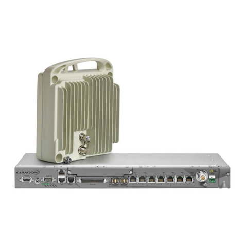
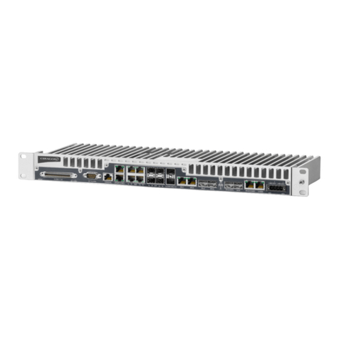
Ceragon FibeAir IP-20G Parts list manual

ETSI Version
Copyright © 2014 by Ceragon Networks Ltd. All rights reserved.
FibeAir®IP-20G
Technical Description
November 2014
Release: 7.9
Document Revision A.05

FibeAir® IP-20G Technical Description
Ceragon Proprietary and Confidential Page 2 of 266
Notice
This document contains information that is proprietary to Ceragon Networks Ltd. No part of this
publication may be reproduced, modified, or distributed without prior written authorization of
Ceragon Networks Ltd. This document is provided as is, without warranty of any kind.
Trademarks
Ceragon Networks®, FibeAir® and CeraView® are trademarks of Ceragon Networks Ltd.,
registered in the United States and other countries.
Ceragon® is a trademark of Ceragon Networks Ltd., registered in various countries.
CeraMap™, PolyView™, EncryptAir™, ConfigAir™, CeraMon™, EtherAir™, CeraBuild™, CeraWeb™,
and QuickAir™, are trademarks of Ceragon Networks Ltd.
Other names mentioned in this publication are owned by their respective holders.
Statement of Conditions
The information contained in this document is subject to change without notice. Ceragon
Networks Ltd. shall not be liable for errors contained herein or for incidental or consequential
damage in connection with the furnishing, performance, or use of this document or equipment
supplied with it.
Open Source Statement
The Product may use open source software, among them O/S software released under the GPL or
GPL alike license ("GPL License"). Inasmuch that such software is being used, it is released under
the GPL License, accordingly. Some software might have changed. The complete list of the
software being used in this product including their respective license and the aforementioned
public available changes is accessible on http://www.gnu.org/licenses/.
Information to User
Any changes or modifications of equipment not expressly approved by the manufacturer could
void the user’s authority to operate the equipment and the warranty for such equipment.

FibeAir® IP-20G Technical Description
Ceragon Proprietary and Confidential Page 3 of 266
Table of Contents
1. Synonyms and Acronyms.............................................................................. 14
2. Introduction .................................................................................................... 17
2.1 Product Overview......................................................................................................... 18
2.1.1 IP-20G Radio Options.................................................................................................. 19
2.1.2 IP-20G Highlights......................................................................................................... 20
2.1.3IP-20G Protection Options........................................................................................... 20
2.2 Reference Configurations ............................................................................................ 21
2.2.1 FibeAir IP-20 Platform Reference Topology................................................................ 21
2.2.2 Dual Modem Activation................................................................................................ 22
2.2.3 IDU Cascading with Dual Modems .............................................................................. 23
2.2.4 Chained Network.......................................................................................................... 24
2.2.5 Ring with Spur.............................................................................................................. 25
2.2.6 Aggregation/POP Site.................................................................................................. 26
2.3 New Features in Version T7.9 ..................................................................................... 27
3. IDU Hardware Description ............................................................................. 29
3.1 Hardware Architecture ................................................................................................. 30
3.2 Front Panel Description................................................................................................ 32
3.3 Ethernet Traffic Interfaces............................................................................................ 33
3.4 Ethernet Management Interfaces................................................................................. 35
3.5 E1 Interface (Optional)................................................................................................. 37
3.6 Radio Interfaces........................................................................................................... 38
3.7 Power Interfaces.......................................................................................................... 40
3.8 Synchronization Interface............................................................................................. 41
3.9 Terminal Interface........................................................................................................ 42
3.10 Unit/ACT LED............................................................................................................... 42
3.11 External Alarms............................................................................................................ 43
3.12 Storage Memory Card.................................................................................................. 44
4. RFU Hardware Description and Branching Options .................................... 45
4.1 RFU Overview.............................................................................................................. 46
4.2 RFU Selection Guide ................................................................................................... 47
4.3 RFU-C.......................................................................................................................... 48
4.3.1 Main Features of RFU-C.............................................................................................. 48
4.4 1500HP/RFU-HP.......................................................................................................... 49
4.4.1 Main Features of 1500HP/RFU-HP ............................................................................. 49
4.4.2 1500HP/RFU-HP Functional Block Diagram and Concept of Operation..................... 51
4.4.3 1500HP/RFU-HP Comparison Table........................................................................... 53
4.4.4 1500HP/RFU-HP System Configurations.................................................................... 53
4.4.5 Space Diversity with IF Combining .............................................................................. 54

FibeAir® IP-20G Technical Description
Ceragon Proprietary and Confidential Page 4 of 266
4.4.6 Split Mount Configuration and Branching Network...................................................... 54
4.4.7 1500HP/RFU-HP Models and Part Numbers............................................................... 59
4.4.8 OCB Part Numbers...................................................................................................... 59
5. Activation Keys............................................................................................... 61
5.1 Working with Activation Keys....................................................................................... 62
5.2 Demo Mode.................................................................................................................. 62
5.3 Activation Key-Enabled Features................................................................................. 62
6. Feature Description........................................................................................ 66
6.1 Innovative Techniques to Boost Capacity and Reduce Latency ................................. 67
6.1.1 Capacity Summary....................................................................................................... 68
6.1.2 Header De-Duplication................................................................................................. 69
6.1.3 Latency......................................................................................................................... 72
6.1.4 Frame Cut-Through...................................................................................................... 73
6.2 Radio Features............................................................................................................. 75
6.2.1 Adaptive Coding Modulation (ACM)............................................................................. 76
6.2.2 Cross Polarization Interference Canceller (XPIC) ....................................................... 79
6.2.3 1+1 HSB Radio Protection........................................................................................... 82
6.2.4 ATPC............................................................................................................................ 84
6.2.5 Multi-Carrier ABC......................................................................................................... 85
6.2.6 BBS Space Diversity.................................................................................................... 87
6.2.7 Radio Utilization PMs................................................................................................... 89
6.3 Ethernet Features ........................................................................................................ 90
6.3.1 Ethernet Services Overview......................................................................................... 91
6.3.2 IP-20G’s Ethernet Capabilities ................................................................................... 106
6.3.3 Supported Standards ................................................................................................. 107
6.3.4 Ethernet Service Model.............................................................................................. 108
6.3.5 Ethernet Interfaces..................................................................................................... 125
6.3.6 Quality of Service (QoS) ............................................................................................ 134
6.3.7 Global Switch Configuration....................................................................................... 162
6.3.8 Automatic State Propagation ..................................................................................... 163
6.3.9 Network Resiliency..................................................................................................... 164
6.3.10OAM........................................................................................................................... 170
6.4 Synchronization.......................................................................................................... 173
6.4.1 Synchronization Overview.......................................................................................... 174
6.4.2 IP-20G Synchronization Solution............................................................................... 176
6.4.3 Available Synchronization Interfaces......................................................................... 177
6.4.4 Configuring Native Sync Distribution ......................................................................... 177
6.4.5 Native Sync Distribution Mode................................................................................... 179
6.4.6 SyncE PRC Pipe Regenerator Mode......................................................................... 183
6.4.7 SSM Support and Loop Prevention ........................................................................... 183
6.5 TDM Services............................................................................................................. 185
6.5.1 Native TDM Trails ...................................................................................................... 186
6.5.2 TDM Pseudowire........................................................................................................ 190
6.5.3 TDM Reference Solutions.......................................................................................... 196
7. FibeAir IP-20G Management........................................................................ 198
7.1 Management Overview.............................................................................................. 199
7.2 Automatic Network Topology Discovery with LLDP Protocol .................................... 200

FibeAir® IP-20G Technical Description
Ceragon Proprietary and Confidential Page 5 of 266
7.3 Management Communication Channels and Protocols............................................. 201
7.4 Web-Based Element Management System (Web EMS)........................................... 203
7.5 Command Line Interface (CLI)................................................................................... 204
7.6 Configuration Management........................................................................................ 204
7.7 Software Management............................................................................................... 205
7.7.1 Backup Software Version........................................................................................... 206
7.8 IPv6 Support .............................................................................................................. 207
7.9 In-Band Management................................................................................................. 207
7.10 Local Management..................................................................................................... 207
7.11 Alarms........................................................................................................................ 208
7.11.1Configurable RSL Threshold Alarms and Traps........................................................ 208
7.11.2Alarms Editing............................................................................................................ 208
7.12 External Alarms.......................................................................................................... 209
7.13 NTP Support .............................................................................................................. 209
7.14 UTC Support .............................................................................................................. 209
7.15 System Security Features.......................................................................................... 210
7.15.1Ceragon’s Layered Security Concept ........................................................................ 210
7.15.2Defenses in Management Communication Channels................................................ 211
7.15.3Defenses in User and System Authentication Procedures........................................ 212
7.15.4Secure Communication Channels ............................................................................. 214
7.15.5Security Log ............................................................................................................... 216
8. Standards and Certifications....................................................................... 218
8.1 Supported Ethernet Standards .................................................................................. 219
8.2 MEF Certifications for Ethernet Services................................................................... 220
8.3 Supported TDM Pseudowire Encapsulations ............................................................ 221
8.4 Standards Compliance............................................................................................... 221
8.5 Network Management, Diagnostics, Status, and Alarms........................................... 222
9. Specifications............................................................................................... 223
9.1 General Radio Specifications..................................................................................... 224
9.2 Radio Capacity Specifications ................................................................................... 225
9.2.1 Radio Capacity Specifications (no XPIC)................................................................... 225
9.2.2 Radio Capacity Specifications with XPIC................................................................... 230
9.3 Transmit Power Specifications (dBm)........................................................................ 233
9.3.1 Transmit Power with RFU-C (dBm) ........................................................................... 233
9.3.2 Transmit Power with 1500HP/RFU-HP (dBm)........................................................... 234
9.4 Receiver Threshold (RSL) Specifications (dBm @ BER = 10-6)............................... 235
9.4.1 RFU-C Receiver Threshold (RSL) (dBm @ BER = 10-6).......................................... 235
9.4.2 Receiver Thresholds with RFU-HP............................................................................ 238
9.4.3 Receiver Thresholds with 1500HP............................................................................. 240
9.5 Frequency Bands....................................................................................................... 242
9.5.1 Frequency Bands –RFU-C and RFU-Ce .................................................................. 242

FibeAir® IP-20G Technical Description
Ceragon Proprietary and Confidential Page 6 of 266
9.5.2 Frequency Bands –1500HP and RFU-HP................................................................ 253
9.6 Mediation Device Losses........................................................................................... 254
9.6.1 RFU-C Mediation Device Losses............................................................................... 254
9.6.2 1500HP/RFU-HP Branching Network Losses............................................................ 255
9.7 Ethernet Latency Specifications................................................................................. 257
9.8 Ethernet Specifications .............................................................................................. 260
9.8.1 Ethernet Interface Specifications ............................................................................... 260
9.8.2 Carrier Ethernet Functionality .................................................................................... 260
9.9 TDM Specifications .................................................................................................... 261
9.9.1 E1 Cross Connect...................................................................................................... 261
9.9.2 E1 Interface Specifications ........................................................................................ 261
9.10 Synchronization Specifications .................................................................................. 261
9.11 Mechanical Specifications.......................................................................................... 262
9.12 Environmental Specifications..................................................................................... 263
9.12.1Environmental Specifications for IDU ........................................................................ 263
9.12.2Environmental Specifications for RFU ....................................................................... 263
9.13 Supported Antenna Types ......................................................................................... 264
9.13.1RFU-C Antenna Connection ...................................................................................... 264
9.13.21500HP/RFU-HP Antenna Connection...................................................................... 264
9.14 Waveguide Specifications.......................................................................................... 265
9.14.1RFU-C Waveguide Specifications.............................................................................. 265
9.14.21500HP/RFU-HP Waveguide Specifications............................................................. 265
9.15 Power Input Specifications......................................................................................... 266
9.16 Power Consumption Specifications ........................................................................... 266

FibeAir® IP-20G Technical Description
Ceragon Proprietary and Confidential Page 7 of 266
List of Figures
IP-20 Platform Reference Topology.................................................................... 21
Reference Configuration –Dual Modem Activation .......................................... 22
Reference Configuration –IDU Cascading with Dual Modems......................... 23
Reference Configuration –Chained Network..................................................... 24
Reference Configuration –Ring with Spur ........................................................ 25
Reference Configuration –Aggregation/POP Site............................................. 26
IP-20G Block Diagram.......................................................................................... 31
IP-20G Front Panel and Interfaces...................................................................... 32
Electrical GE Interface LEDs............................................................................... 33
Optical GE Interface LED..................................................................................... 34
Management Interface Pin Connections ............................................................ 35
Management FE Interface LEDs.......................................................................... 36
TDM Interface LEDs............................................................................................. 37
Radio Interface LEDs........................................................................................... 39
Power Interface LEDs.......................................................................................... 40
Sync Interface LEDs ............................................................................................ 41
Unit/ACT LED ....................................................................................................... 42
SM Card and Cover.............................................................................................. 44
1500HP 2RX in 1+0 SD Configuration................................................................. 51
1500HP 1RX in 1+0 SD Configuration................................................................. 51
All-Indoor Vertical Branching.............................................................................. 55
Split-Mount Branching and All-Indoor Compact................................................ 55
ld OCB .................................................................................................................. 56
OCB....................................................................................................................... 56
OCB and DCB Block Diagram............................................................................. 57
Header De-Duplication Potential Throughput Savings per Layer..................... 70
Propagation Delay with and without Frame Cut-Through................................. 73
Frame Cut-Through.............................................................................................. 74
Frame Cut-Through Operation............................................................................ 74
Adaptive Coding and Modulation with 10 Working Points................................ 77

FibeAir® IP-20G Technical Description
Ceragon Proprietary and Confidential Page 8 of 266
Dual Polarization.................................................................................................. 79
XPIC Implementation........................................................................................... 80
XPIC –Impact of Misalignments and Channel Degradation ............................. 80
Path Loss on Secondary Path of 1+1 HSB Protection Link .............................. 83
Multi-Carrier ABC Traffic Flow............................................................................ 85
Direct and Reflected Signals............................................................................... 87
1+1 BBS Space Diversity Configuration –Receiving Side................................ 88
Basic Ethernet Service Model............................................................................. 91
Ethernet Virtual Connection (EVC) ..................................................................... 92
Point to Point EVC ............................................................................................... 93
Multipoint to Multipoint EVC ............................................................................... 93
Rooted Multipoint EVC ........................................................................................ 93
MEF Ethernet Services Definition Framework................................................... 95
E-Line Service Type Using Point-to-Point EVC.................................................. 96
EPL Application Example.................................................................................... 97
EVPL Application Example.................................................................................. 97
E-LAN Service Type Using Multipoint-to-Multipoint EVC.................................. 98
Adding a Site Using an E-Line service............................................................... 99
Adding a Site Using an E-LAN service............................................................... 99
MEF Ethernet Private LAN Example ................................................................. 100
MEF Ethernet Virtual Private LAN Example ..................................................... 101
E-Tree Service Type Using Rooted-Multipoint EVC......................................... 101
E-Tree Service Type Using Multiple Roots....................................................... 102
MEF Ethernet Private Tree Example................................................................. 102
Ethernet Virtual Private Tree Example.............................................................. 103
Mobile Backhaul Reference Model ................................................................... 104
Packet Service Core Building Blocks............................................................... 104
IP-20G Services Model....................................................................................... 108
IP-20G Services Core......................................................................................... 109
IP-20G Services Flow......................................................................................... 110
Point-to-Point Service........................................................................................ 111

FibeAir® IP-20G Technical Description
Ceragon Proprietary and Confidential Page 9 of 266
Multipoint Service.............................................................................................. 112
Management Service ......................................................................................... 114
Management Service and its Service Points.................................................... 116
SAPs and SNPs.................................................................................................. 117
Pipe Service Points............................................................................................ 118
SAP, SNP and Pipe Service Points in a Microwave Network.......................... 118
Service Path Relationship on Point-to-Point Service Path ............................. 122
Physical and Logical Interfaces........................................................................ 125
Grouped Interfaces as a Single Logical Interface on Ingress Side ................ 126
Grouped Interfaces as a Single Logical Interface on Egress Side................. 126
Relationship of Logical Interfaces to the Switching Fabric ............................ 130
QoS Block Diagram............................................................................................ 134
Standard QoS and H-QoS Comparison............................................................ 136
Hierarchical Classification ................................................................................ 137
Classification Method Priorities........................................................................ 138
Ingress Policing Model...................................................................................... 142
IP-20G Queue Manager...................................................................................... 145
Synchronized Packet Loss................................................................................ 146
Random Packet Loss with Increased Capacity Utilization Using WRED ....... 147
WRED Profile Curve........................................................................................... 148
Detailed H-QoS Diagram.................................................................................... 151
Scheduling Mechanism for a Single Service Bundle....................................... 154
G.8032 Ring in Idle (Normal) State.................................................................... 165
G.8032 Ring in Protecting State........................................................................ 166
Load Balancing Example in G.8032 Ring......................................................... 166
IP-20G End-to-End Service Management ......................................................... 170
SOAM Maintenance Entities (Example)............................................................ 171
Ethernet Line Interface Loopback –Application Examples............................ 172
Precision Timing Protocol (PTP) Synchronization.......................................... 175
Synchronous Ethernet (SyncE)......................................................................... 176
Synchronization Configuration......................................................................... 178

FibeAir® IP-20G Technical Description
Ceragon Proprietary and Confidential Page 10 of 266
Native Sync Distribution Mode ......................................................................... 179
Native Sync Distribution Mode Usage Example .............................................. 180
Native Sync Distribution Mode –Tree Scenario .............................................. 181
Native Sync Distribution Mode –Ring Scenario (Normal Operation)............. 181
Native Sync Distribution Mode –Ring Scenario (Link Failure)....................... 182
Hybrid Ethernet and TDM Services................................................................... 185
Hybrid Ethernet and TDM Services Carried Over Cascading Interfaces........ 185
Hybrid Ethernet and Native TDM Services....................................................... 186
1:1 TDM Path Protection –Ring Topology....................................................... 187
1+1 TDM Path Protection –Dual Homing Topology ........................................ 188
All-Packet Ethernet and TDM Pseudowire Services........................................ 190
Native TDM Trail Interoperability with Optical SDH Equipment...................... 196
Native TDM Trail Interoperability with TDM Pseudowire-over-Packet
Aggregation .................................................................................................. 196
TDM Pseudowire Interoperability with Optical SDH Equipment..................... 196
TDM Pseudowire Interoperability with Third-Party Packet Aggregation
Equipment..................................................................................................... 197
Integrated IP-20G Management Tools .............................................................. 199
Security Solution Architecture Concept........................................................... 210

FibeAir® IP-20G Technical Description
Ceragon Proprietary and Confidential Page 11 of 266
List of Tables
New Features in Version T7.9 ............................................................................. 27
IP-20G Interfaces.................................................................................................. 32
2 x FE Splitter Cable Marketing Model................................................................ 35
RFU Selection Guide............................................................................................ 47
1500HP/RFU-HP Comparison Table.................................................................... 53
OCB Component Summary................................................................................. 58
RFU Models –1RX Units ..................................................................................... 59
RFU Models –2RX Units ..................................................................................... 59
OCB Part Numbers............................................................................................... 59
OCB Part Numbers for All Indoor Compact ....................................................... 60
Activation Key Types........................................................................................... 62
Capacity Activation Key Levels .......................................................................... 64
CET Node Activation Key Levels ........................................................................ 65
Header De-Duplication......................................................................................... 69
ACM Working Points (Profiles) ........................................................................... 76
MEF-Defined Ethernet Service Types................................................................. 95
Ethernet Services Learning and Forwarding ................................................... 113
Service Point Types per Service Type.............................................................. 119
Service Point Types that can Co-Exist on the Same Interface........................ 120
Service Point Type-Attached Interface Type Combinations that can Co-Exist on
the Same Interface........................................................................................ 121
C-VLAN 802.1 UP and CFI Default Mapping to CoS and Color ....................... 138
S-VLAN 802.1 UP and DEI Default Mapping to CoS and Color ....................... 139
DSCP Default Mapping to CoS and Color ........................................................ 139
MPLS EXP Default Mapping to CoS and Color ................................................ 140
QoS Priority Profile Example ............................................................................ 155
WFQ Profile Example......................................................................................... 157
802.1q UP Marking Table (C-VLAN) .................................................................. 159
802.1ad UP Marking Table (S-VLAN) ................................................................ 160

FibeAir® IP-20G Technical Description
Ceragon Proprietary and Confidential Page 12 of 266
Summary and Comparison of Standard QoS and H-QoS................................ 161
Synchronization Input Options......................................................................... 177
Synchronization Output Options...................................................................... 177
Dedicated Management Ports........................................................................... 201
NMS Server Receiving Data Ports .................................................................... 202
Web Sending Data Ports ................................................................................... 202
Web Receiving Data Ports................................................................................. 202
Additional Management Ports for IP-20G......................................................... 202
Supported Ethernet Standards ......................................................................... 219
Supported MEF Specifications.......................................................................... 220
MEF Certifications ............................................................................................. 220
RFU-C Mediation Device Losses....................................................................... 254
IDU Mechanical Specifications ......................................................................... 262
RFU-C Mechanical Specifications..................................................................... 262
1500HP/RFUHP Mechanical Specifications...................................................... 262
RFU-C –Waveguide Flanges............................................................................. 265
1500HP/RFU-HP –Waveguide Flanges............................................................. 265

FibeAir® IP-20G Technical Description
Ceragon Proprietary and Confidential Page 13 of 266
About This Guide
This document describes the main features, components, and specifications of
the FibeAir IP-20G system. This document applies to version 7.9.
What You Should Know
This document describes applicable ETSI standards and specifications. An
ANSI version of this document is also available.
Target Audience
This manual is intended for use by Ceragon customers, potential customers,
and business partners. The purpose of this manual is to provide basic
information about the FibeAir IP-20G for use in system planning, and
determining which FibeAir IP-20G configuration is best suited for a specific
network.
Related Documents
FibeAir IP-20G User Guide, DOC-00041190
FibeAir IP-20G Installation Guide, DOC-00041192
FibeAir IP-20 Series MIB Reference

FibeAir® IP-20G Technical Description
Ceragon Proprietary and Confidential Page 14 of 266
1. Synonyms and Acronyms
ACM
Adaptive Coding and Modulation
ACR
Adaptive Clock Recovery
AES
Advanced Encryption Standard
AIS
Alarm Indication Signal
ATPC
Automatic Tx Power Control
BBS
Baseband Switching
BER
Bit Error Ratio
BLSR
Bidirectional Line Switch Ring
BPDU
Bridge Protocol Data Units
BWA
Broadband Wireless Access
CBS
Committed Burst Size
CCDP
Co-channel dual polarization
CE
Customer Equipment
CET
Carrier-Ethernet Transport
CFM
Connectivity Fault Management
CIR
Committed Information Rate
CLI
Command Line Interface
CoS
Class of Service
DA
Destination Address
DSCP
Differentiated Service Code Point
EBS
Excess Burst Size
EIR
Excess Information Rate
EPL
Ethernet Private Line
EVPL
Ethernet Virtual Private Line
EVC
Ethernet Virtual Connection
FTP (SFTP)
File Transfer Protocol (Secured File Transfer Protocol)
GE
Gigabit Ethernet
GMT
Greenwich Mean Time
HSB
Hot Standby
HTTP (HTTPS)
Hypertext Transfer Protocol (Secured HTTP)
IDC
Indoor Controller
IDU
Indoor unit

FibeAir® IP-20G Technical Description
Ceragon Proprietary and Confidential Page 15 of 266
LANs
Local area networks
LOC
Loss of Carrier
LOF
Loss Of Frame
LOS
Loss of Signal
LTE
Long-Term Evolution
MAID
Maintenance Association (MA) Identifier (ID)
MEN
Metro Ethernet Network
MPLS
Multiprotocol Label Switching
MRU
Maximum Receive Unit
MSP
Multiplex Section Protection
MSTI
Multiple Spanning Tree Instance
MSTP
Multiple Spanning Tree Protocol
MTU
Maximum Transmit Capability
NMS
Network Management System
NTP
Network Time Protocol
OAM
Operation Administration & Maintenance (Protocols)
OOF
Out-of-Frame
PBB-TE
Provider Backbone Bridge Traffic Engineering
PBS
Peak Burst Rate
PDV
Packed Delay Variation
PIR
Peak Information Rate
PM
Performance Monitoring
PN
Provider Network (Port)
PSN
Frame Switched Network
PTP
Precision Timing-Protocol
PW
Pseudowire
QoE
Quality of-Experience
QoS
Quality of Service
RBAC
Role-Based Access Control
RDI
Reverse Defect Indication
RFU
Radio Frequency Unit
RMON
Ethernet Statistics
RSL
Received Signal Level
RSTP
Rapid Spanning Tree Protocol
SAP
Service Access Point

FibeAir® IP-20G Technical Description
Ceragon Proprietary and Confidential Page 16 of 266
SFTP
Secure FTP
SLA
Service level agreements
SNMP
Simple Network Management Protocol
SNP
Service Network Point
SNTP
Simple Network Time Protocol
SP
Service Point
STP
Spanning Tree Protocol
SSH
Secured Shell (Protocol)
SSM
Synchronization Status Messages
SyncE
Synchronous Ethernet
TC
Traffic Class
TOS
Type of Service
UNI
User Network Interface
UTC
Coordinated Universal Time
VC
Virtual Containers
Web EMS
Web-Based Element Management System
WG
Wave guide
WFQ
Weighted Fair Queue
WRED
Weighted Random Early Detection
XPIC
Cross Polarization Interference Cancellation

FibeAir® IP-20G Technical Description
Ceragon Proprietary and Confidential Page 17 of 266
2. Introduction
This chapter provides an overview of the FibeAir IP-20G, Ceragon’s high-
performance edge node product. IP-20G is specially designed for edge/tail
sites, and features a small footprint, high density, and a high degree of
availability.
IP-20G is an integral part of the FibeAir family of high-capacity wireless
backhaul products. Together, the FibeAir family of products provides a wide
variety of backhaul solutions that can be used separately or combined to form
integrated backhaul networks or network segments.
This enables operators to utilize a combination of FibeAir IDUs and radio units
(RFUs) to build networks in which the most appropriate FibeAir product can
be utilized for each node in the network to provide the feature support,
capacity support, frequency range, density, and footprint that is optimized to
meet the needs of that particular node. The FibeAir series “pay-as-you-go”
activation key models further enable operators to build for the future by
adding capacity and functionality over time to meet the needs of network
growth without the need to add additional hardware.
This chapter includes:
Product Overview
Reference Configurations

FibeAir® IP-20G Technical Description
Ceragon Proprietary and Confidential Page 18 of 266
2.1 Product Overview
FibeAir IP-20G is a compact wireless backhaul node that is optimized for tail
and edge/chain nodal deployment, with a small footprint, high density, and a
high degree of availability.
IP-20G includes an advanced feature set for Carrier Ethernet Transport,
including a sophisticated Ethernet services engine, cutting-edge header de-
duplication techniques, frame cut-through, and more.
IP-20G can also include the following optional features:
Multi-carrier package including two radio channels and radio interfaces.
16 x E1 interfaces, with advanced support for TDM services.
Dual-feed power option for power redundancy.
FibeAir IP-20G is built specifically for tail/edge sites deployments. It is based
on the same architecture and technology as FibeAir IP-20N, and supports
essentially the same feature set but in a fixed form-factor and on a scale that is
optimized for tail/edge sites.
The following interfaces are supported:
6 x 1 GE interfaces total
2 x dual mode GE electrical or cascading interfaces (RJ-45)
2 x GE electrical interfaces (RJ-45)
2x GE optical interfaces (SFP)
Optional: 16 x E1 interfaces
Single or dual radio interfaces (TNC)
Single or dual power-feeds (-48v)
Sync in/out interface
Management interfaces
Terminal –RS232 (RJ-45)
2x FE electrical interfaces (RJ-45)
External alarms interface
FibeAir IP-20G is based on a passive cooling design that does not require fans,
for improved operational efficiency.
IP-20G enables operators to maximize QoE with an improved customer
experience by providing TCP-friendly backhaul. The system provides support
for emerging services, standards, and networking protocols (future proof). It
also enables operators to reduce TCO by supporting rich, revenue-generating
services, simplified management for reduced OPEX, and improved service
availability and time-to-revenue.
IP-20G provides an innovative packet backhaul services aggregation solution
that is designed to meet the challenges faced by operators building next-
generation wireless backhaul networks for delivery of packet-based services.
Meeting these challenges requires the ability to maintain services with strict
SLA by enforcing a services policy that guarantees and monitors service
performance. It also requires the ability to manage the explosion of data by
ensuring capacity allocation and traffic management under wireless link
congestion scenarios.

FibeAir® IP-20G Technical Description
Ceragon Proprietary and Confidential Page 19 of 266
IP-20G maintains high capacity at the aggregation network, with modulation
of up to 1024 QAM. The IP-20G aggregation solution is based upon rich
backhaul services and simplified management that are supported using
personalized QoS (H-QoS), superb service OAM (CFM, PMs, service activation),
and carrier-grade service resiliency (G.8032, MSTP).
2.1.1 IP-20G Radio Options
An IP-20G system consists of an IP-20N indoor unit (IDU) and either one or
two of the following radio frequency units (RFUs).
2.1.1.1 RFU-C
FibeAir RFU-C is a fully software configurable, state-of-the-art RFU that
supports a broad range of interfaces and capacities from 10 Mbps up to 500
Mbps. RFU-C operates in the frequency range of 6-42 GHz.
RFU-C supports low to high capacities for traditional voice and Ethernet
services, as well as PDH/SDH or hybrid Ethernet and TDM interfaces. Traffic
capacity throughput and spectral efficiency are optimized with the desired
channel bandwidth. For maximum user choice flexibility, channel bandwidths
can be selected. RFU-Ce provides a range of modulations from QPSK to 1024
QAM.
When RFU-C operates in co-channel dual polarization (CCDP) mode using
XPIC, two carrier signals can be transmitted over a single channel, using
vertical and horizontal polarization. This enables double capacity in the same
spectrum bandwidth.
For additional information:
RFU-C
2.1.1.2 1500HP/RFU-HP
FibeAir 1500HP and RFU-HP are high transmit power RFUs designed for long
haul applications with multiple carrier traffic. Together with their unique
branching design, 1500HP and RFU-HP can chain up to five carriers per single
antenna port and 10 carriers for dual port, making them ideal for Trunk or
Multi Carrier applications. The 1500HP and RFU-HP can be installed in either
indoor or outdoor configurations. The 1500HP and RFU-HP also include a
power-saving feature (“green mode”) that enables the microwave system to
automatically detect when link conditions allow it to use less power.
1500HP/RFU-HP provide a range of modulations from QPSK to 1024 QAM.
For additional information:
1500HP/RFU-HP

FibeAir® IP-20G Technical Description
Ceragon Proprietary and Confidential Page 20 of 266
2.1.2 IP-20G Highlights
The following are some of the highlights of FibeAir IP-20G.
Optimized tail/edge solution supporting seamless integration of radio (L1)
and end-to-end Carrier Ethernet transport/services (L2) functionality
Rich packet processing feature set for support of engineered end-to-end
Carrier Ethernet services with strict SLA
Integrated support for multi-operator and converged backhaul business
models, such as wholesale services and RAN-sharing
Highest capacity, scalability and spectral efficiency
High precision, flexible packet synchronization solution combining SyncE
and 1588v2
Best-in-class integrated TDM migration solution
Specifically built to support resilient and adaptive multi-carrier radio links,
scaling to GE capacity
Future-proof with maximal investment protection
Supports RFU-Ce and RFU-HP for modulations up to 1024QAM.
2.1.3 IP-20G Protection Options
IP-20G provides 1+1 HSB radio protection. In dual-carrier systems, the user
can configure the two radio interfaces as a protection group, which protects
against hardware failure in the RFU. The CPU monitors the radio interfaces
and initiates switchover upon indication of a hardware or signal failure.
A power redundancy option is also offered by means of a dual-feed power
input hardware assembly option.
Other manuals for FibeAir IP-20G
3
Table of contents
Other Ceragon Network Hardware manuals

Ceragon
Ceragon Fibe-Air IP-10G User manual

Ceragon
Ceragon FibeAir IP-20 All-Outdoor Series User manual

Ceragon
Ceragon FibeAir IP-20G User manual

Ceragon
Ceragon FibeAir IP-20F User manual

Ceragon
Ceragon FibeAir IP-20G User manual

Ceragon
Ceragon FibeAir IP-20C User manual

Ceragon
Ceragon FibeAir IP-20G User manual