CERATIZIT KOMflex User manual

cuttingtools.ceratizit.com i
Classification: Öffentlich
KOMflex precision spindle
head
Operating instructions

KOMflex precision spindle head
Operating instructions V1.1 31.03.2021
cuttingtools.ceratizit.com ii
Classification: Öffentlich
Contents
1 Introduction ....................................................................................................................................... 1
Purpose of this document.......................................................................................................... 1
Obligations and liability ............................................................................................................. 1
2 Safety information ............................................................................................................................. 2
Operating personnel.................................................................................................................. 2
Intended use .............................................................................................................................. 2
Improper use.............................................................................................................................. 2
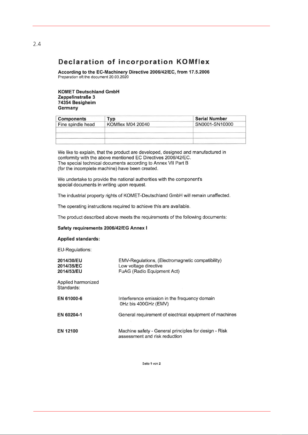
EC Declaration of Conformity .................................................................................................... 3
Radio Approval........................................................................................................................... 5
3 Glossary.............................................................................................................................................. 6
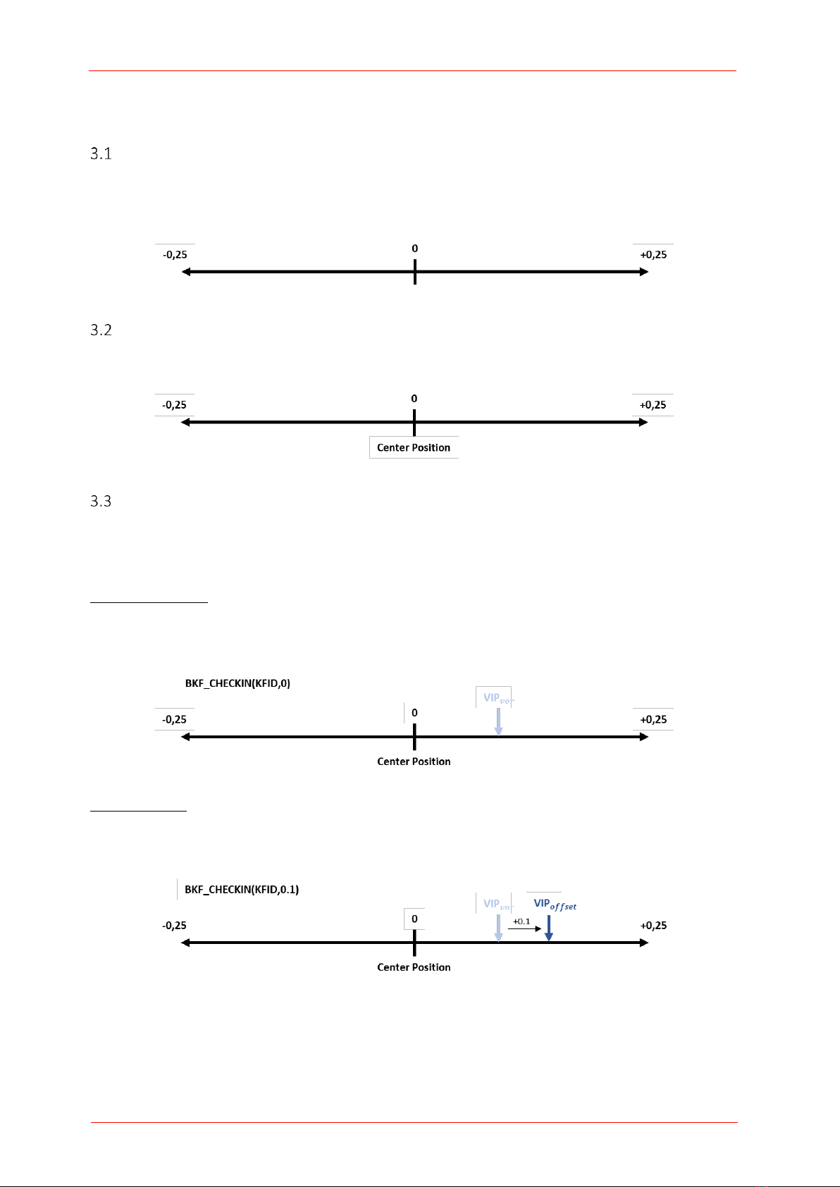
KOMflex adjustment range........................................................................................................ 6
Centre position definition.......................................................................................................... 6
VIP definition.............................................................................................................................. 6
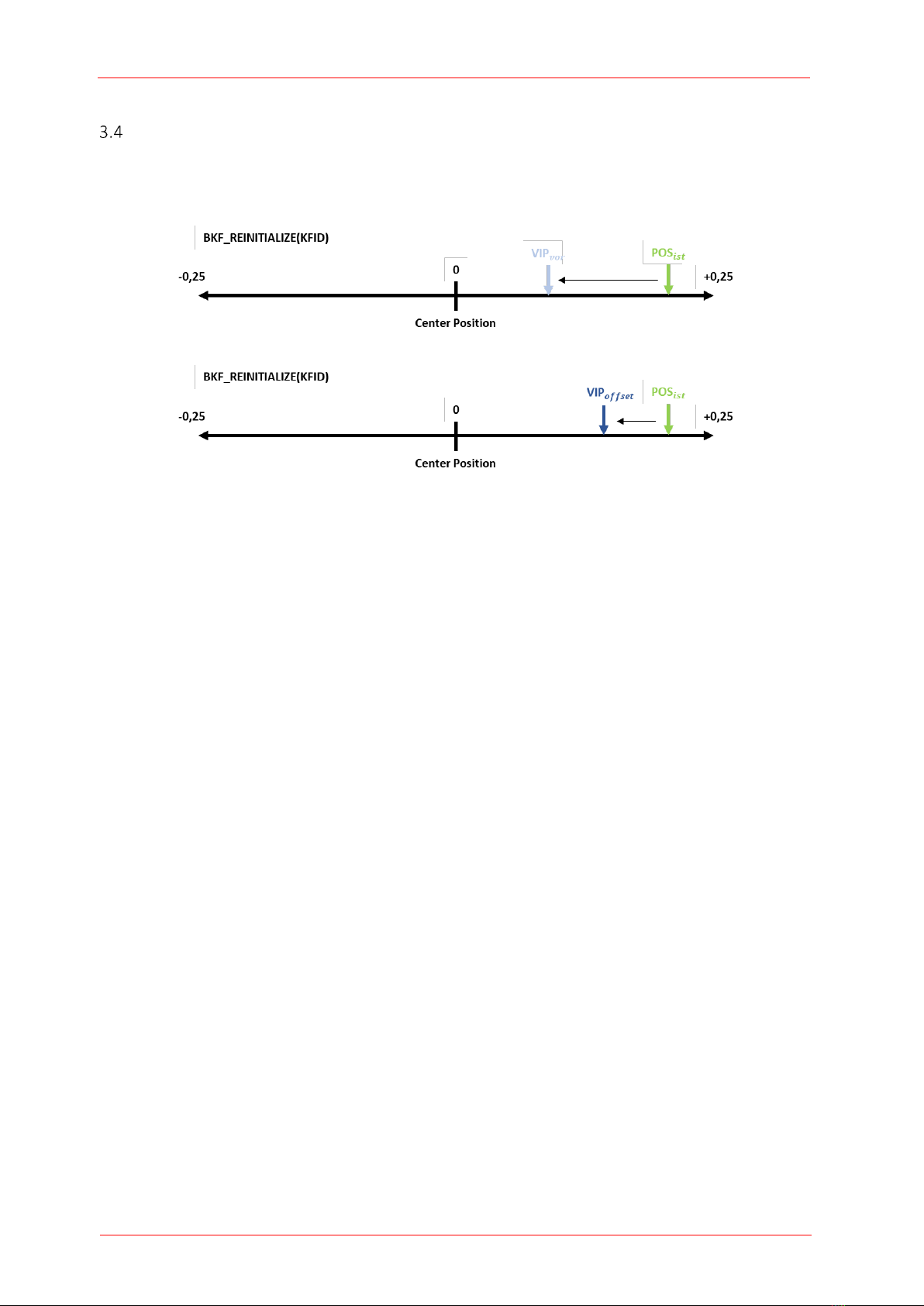
Reinitialisation ........................................................................................................................... 7
4 System overview................................................................................................................................ 8
5 Description of the RC66 wireless receiver......................................................................................... 9
RC66 standby mode................................................................................................................... 9
KOMflex mode ........................................................................................................................... 9
Pairing mode............................................................................................................................ 10
6 Description of the KOMflex precision spindle head ........................................................................ 11
Technical data.......................................................................................................................... 11
KOMflex system description.................................................................................................... 12
Required accessories ............................................................................................................... 12
Description of the KOMflex modes.......................................................................................... 13
6.4.1 Manual adjustment with magnetic pen........................................................................... 13
6.4.2 Automatic adjustment via NC cycle................................................................................. 14
Emergency shutdown .............................................................................................................. 15
If the KOMflex is in an active state, but does not receive any commands from the interface IF20, the
head is deactivated after a timeout of 5 minutes and goes into standby mode................................. 15
Possible scenarios in which an emergency shutdown may occur....................................................... 15
•Switch-off command does not reach the KOMflex, e.g. problems with radio connection ......... 15
•The emergency stop or reset of the NC is activated.................................................................... 15
7 Getting started and tool mounting.................................................................................................. 15
Initial commissioning of the KOMflex...................................................................................... 15
Indicating the basic settings..................................................................................................... 16

KOMflex precision spindle head
Operating instructions V1.1 31.03.2021
cuttingtools.ceratizit.com iii
Classification: Öffentlich
Manually configuring the basic settings .................................................................................. 17
Mounting.................................................................................................................................. 18
7.4.1 Tool mounting.................................................................................................................. 18
7.4.2 Tools with ABS connection............................................................................................... 18
7.4.3 Tool with cylindrical shank............................................................................................... 18
7.4.4 Coolant............................................................................................................................. 19
8 Commissioning the KOMflex............................................................................................................ 20
Presetting equipment .............................................................................................................. 20
Use of the KOMflex on the machine........................................................................................ 22
8.2.1 Overview of the product range........................................................................................ 22
8.2.2 Subprogram for defining the customer program ............................................................ 22
8.2.3 Parameter overview when calling up programs.............................................................. 24
8.2.4 Teaching in the KOMflex.................................................................................................. 25
8.2.5 Correction in automatic mode......................................................................................... 26
8.2.6 Manually switching off..................................................................................................... 27
Reinitialisation of the KOMflex................................................................................................ 27
Extension of the machine with further KOMflex..................................................................... 28
Changing the cutting edge....................................................................................................... 29
Battery replacement................................................................................................................ 30
8.6.1 Changing the battery ....................................................................................................... 30
8.6.2 Disposal of batteries ........................................................................................................ 31
KOMflex errors in machine operation ..................................................................................... 32
BLUM errors in machine operation ......................................................................................... 34
9 KOMflex recycling –Our recycling service....................................................................................... 36
10 List of abbreviations used............................................................................................................ 36

KOMflex precision spindle head
Operating instructions
cuttingtools.ceratizit.com 1
Classification: Öffentlich
1Introduction
Purpose of this document
These operating instructions are designed to familiarise users of the KOMflex precision spindle head
with the following:
•Working principles
•Operation
•Safety information
•Maintenance
Obligations and liability
•An understanding of the fundamental safety information and safety regulations is a basic
prerequisite for safe handling and trouble-free operation of the KOMflex precision spindle head.
•These operating instructions, and in particular the safety information, must be observed by all
persons who work with the KOMflex precision spindle head.
•Furthermore, the accident prevention rules and regulations applicable for the place of use must
be observed.
•The KOMflex precision spindle head is constructed according to the state of the art and
recognised safety rules. Nevertheless, dangers may arise for the user or third parties or the
KOMflex precision spindle head or other items may be damaged during use. The KOMflex
precision spindle head must therefore only be used
ofor its intended use
oin perfect condition in terms of safety.
•If a fault arises which could affect the safety of the KOMflex precision spindle head, it must be
shut down. Please contact the manufacturer.
•Please note that the following causes may affect the operational safety of the KOMflex precision
spindle head as well as the safety of persons working with it:
oImproper use of the KOMflex precision spindle head.
oImproper installation, commissioning, operation and maintenance of the KOMflex
precision spindle head.
oOperation of the KOMflex precision spindle head in a machine with faulty safety devices
or improperly attached or non-functional safety and protection devices.
oNon-compliance with the information in the operating instructions relating to transport,
storage, assembly, commissioning, maintenance and setup of the device.
oUnauthorised modifications to components of the KOMflex precision spindle head.
oInadequate monitoring of device parts which are subject to wear.
oRepairs carried out incorrectly.
oCatastrophes caused by external influences or force majeure.
In isolated cases and under certain circumstances, this may also lead to limitation of liability or
exclusion of liability of the manufacturer, whereby the contractual and statutory rights remain
unaffected by the above.

KOMflex precision spindle head
Operating instructions V1.1 31.03.2021
cuttingtools.ceratizit.com 2
Classification: Öffentlich
2Safety information
Operating personnel
Components must only be operated by trained personnel who are familiar with the working principles,
operation and safety devices of the KOMflex precision spindle head.
Note
Always keep the operating instructions with the KOMflex precision spindle head. The instructions
must always be to hand.
Intended use
The KOMflex precision spindle head is only intended for boring and boring out and over turning. The
KOMflex must only be installed and operated in the machine tools intended for this purpose.
The KOMflex precision spindle head is only to be used as intended for this purpose.
Intended use also includes complying with all the information in these operating instructions. Only
trained and instructed personnel may work with the device.
Improper use
Any other use aside from that listed above is not permitted, as improper use may result in danger
which could cause injury to persons working with or in the vicinity of the KOMflex precision spindle
head or cause damage to the device.

KOMflex precision spindle head
Operating instructions V1.1 31.03.2021
cuttingtools.ceratizit.com 3
Classification: Öffentlich
EC Declaration of Conformity

KOMflex precision spindle head
Operating instructions V1.1 31.03.2021
cuttingtools.ceratizit.com 4
Classification: Öffentlich

KOMflex precision spindle head
Operating instructions V1.1 31.03.2021
cuttingtools.ceratizit.com 5
Classification: Öffentlich
Radio Approval
Japan: R 202LSJ048
“This device has been granted a designation number by Ministry of Internal Affairs and
Communications under „Ordinance concerning Technical Regulations Conformity
Certification etc. of Specified Radio Equipment (特定無線設備の技術基準適合証明等に
関する規則)“ Article 2-1-19.
USA: FCC ID: 2A2B9KOMFLEX FCC Part 15
This equipment has been tested and found to comply with the limits for a Class B digital
device, pursuant to part 15 of the FCC Rules. These limits are designed to provide
reasonable protection against harmful interference in a residential installation. This
equipment generates, uses and can radiate radio frequency energy and, if not installed
and used in accordance with the instructions, may cause harmful interference to radio
communications. However, there is no guarantee that interference will not occur in a
particular installation. If this equipment does cause harmful interference to radio or
television reception, which can be determined by turning the equipment off and on, the
user is encouraged to try to correct the interference by one or more of the following
measures:
—Reorient or relocate the receiving antenna.
—Increase the separation between the equipment and receiver.
—Connect the equipment into an outlet on a circuit different from that to which the
receiver is connected.
—Consult the dealer or an experienced radio/TV technician for help.
Changes or modifications made to this equipment not expressly approved by CERATIZIT
USA, Inc. may void the FCC authorization to operate this equipment. This device complies
with part 15 of the FCC Rules. Operation is subject to the following two conditions:(1) This
device may not cause harmful interference, and (2) this device must accept any
interference received, including interference that may cause undesired operation.
Canada: IC:27454-KOMFLEX
This device contains licence-exempt transmitter(s)/receiver(s) that comply with
Innovation, Science and Economic Development Canada’s licence-exempt RSS(s).
Operation is subject to the following two conditions: (1) this device may not cause
interference, and (2) this device must accept any interference, including interference that
may cause undesired operation of the device. This device and its antenna(s) must not be
co-located or operating in conjunction with any other antenna or transmitter. This
equipment complies with IC Canada RF radiation exposure limits set forth for an
uncontrolled environment as per RSS-102 Issue 4.
L’émetteur/récepteur exempt de licence contenu dans le présent appareil est conforme
aux CNR d’Innovation, Sciences et Développement économique Canada applicables aux
appareils radio exempts de licence. L’exploitation est autorisée aux deux conditions
suivantes (1) L’appareil ne doit pas produire de brouillage, et (2) L’appareil doit accepter
tout brouillage radioélectrique subi, même si le brouillage est susceptible d’en
compromettre le fonctionnement.

KOMflex precision spindle head
Operating instructions V1.1 31.03.2021
cuttingtools.ceratizit.com 6
Classification: Öffentlich
3Glossary
KOMflex adjustment range
The KOMflex can be adjusted between -0.25 mm and +0.25 mm in relation to the central position of
the slide.
Centre position definition
The centre position (CP) is the central position of the slide (zero point).
VIP definition
The VIP is a defined position in the KOMflex adjustment range which serves as a reference point, for
example during the trial cut or for safe changeover of the indexable insert.
VIP without offset:
The VIP must be set manually by the user, for example on the presetting equipment, before automatic
operation. The VIP can be set within the entire adjustment range of the KOMflex.
VIP with offset:
It is possible to subsequently overwrite the set VIP position by carrying out teach-in (initialisation) of the
head again via the OFFSET input parameter in the BKF_CHECKIN NC program and thereby set it again.
The VIP preset by the user is then used by the BKF_CHECKIN NC program. (See section 8.2.4)

KOMflex precision spindle head
Operating instructions V1.1 31.03.2021
cuttingtools.ceratizit.com 7
Classification: Öffentlich
Reinitialisation
During reinitialisation, the KOMflex precision spindle head is reverted to its initial state. This means that
the KOMflex travels to the VIP and the radius wear in the tool table is reset to 0. (See section 8.3)

KOMflex precision spindle head
Operating instructions V1.1 31.03.2021
cuttingtools.ceratizit.com 8
Classification: Öffentlich
4System overview
The KOMET KOMflex compensation system consists of the following components:
•KOMET KOMflex with BLUM wireless unit
•BLUM RC66 receiver
•BLUM IF20 interface
•BLUM EM3x extension module
•BLUM software
•Any measuring unit, e.g. measuring probe
The automatic KOMflex compensation system enables process-secure boring of holes and pins on a
machine tool. The finished hole is measured with any measuring unit and compared to the target
dimension. The precision spindle head then automatically corrects the set value deviation. To do so the
dimension to be adjusted is transferred from the NC to the IF20 Interface via Ethernet or field bus. The
value is then wirelessly transferred to the KOMET KOMflex.
Snap-on tools
Ø 1 –120 mm
KOMflex
precision
spindle head
BLUM wireless machine equipment
+ any measuring unit
BLUM
IF20 interface
BLUM
RC66 wireless
receiver
Machine compartment
Control cabinet
KOMET
KOMflex
BLUM
EM3x module
Measuring
probe

KOMflex precision spindle head
Operating instructions V1.1 31.03.2021
cuttingtools.ceratizit.com 9
Classification: Öffentlich
5Description of the RC66 wireless receiver
The RC66 is a compact wireless receiver with BRC technology which is suitable for all Blum measuring
devices and the KOMflex with wireless transmission. It enables wireless communication between the
measuring devices/the precision spindle head and the NC control. Data is transferred to the NC control
via the IF20 interface.
The meaning of the RC66 display indicators is explained below, focusing on the KOMflex-specific
operating modes.
RC66 standby mode
Only the status LED (1a) is active in standby mode. This will light up red, green and blue alternately.
The mode is set via the SET_STBY command.
t
KOMflex mode
In KOMflex mode, the MODE LED (1a) and the RX LED (1d) light up steady green and the BATTERY LED
(1b) is inactive. The display indicators can be found in the following table.
This mode can be activated with the SET_KOMFLEX_MODE command.
1e: TX:
1d: RX:
1b: BATTERY:
1c: STATUS:
1a: MODE:
GN
OG
GN
RD
GN
GN
OG
RD
Data transfer
KOMflex activation command
Data transfer
Incorrect data received
Unused/inactive
KOMflex mode
Connected to KOMflex
KOMflex activation attempt
No connection to KOMflex
(activation failed)

KOMflex precision spindle head
Operating instructions V1.1 31.03.2021
cuttingtools.ceratizit.com 10
Classification: Öffentlich
Pairing mode
The MODE LED (1a) flashes white continuously in pairing mode. The TX and RX LED (1d, 1e) indicate that
data is being transferred.
Once a KOMflex has been successfully taught-in, the BATTERY and the STATUS LED (1b, 1c) flash green.
If pairing fails, due to timeout or a problem with the data transfer or an incorrect device type, for
example, then the BATTERY and STATUS LED (1b, 1c) flash red.
The mode is set via the SET_KOMFLEX_MODE command.
1d: RX:
1b: BATTERY:
GN
GN
RD
Data transfer
Pairing successful
Pairing failed
1e: TX:
GN
Data transfer
1c: STATUS:
GN
RD
Pairing successful
Pairing failed
1a: MODE:
Pairing mode active
WH

KOMflex precision spindle head
Operating instructions V1.1 31.03.2021
cuttingtools.ceratizit.com 11
Classification: Öffentlich
6Description of the KOMflex precision spindle head
The automatic precision spindle head communicates with the BLUM RC66 wireless interface and forms
a closed-loop operation (process, measure, correct, process) in conjunction with any measuring unit.
Therefore, the KOMflex enables automatic diameter correction for precision holes.
Technical data
Adjustment accuracy
1 µm in radius
Adjustment range
± 0.25 mm
Boring range
Dia. 1 - 120 mm
Max. RPM
8000 RPM
Max. transmittable torque
16 Nm
Max. coolant pressure
30 bar
Height
100 mm
Outer diameter
63 mm
Weight of head without tool
1.536 kg
Operating temperature
+10 °C to +40 °C
Storage temperature
-20 °C to +60 °C
Interface
ABS 50
Protection class
IP67
Lithium thionyl chloride battery
2x AA Saft LS14500
Hight = 100 mm
ABS 32 /
Ø 16 mm /
Teeth

KOMflex precision spindle head
Operating instructions V1.1 31.03.2021
cuttingtools.ceratizit.com 12
Classification: Öffentlich
KOMflex system description
Required accessories
To operate the KOMflex in manual mode and to teach-in the precision spindle head on the machine
tool, a magnetic pen or comparable magnet is required.
①
ABS 50 adapter
②
Combined tool interface
ABS 32 / dia. 16 mm / teeth
③
Slide
④
Inner and outer coolant supply
⑤
Battery compartment WAF2.5
⑥
ABS32 clamping screw WAF4 /
9-11 Nm
⑦
Battery polarity
⑧
MODE hall sensor
⑨
SET hall sensor
⑩
LED status (3x 120° = 360°)
⑪
Balance compensation
Magnetic pen
Magnet

KOMflex precision spindle head
Operating instructions V1.1 31.03.2021
cuttingtools.ceratizit.com 13
Classification: Öffentlich
Description of the KOMflex modes
The KOMflex can be operated in manual or automatic mode. Both modes Manual adjustment with
magnetic pen and Automatic adjustment via NC cycle are covered in more detail below.
6.4.1 Manual adjustment with magnetic pen
To operate the KOMflex in manual mode, for example on the presetting equipment, the precision
spindle head must be in standby mode (all KOMflex LEDs off). The user can then activate manual mode
with a prolonged touch of the "MODE" sensor with the magnetic pen. When the magnetic pen is
removed from the sensor and the LEDs change from yellow to orange, "Manual adjustment" mode is
active.
General information
Brief touch of the button:
20 ms < t < 1.5 s
To the + stop: LED flashing
Long touch of the button:
1.5 s < t < 5 s
To the + stop: LED flashing
Switch on
Manual travel
ready
Travel by 5 µm
Travel by 1 µm
Brief press
of MODE
LED
Brief press
of SET
LED
Long press
of MODE
Approach centre
position (CP)
Long
press of
SET
LED
Long press
of MODE
LED
IDLE
Manual travel
auto
SET
MODE
LED : Travel in plus direction
LED : Travel in minus direction
Long press
of MODE
Switch off
All LEDs off
>20 s no
action
MODE
"button
"
LED
SET
"button
"
auto
In event of error
LED
auto
auto
auto
auto
Change direction
of travel
LED or LED
LED changes to LED
GN
BU

KOMflex precision spindle head
Operating instructions V1.1 31.03.2021
cuttingtools.ceratizit.com 14
Classification: Öffentlich
6.4.2 Automatic adjustment via NC cycle
Successful teach-in of the precision spindle head is the prerequisite for automatic operation of the
KOMflex, see section 8.2.4. In standby mode (all KOMflex LEDs off), "Automatic adjustment" mode can
be activated via the computerised numerical control (CNC). In this state, the precision spindle head
indicates the key statuses via flashing LEDs. An overview of the statuses is given below.
Application scenarios
KOMflex active and ready for adjustment, waiting for commands
t
KOMflex active, "ready" not yet received from the KOMET module
t
KOMflex active, timeout (tKOMflexReadyMax), no "Ready" received from the KOMET module
t
Battery status
KOMflex inactive, "low" battery status (CRITICAL). KOMET module does not carry out any actions
t
KOMflex inactive, "empty" battery status (BAD)
t

KOMflex precision spindle head
Operating instructions V1.1 31.03.2021
cuttingtools.ceratizit.com 15
Classification: Öffentlich
Emergency shutdown
If the KOMflex is in an active state, but does not receive any commands from the interface IF20, the
head is deactivated after a timeout of 5 minutes and goes into standby mode.
Possible scenarios in which an emergency shutdown may occur
•Switch-off command does not reach the KOMflex, e.g. problems with radio connection
•The emergency stop or reset of the NC is activated.
7Getting started and tool mounting
Initial commissioning of the KOMflex
The insulation pad located in the battery compartment must be removed for initial commissioning. Then
the precision spindle head can be put into operation.
Note
Note the correct position of the seal in the battery compartment. Keep the battery compartment
completely clean and dry. Lightly grease the sealing surface of the lid before inserting the lid.
1. Unscrew the screws on the battery compartment lid.
2. Pull both screws out and remove the battery lid.
3. Remove the insulation pad from the battery compartment.
4. Check whether the seal is correctly inserted: small, even distance of the sealing lip to the wall.
5. Fit the battery compartment lid so it is straight and secure it (Md = 0.7 Nm).
6. When screwing the battery lid on, ensure it is positioned correctly and that the O ring is in perfect
condition. If the O ring is damaged, replace it.
Open battery compartment
during initial commissioning
Remove insulation pad
Screw the battery
compartment lid back
into place
Pay attention to the battery
polarity!
(See housing signature)
Open battery compartment
during initial commissioning
Remove insulation pad Screw the battery compartment
lid back into place

KOMflex precision spindle head
Operating instructions V1.1 31.03.2021
cuttingtools.ceratizit.com 16
Classification: Öffentlich
Indicating the basic settings
Once the insulation pad has been removed/the batteries have been inserted, the basic settings are
indicated. The magnetic pen is not needed for this. Once the basic settings have been indicated, the
precision spindle head goes into standby mode.
Head active
IDLE
MODE
SET
Characteristics
Transmission mode
(3 x MODE - SET)
Normal*
Robust
• Standard setting
• Ambient conditions with radio interference
• High chip load
ON time
(3 x MODE - SET)
Fast
Normal*
Slow
• Fast ON time
• Setting reduces the battery life
• Normal ON time
• Standard setting
• Slow ON time
• Setting increases the battery life
Device type
(3 x MODE - SET)
Standard*
EcoMode
TWIN A
TWIN B
• Activation readinessa
• Setting reduces the battery life
• Activation readinessb
• Setting increases the battery life
Battery
(3 x MODE - SET)
O.K.
Low
Standby
* Standard settings
aThe KOMflex is always ready for re-activation in standby mode.
b If the KOMflex:
-Is outside the reception range of the wireless receiver, the system goes into EcoMode.
-Is within the reception range, it is always ready for re-activation.
GN
RD
RD
GN
BU
RD
GN
GN
BU
RD
OG
OG
WH
BU
GN
RD

KOMflex precision spindle head
Operating instructions V1.1 31.03.2021
cuttingtools.ceratizit.com 17
Classification: Öffentlich
Manually configuring the basic settings
The basic settings can be changed in this mode.
Note
The magnetic pen is needed to operate the KOMflex in this section.
1. Remove the batteries.
2. After 30 seconds, re-insert the batteries in the battery compartment. Pay attention to the
battery polarity. Refit the battery compartment lid.
3. The basic settings are indicated (indication phase).
4. During the indication phase, switch to programming mode:
Hold the magnetic pen on the MODE text for 5 seconds until the status LED changes from
green to violet.
5. In programming mode, you can perform two actions:
•Change settings (SET):
Hold the magnetic pen on the SET text.
•Switch to another menu item (MODE)
Hold the magnetic pen on the MODE text. The status LED briefly flashes violet to confirm
the menu change has been detected.
6. After the last menu item, the basic settings are repeated (3 x MODE -SET) and saved*. During
the indication phase, you can switch back to programming mode.
7. Once the basic settings have been indicated, the precision spindle head goes into standby
mode.
*The set basic settings are retained after the battery is changed.
Pay attention to the battery
polarity!
(See housing signature)
Insert the batteries into the
battery compartment
Indication phase for the basic
settings
Switch to programming mode
Table of contents