Cervélo P Series User manual

2020 P-SERIES RETAILER ASSEMBLY MANUAL

2
This manual is intended to guide ocial Cervélo retailers, through the assembly and adjustment of the
Cervélo P-Series. This manual outlines the process and procedure associated with the installation of
Cervélo components, as well as the routing of shifting and braking control lines only. Proprietary parts
referenced in this manual are available only through Cervélo Cycles Inc. directly.
Failure to use the specied parts and follow these assembly instructions may result in loss of control
while riding, leading to serious injury. This manual is not intended to replace the assembly and service
instruction provided by third-party component manufactures, and assumes that the assembler is a
trained, professional bicycle mechanic. See https://www.probma.org/
INTRODUCTION
Important Information.....................................2
Required of Tools & Supplies..............................3
P-Series Assembly Overview................................4
PRE-ASSEMBLY
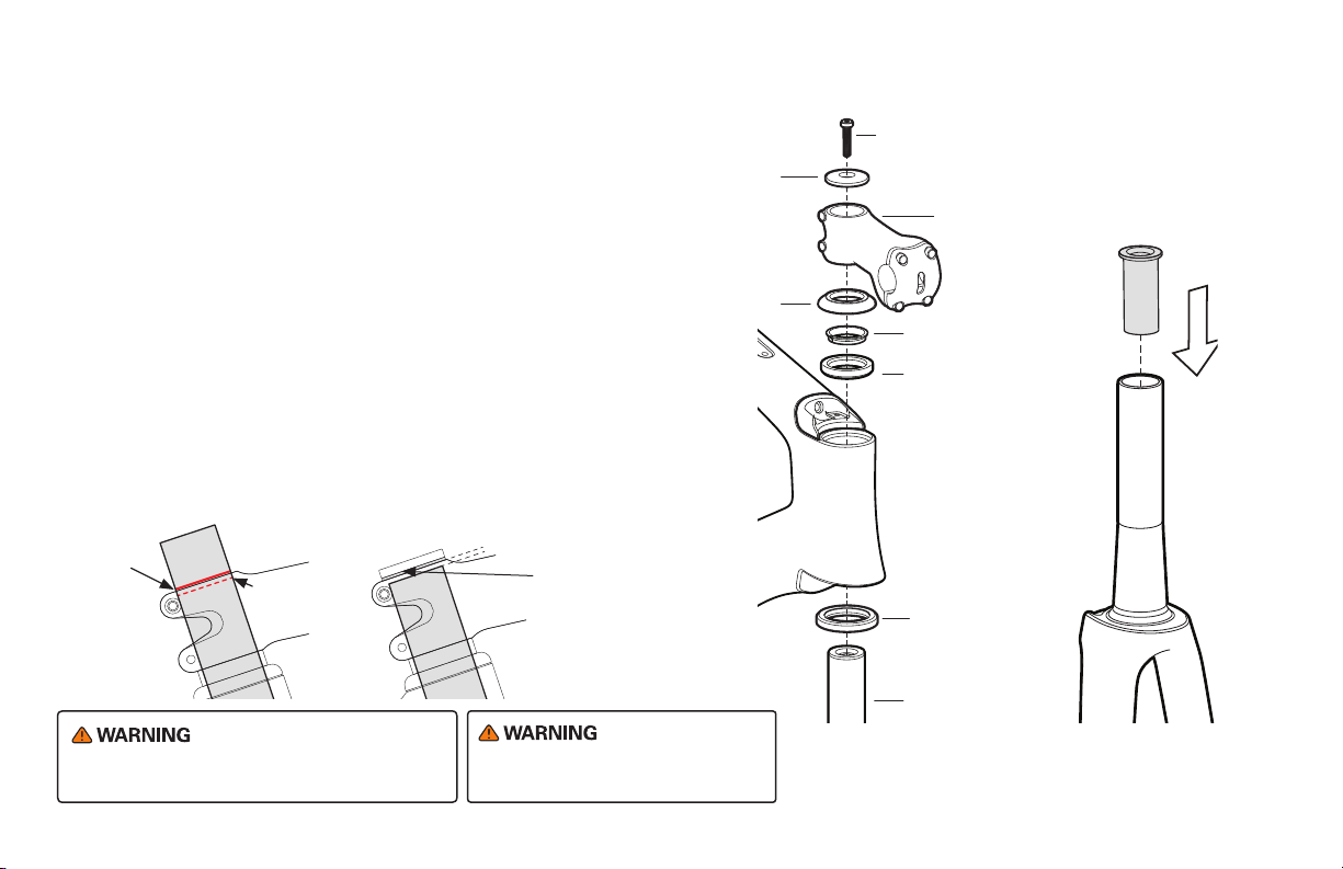
Frame and Fork Preparation..............................5-6
Fork Installation.........................................7
ASSEMBLING THE P-SERIES
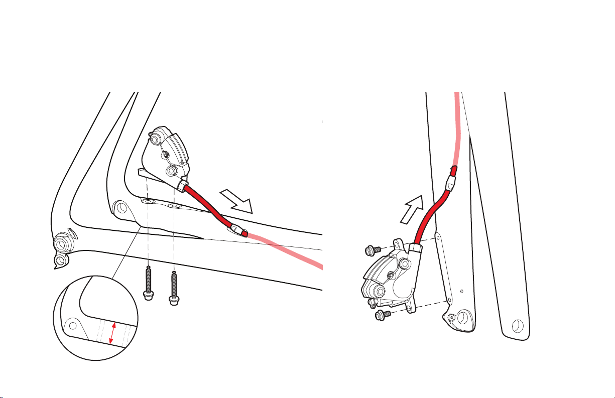
Brake Housing Routing...................................8-9
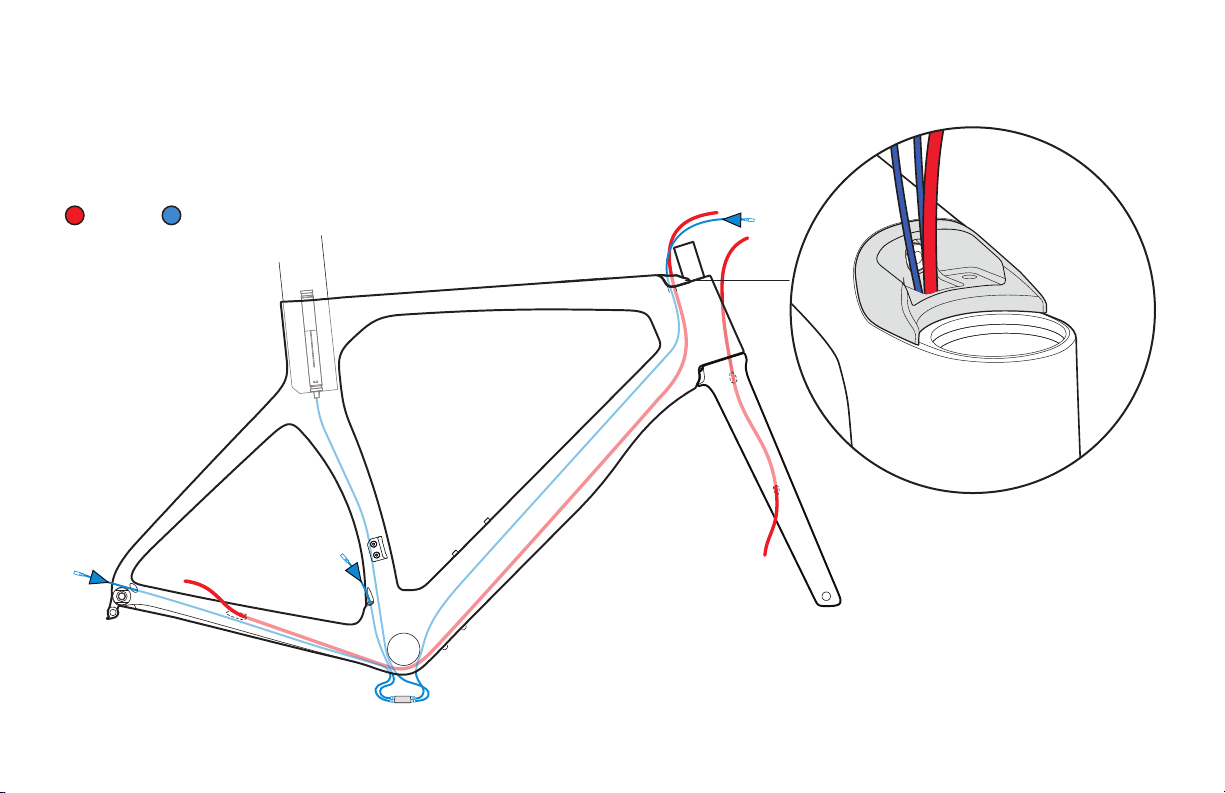
Electric Cable Routing................................10-11
Mechanical Cable Routing..............................12-13
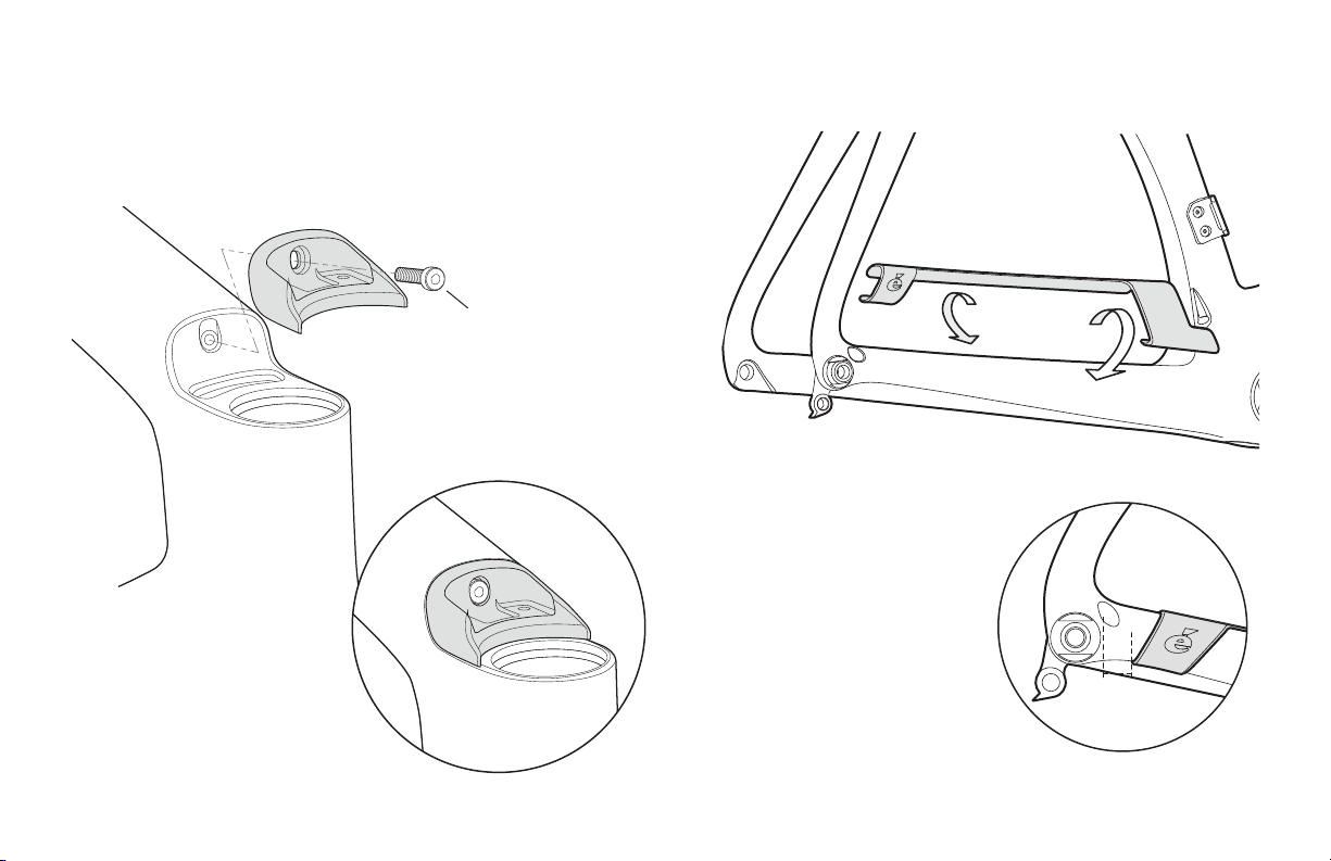
Top Tube Cable/Hose Guide Installation...................14
Top Tube SmartPak Installation...........................15
Seatpost Assembly ....................................16-17
Seatpost Cutting Instructions............................18
Seatpost Di2 Battery Installation........................19
Tire Clearance...........................................20
Aero Through-Axle Wheel Installation..................21-22
OTHER
Compatible Parts and Hardware............................23
CER-PSERIES-V1.0 - 2019-06-07
TABLE OF CONTENTS
IMPORTANT INFORMATION
NOTE: Cervélo strongly recommends that
all assembly and adjustment procedures
be performed by an authorized Cervélo
retailer. If you are a Cervélo P-Series
consumer/purchaser reading this manual
we suggest that before attempting to
undertake any of the procedures in this
manual that you consult your authorized
Cervélo retailer, or visit us at
www.cervelo.com/support

3
NOTE: This manual was developed to
compliment the Cervélo General User
Manual, and is intended as a supplement
to the assembly and installation
instructions supplied by the component
manufacturers (provided with this
bicycle).
NOTE: All non-proprietary components are
available from your local distributor.
LIST OF TOOLS & SUPPLIES
This manual outlines a number of procedures
for making optional adjustments to the P-Series
which dier from the way the bicycle is originally
sold by Cervélo.The following tools and parts
listed are required for these adjustments. These
parts are not available for consumer purchase
and are only available for purchase by Cervélo
retailers. Cervélo strongly recommends that
all assembly and adjustment procedures be
performed by an authorized Cervélo retailer.
Tools
Bicycle workstand (types which
secure bike by the seatpost, or
pro-type stand with fork mount)
Torque wrench(es) with 2.5Nm to
15Nm range and adaptors:
Allen (Hex) head inserts:
2mm, 2.5mm, 3mm, 4mm, 5mm,
6mm, 8mm, 10mm
Open ended wrenches:
7mm, 8mm, 10mm, 17mm
Cable cutters
Pliers
Tools
Phillips-head screwdriver
Slot-head screwdriver
Pedal wrench
Brake rotor lockring tools
Hydraulic bleed kit
Di2 wire tool – Shimano
Good quality bicycle grease

4
Dropout Shift Cable
Stop (Mechanical)
CBS-DRPOUT
4
P-SERIES ASSEMBLY OVERVIEW
Toptube Brake
Hose Shift
Housing Guide
HBP-GU02-CVR
Fork Insert
Threaded w/Bolts
QRI-THD
5
8
15
9
16
29
18
3
SP23 Seatpost
Assembly
SP-SP23
MT-WB-SP
Derailleur Hanger
w/Mounting Nut
DRH-WMN112
2Seatpost Clamp
SPC-0E0P
Front Derailleur
Mount w/Bolts
FDM-OEO
Brake Hose Guide x3
CBG-DBH
Chainstay Protector
PRO-CS-P
Bottle Boss Cover Plate
CVR-WB
BB Cable Guide/Cover
BBG-0E0
Rear Aero
Thru Axle
QRA-AERO-R
Front Aero
Thru Axle
QRA-AERO-F
Dropout Open
Grommet(Electronic)
GR-DRPOUT-GUIDE
10
Seat Tube Open
Grommet(Electronic)
GR-BEC-OPEN
12
23 Seatpost Battery
Mount
MT-BINT-SP
Smartpak400 w/Bolts
SB-SB03-TT
Aero Bottle w/ Cage
WB-WB01
25 13

FRAME & FORK PREPARATION
Lightly grease Rear Derailleur Hanger Fixing
Nut and install Rear Derailleur Hanger (DRH-
WMN112) nger tight. Final tightening will be
done after rear wheel installation.
Lightly grease supplied M4 xing screw, and
install the Front Fork Axle Insert (QRI-THD) to
the fork. Torque to 3Nm.
Ensure Front Derailleur Mount xing
screws are torqued to 3Nm.
1. Apply carbon assembly compound to both
frame and seatpost.
2. Insert Seatpost Clamp (SPC-0E0P5) fully into
frame so it is fully ush with the top tube.
3. Adjust height and torque to 8Nm maximum.
Do not nal tighten rear derailleur hanger
assembly without rear wheel installed. Doing
so will result in a misaligned derailleur and
poor shifting.
Hold the frame
using a secured
seatpost only.
Clamping the top tube
can damage the frame
and void your warranty.
5

Lightly grease supplied M4
xing screw, and install the
GU02 Base Piece to the frame.
Torque to 1-2Nm.
6
FRAME & FORK PREPARATION
15mm
Note: Install GU02 Base piece onto frame prior
to installing fork to ensure ease of access to the
xing srew.
Clean the chainstay using
isopropyl alcohol. Install the
Chainstay Guard by removing
adhesive backing, and xing
the guard to the frame. The
bottom rearward edge should
be approximately 15mm from
the edge of the Rear Derailleur
Hanger Fixing Nut.
M4 x 16mm
Fixing Screw

7
Your Cervélo frame & fork have been designed to work
together. Do not attempt to install an alternative fork.
1. Apply grease to the bearing seats, and Install the upper & lower headset
bearings into the head tube.
2. Fit the fork provided with your frame into the head tube with the complete
headset, required spacers, and the stem.
3. Tighten the Top Cap bolt to take slop out of system and ensure the assembly
is fully seated (1-2Nm). Mark the steerer tube at the top of the stem.
4. Remove fork and clearly mark the fork steerer tube at a point 4mm below the
rst mark. Take care to verify that this measurement is correct as this denes
the cut line for the steerer tube.
5. Lightly grease supplied M4 xing screws, and install the Fork Dual Oset Axle
Inserts to the fork. Tighten to 3Nm.
1. Maximum of 5Nm.
2. As a nal check ensure that the fork rotates freely in the head tube without
any play or binding. If any problem is detected, loosen the bolts and
perform steps 7) to 8) again.
FORK INSTALLATION
Install preload
insert in fork.
Torque to 8Nm
NOTE: This diagram is for assembly reference
only. During complete assembly, hoses and
control cables will be present.
Preload Fixing
Screw M6 x 30mm
Stem Preload
Top Cap
1 1/8" Upper
Bearing
1 3/8" Lower
Bearing
Compression Ring
Stem
Fork Steerer
Bearing Top
Cap
Max.
4mm
A 2.5mm
spacer under
the Stem Cap
is advised
1st
Mark
2nd Mark
/Final Cut
Avoid breathing the dust created during
cutting carbon composite materials.

8
It is recommended that the rear hydraulic brake hose or brake cable housing is installed rst. These routing
illustrations are intended as a supplement to the manufacturer’s installation instructions only. For both
hydraulic and mechanical disc brakes, please refer to the component manufacturer’s service center
or website for further information.
BRAKE HOUSING ROUTING
Route rear brake hose from
chainstay through from Top
Tube Cable/Hose Port.
Route brake hose
from bottom of
fork up and out
through the upper
fork exit.

Chainstay
height: 30mm
9
Route hydraulic brake hose or mechanical brake housing through the frame and fork with the Disc
Hose Bushings (CBG-DBH). Install and adjust calipers as per manufacturer’s instructions.
BRAKE HOUSING ROUTING

10
It is recommended that electric cabling and junction points be installed after the brake
hose has been installed. These routing illustrations are intended as a supplement
to the manufacturer’s installation instructions only. Please refer to the component
manufacturer’s service center or website for further information.
ELECTRIC CABLE ROUTING
Brake E-Wire
Route the Di2 E-Wire from
Top Tube Cable/Hose Port
out through Bottom Bracket
Cable Port.
See page 19 for seatpost
battery installation
instruction

11
With all wires inside, cap the
Bottom Bracket Cable Port with the
BB Cable Guide/Cover (BBG-0E0).
Install the Rear Derailleur Wire Guide (GR-DRPOUT-GUIDE).
For wireless shifting
systems install the Rear
Derailleur Blanking Plug
(GR-DRPOUT-CLOSED).
ELECTRIC CABLE INSTALLATION

12
It is recommended that front and rear derailleur cables be installed after the brake
hose has been installed. These routing illustrations are intended as a supplement
to the manufacturer’s installation instructions only. Please refer to the component
manufacturer’s service center or website for further information.
MECHANICAL CABLE ROUTING
Ensure that the shifter housing
is not twisted together. Add
ferrules to the bottom bracket
end of the housing.
Brake Rear Shifter Front Shifter
Route shifter housing from
Top Tube Cable/Hose Port
out through Bottom Bracket
Cable Port.

13
The front cable travels across the non-drive side slot, and in
the direction of the seat tube. The rear cable travels along
the drive side slot, and along the chainstay. When complete,
x the BB Cable Guide/Cover (BBG-0E0) into place.
Install Rear Derailleur Press-In Cable Stop (CBS-DRPOUT).
As per manufacturer’s instructions, install rear derailleur on rear
derailleur hanger, cut appropriate housing length, and attach cable.
MECHANICAL CABLE INSTALLATION
Ensure ferrules
are used to cap
shifter housing
at BB Cable
Guide/Cover.

14
TOP TUBE CABLE/HOSE GUIDE INSTALLATION
M4 x 20mm
Torque to 1Nm
GU02 Stemcover
Rubber part
M4 Washer
After Cabling is complete, insert GU02 Guide Left and Right
parts to secure hoses in place. Once in order, install the
GU02 Stem cover Rubber part with washers in place. Torque
to 1Nm.
Installed
Position

15
TOP TUBE SMARTPAK INSTALLATION
M5 x 18mm
Torque to 1-2Nm
M5 Washer
SmartPak
Top Tube Storage
(SB-SB03-TT)
Ensure tabs are in place
and sides held inward
during installation.

16
M5 x 16mm
Fixing Screws
SEATPOST ASSEMBLY
Slide the lightly greased seatpost
bottle cage mount slug into the
seatpost.
If not using the bottle cage mount, use the
alternate seatpost slug (SPS-SP2123).
1. Install saddle mount to slug using
lightly greased M5 xing screws.
2. Torque to 6-7Nm.
3. Install lightly greased M6 Rail
Binder Bolt, and install saddle.
4. Torque to 12Nm.
5. Determine desired angle, and attach
water bottle mount to seatpost slug
with M5 xing screw.
6. Torque to 4Nm.
Rail Binder Bolt
M6 x 55mm
Seatpost Water Bottle
Mount(MT-WB-SP)

17
SEATPOST ASSEMBLY
UCI P5 Seatpost
(SP-CER-UCI-ACB)
SP23 Seatpost
(SP-SP23)
Attach water bottle cage using lightly greased
M5 x 8mm xing screws. Torque to 2-3Nm.

Cut Line
1cm
1cm
18
1. Taking care to maintain the minimum required seatpost insertion of 6.5cm and
maximum of 8.5cm, carefully measure and use a light coloured grease pencil
to accurately mark the cut-o location on the seatpost.
2. Insert the P Series Seatpost in the Park Tool SG-7.2 Saw Guide (or equivalent)
so that the cut-o line can be seen clearly through the blade guide in the tool.
3. Using a blade designed specically for cutting carbon composite materials (or
a ne tooth blade with greater than 32 teeth per inch); proceed with cutting the
Seatpost (as per Park Tool’s instructions).
4. Use ne grit sandpaper to carefully remove any fraying or burring from the cut
end. Reposition clamp approximately 10cm from the cut end.
5. With a grease pencil, mark a point 1cm from the cut end on the trailing edge of
the Seatpost, and another 1cm from the back, on the bottom edge. Draw a line
connecting them, forming a 45 degree guideline.
6. Placing the blade of your saw on the grease pencil mark, very carefully
proceed to cut, resulting in a 45 degree chamfer being cut onto the trailing
edge of the Seatpost.
7. Carefully sand the end and after applying carbon assembly compound,
return to the frame.
Note: It is essential that all Cervélo Aero Seatposts, have a 45
degree chamfer cut on the rear trailing edge of the post. If trimming
is required after tting, the following method is recommended.
SEATPOST CUTTING INSTRUCTIONS
If trimming is required, nal length should allow for a minimum
6.5cm of seatpost remaining in the frame. Failure to meet this
requirement, may result in damage to the frame not covered by
warranty policy, or serious injury to rider.

19
SEATPOST DI2 BATTERY INSTALLATION
Press the Di2 battery into the Seatpost Battery
Mount (MT-BINT-SP) and attach the E-Wire
according to the manufacturers instructions.
Insert the assembled battery and battery
mount into the seatpost.
P Series Seatpost
Battery Mount
(MT-BINT-SP)

20
TIRE CLEARANCE
Your Cervélo bicycle complies with the ISO 4210-2:4.10.2 standard for tire clearance. In order to comply with these safety standards and
maintain your Limited Lifetime Warranty, a minimum of 4mm of clearance must remain between the tire and any frame element. Due to
the growing complexity of tire and rim interfaces, Cervélo recommends identifying the available space before choosing a tire.
1. Measure the space between the chainstays at
the bottom bracket junction.
2. Measure the space between the seatstays at
the top of the tire.
3. Using the smallest of those two numbers,
subtract 8mm (4mm per side) to determine
the remaining space.
4. With the tire installed and fully inated on
your wheel, measure the tire width to ensure
that it ts.
Tire
Dimension
Frame
Clearance
Contact between the tire and the frame or
fork may result in a loss of control while
riding and potentially serious injury. Failure to
follow these guidelines may result in damage
to the frame not covered by Cervélo Limited
Lifetime Warranty.
Table of contents
Other Cervélo Bicycle Accessories manuals