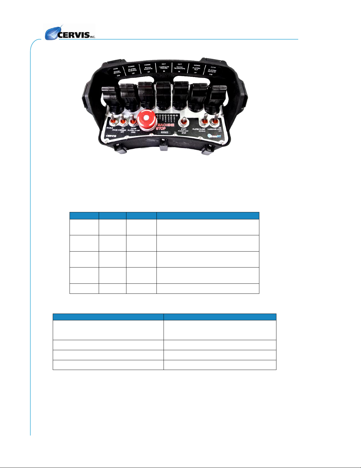
SmaRT Console Box Remote
Cervis, Inc. Safety Precautions
✓Read and follow all instructions.
✓Failure to abide by Safety Precautions may cause equipment failure, loss of authority
to operate the equipment, and personal injury.
✓Use and maintain proper wiring. Follow equipment manufacturer instructions.
Improper, loose, and frayed wiring can cause system failure, equipment damage, and
intermittent operation.
✓Changes or modifications made to equipment not expressly approved by the
manufacturer will void the warranty.
✓Equipment owner/operators must abide by all applicable Federal, State, and Local
laws concerning proper equipment installation and operation. Failure to comply could
result in penalties and could void user authority to operate the equipment.
✓Make sure that the machinery and surrounding area is clear before operating. Do not
activate the remote control system until certain that it is safe to do so.
✓Turn off the handheld remote and remove power from the base unit before attempting
any maintenance. This will prevent accidental operation of the controlled machinery.
✓Remove power from the base unit either by detaching the 12-pin cables from the
enclosure or by removing the source power from the base unit circuit.
✓Use a damp cloth to keep units clean. Remove mud, concrete, dirt, etc. after use to
prevent obstructing or clogging the buttons, levers, joysticks, wiring, and switches.
✓Do not allow liquid to enter the handheld or base unit enclosures. Do not use high-
pressure equipment to clean the handheld remote or base unit.
✓Disconnect the radio base unit before welding on the machine. Failure to disconnect
the base unit may cause destruction of or damage to the base unit.
✓Operate and store units only within the specified operation and storage temperatures
defined in this document’s specifications.
✓Keep high-energy radio frequency (RF) devices away from handheld remotes.
Activating high-power communication radios, for instance, in close proximity to
handheld remotes can cause interference and “false” circuit activation.
✓Do not key two-way radios while using the console box remote.
✓
Note: A SmaRT handheld remote’s operating frequency is in either the 2.4 GHz or 900 MHz
range. The first number in the system or device name indicates the operating frequency. For
instance, a SmaRT CB-xH (console box) handheld remote in this document may either be
CB-2H12LV or CB-9H12JS (or some variation of levers [LV] and joysticks [JS]), where “2”
indicates 2.4 GHz and “9”indicates 900 MHz operating frequency. As such, references to the
handheld remote, base unit, or system in this manual may use “x”rather than “2”or “9”in the
name to indicate the operating frequency.