Table of Contents
Table of Contents.......................................................................................................................... i
List of Figures ............................................................................................................................... i
List of Tables................................................................................................................................ ii
Cervis, Inc. Safety Precautions ................................................................................................. iii
1.0 Warrior Locomotive Remote Control (LRC) Console Box Transmitter Introduction.... 1
1.1 Features............................................................................................................................. 1
2.0 Warrior LRC Transmitters................................................................................................... 2
2.1 Warrior LRC Diagnostic/Status LEDs............................................................................. 2
2.2 LED Display Standard Messages.................................................................................... 4
2.3 LRC Functionality Switch/Joystick Description............................................................ 5
2.4 Turn LRC Transmitter On................................................................................................. 7
2.5 Turn LRC Transmitter Off ................................................................................................ 8
2.6 LRC Maintenance Mode ................................................................................................... 9
2.7 Associate LRC with the System Receiver...................................................................... 9
2.8 Clearing LRC Stored Receiver ID (Factory Reset)....................................................... 12
2.9 Maintenance Mode Special Features............................................................................ 13
2.9.1 Switch Test Mode....................................................................................................... 13
3.0 Warrior LRC Battery Installation and Replacement ....................................................... 15
3.1 Neck/Shoulder Harness ................................................................................................. 16
3.1.1 Adjusting the Harness................................................................................................ 16
3.1.2 Attaching the Harness to the Locomotive CB ............................................................ 17
4.0 Locomotive Interface Cabinets......................................................................................... 21
4.1 Electrical Interface Cabinet............................................................................................ 21
4.1.1 Changeover Switch.................................................................................................... 22
4.1.2 System Enable Fault Indicator and Reset Button ...................................................... 22
4.1.3 Advanced Features.................................................................................................... 25
4.2 Pneumatic Interface Cabinet ......................................................................................... 27
4.3 Miscellaneous Items....................................................................................................... 28
5.0 Locomotive Remote Control System Receiver............................................................... 30
6.0 Warrior LRC Console Box Specifications ....................................................................... 31
Appendix A: Exposure to Radio Frequency Energy .............................................................. 32
Appendix B: RF Exposure Considerations ............................................................................. 32
Appendix C: Agency Identification Label Location................................................................ 33
List of Figures
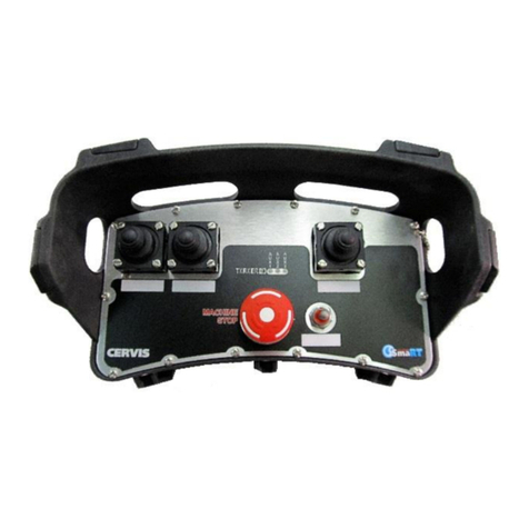
Figure 1. Warrior LRC Wireless Transmitter .............................................................................2
Figure 2. Warrior LRC Transmitter LED Display.......................................................................4
Figure 3. Warrior LRC Control Layout .......................................................................................5
Figure 4. Warrior LRC Battery Installation...............................................................................16
Figure 5. Receiver Decoder Essential Components...............................................................21
Figure 6. System Enable Fault Indicator, Reset Button, and Changeover Switch
Locations ....................................................................................................................25
Figure 7. Pneumatics Enclosure Essential Decoder ..............................................................27
Figure 8. System Controls.........................................................................................................29
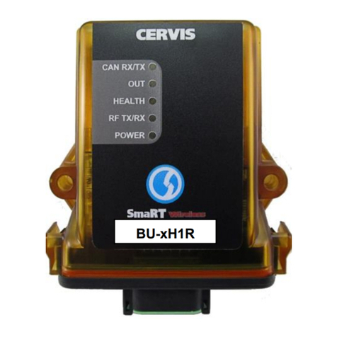
Figure 9. MU-x6E Receiver Inside the Electrical Cabinet.......................................................30
Figure 10. Agency Identification Label Locations ....................................................................33
