Cervis Warrior ETHOS HHMS-9XW08-ND User manual
2020 Cervis, Inc.
ETHOS
HHMS-9XW08-ND
Model Transmitter Manual
™

This document is the property of Cervis, Inc. and cannot be copied, modified, e-mailed, or reproduced without the express
prior written consent of Cervis, Inc.
Cervis, Inc. reserves the right to change this manual or edit, delete, or modify any information without prior notification.
FCC Statements
15.19 – Two Part Warning
This device complies with Part 15 of the FCC rules. Operation is subject to the following two conditions:
(1) This device may not cause harmful interference and
(2) This device must accept any interference received, including interference that may cause undesired operation.
15.21 – Unauthorized Modification
NOTICE: The manufacturer is not responsible for any unauthorized modifications to this equipment made by the user. Such modifications could
void the user’s authority to operate the equipment.
15.105(b) – Note:
This equipment has been tested and found to comply with the limits for a Class B digital device, pursuant to Part 15 of the FCC Rules. These
limits are designed to provide reasonable protection against harmful interference in a residential installation. This equipment generates, uses and
can radiate radio frequency energy and, if not installed and used in accordance with the instructions, may cause harmful interference to radio
communications. However, there is no guarantee that interference will not occur in a particular installation. If this equipment does cause harmful
interference to radio or television reception, which can be determined by turning the equipment off and on, the user is encouraged to try to
correct the interference by one or more of the following measures:
•Reorient or relocate the receiving antenna.
•Increase the separation between the equipment and receiver.
•Connect the equipment into an outlet on a circuit different from that to which the receiver is connected.
Industry Canada Statement
This device complies with Canadian RSS-210.
The installer of this radio equipment must ensure that the antenna is located or pointed such that it does not emit RF field in excess of Health Canada limits
for the general population; consult Safety Code 6, obtainable from Health Canada’s website https://www.canada.ca/en/health-
canada/services/environmental-workplace-health/reports-publications/radiation/safety-code-6-health-canada-radiofrequency-exposure-guidelines-
environmental-workplace-health-health-canada.html.
Le présent appareil est conforme à la norme CNR-210 d'Industrie Canada.
Le programme d’installation de cet équipement radio doit s’assurer que l’antenne est située ou fait telle qu’elle n’émet pas de champ RF dépassant les
limites de Santé Canada pour la population générale ; consulter le Code de sécurité 6, disponible auprès de Santé Canada site Web
https://www.canada.ca/en/health-canada/services/environmental-workplace-health/reports-publications/radiation/safety-code-6-health-canada-
radiofrequency-exposure-guidelines-environmental-workplace-health-health-canada.html.
Industry Canada Statement
This device complies with Industry Canada licence-exempt RSS standard(s). Operation is subject to the following two conditions: (1) this device may not
cause interference, and (2) this device must accept any interference, including interference that may cause undesired operation of the device.
Le présent appareil est conforme aux CNR d'Industrie Canada applicables aux appareils radio exempts de licence. L'exploitation est autorisée aux deux
conditions suivantes : (1) l'appareil ne doit pas produire de brouillage, et (2) l'utilisateur de l'appareil doit accepter tout brouillage radioélectrique subi, même
si le brouillage est susceptible d'en compromettre le fonctionnement.
IC Unlicensed Devices EIRP Statements for Removable Antennas
Part 1: Under Industry Canada regulations, this radio transmitter may only operate using an antenna of a type and maximum (or lesser) gain
approved for the transmitter by Industry Canada. To reduce potential radio interference to other users, the antenna type and its gain should be so
chosen that the equivalent isotropically radiated power (E.I.R.P.) is not more than that necessary for successful communication.
Partie 1 : Conformément à la réglementation d'Industrie Canada, le présent émetteur radio peut fonctionner avec une antenne d'un type et d'un gain maximal
(ou inférieur) approuvé pour l'émetteur par Industrie Canada. Dans le but de réduire les risques de brouillage radioélectrique à l'intention des autres
utilisateurs, il faut choisir le type d'antenne et son gain de sorte que la puissance isotrope rayonnée équivalente (P.I.R.E.) ne dépasse pas l'intensité
nécessaire à l'établissement d'une communication satisfaisante.
Part 2: This radio transmitter (LOBSRF-310) has been approved by Industry Canada to operate with the antenna type listed below with the
maximum permissible gain and required antenna impedance for each antenna type indicated. Antenna types not included in this list, having a
gain greater than the maximum gain indicated for that type, are strictly prohibited for use with this device.
Partie 2 : Le présent émetteur radio (LOBSRF-310) a été approuvé par Industrie Canada pour fonctionner avec les types d'antenne énumérés ci-dessous et
ayant un gain admissible maximal et l'impédance requise pour chaque type d'antenne. Les types d'antenne non inclus dans cette liste, ou dont le gain est
supérieur au gain maximal indiqué, sont strictement interdits pour l'exploitation de l'émetteur.
This product may contain material that may be hazardous to human health and the environment. In
compliance with EU Directive 2002/96/EC on Waste Electrical and Electronic Equipment (WEEE):
•
Do not dispose of the product as unsorted municipal waste.
•
This product should be recycled in accordance with local regulations. Contact local
authorities for detailed information.
•
This product may be returnable to the distributor for recycling. Contact your distributor for
details.

ETHOS Model Transmitter
2020 Cervis, Inc.
i
Table of Contents
Table of Contents.......................................................................................................................... i
List of Figures ............................................................................................................................... i
List of Tables................................................................................................................................. i
Cervis, Inc. Safety Precautions .................................................................................................. ii
1.0 ETHOS Model Transmitter .................................................................................................. 1
1.1 LED Indications................................................................................................................. 2
1.2 Battery Installation............................................................................................................ 3
1.3Battery Warning and Shutdown...................................................................................... 4
1.5System Startup ................................................................................................................. 5
2.0 How to Associate a Transmitter to a Receiver.................................................................. 6
2.1 Celaring a transmitters memory..........................................Error! Bookmark not defined.
3.0 Transmitter Specifications................................................................................................ 10
Appendix A: Exposure to Radio Frequency Energy .............................................................. 11
Appendix B: RF Exposure Considerations ............................................................................. 11
Appendix C: Agency Identification Label Locations.............................................................. 12
List of Figures
Figure 1. Switch Assignments......................................................................................................1
Figure 2. Warnings and Precautions............................................................................................2
Figure 3. Battery Installation.........................................................................................................4
Figure 4. Remote Low Battery Warning and Auto-Shutdown ...................................................4
Figure 5. Agency Identification Label Locations......................................................................12
List of Tables
Table 1. LEDs..................................................................................................................................2
Table 2. Transmitter Specifications............................................................................................10

User Manual
U129.0.0
ii
Cervis, Inc. Safety Precautions
Read and follow all instructions.
Failure to abide by Safety Precautions may cause equipment failure, loss of authority
to operate the equipment, and personal injury.
Use and maintain proper wiring. Follow equipment manufacturer instructions.
Improper, loose, and frayed wiring can cause system failure, equipment damage, and
intermittent operation.
Changes or modifications made to equipment not expressly approved by the
manufacturer will void the warranty.
Equipment owner/operators must abide by all applicable Federal, State, and Local
laws concerning equipment installation and operation. Failure to comply could result
in penalties and could void user authority to operate the equipment.
Make sure that the machinery and surrounding area is clear before operating. Do not
activate the remote control system until certain that it is safe to do so.
Turn off the transmitter and disconnect power from the receiver before attempting
any maintenance. This will prevent accidental operation of the controlled machinery.
Use a damp cloth to keep units clean. Remove mud, concrete, dirt, etc. after use to
prevent obstructing or clogging the buttons, levers, wiring, and switches.
Do not allow liquid to enter the transmitter or receiver enclosures. Do not use high-
pressure equipment to clean the transmitter or receiver.
Disconnect the receiver before welding on the machine. Failure to disconnect the
receiver may cause destruction of or damage to the receiver.
Operate and store units only within the specified operation and storage temperatures
defined in this document’s specifications.
Keep high-energy radio frequency (RF) devices away from transmitters. For instance,
activating high-power communication radios close to transmitters can cause
interference and “false” circuit activation.
Do not key two-way radios while using the transmitter.

ETHOS Transmitter
©2020 Cervis, Inc.
1
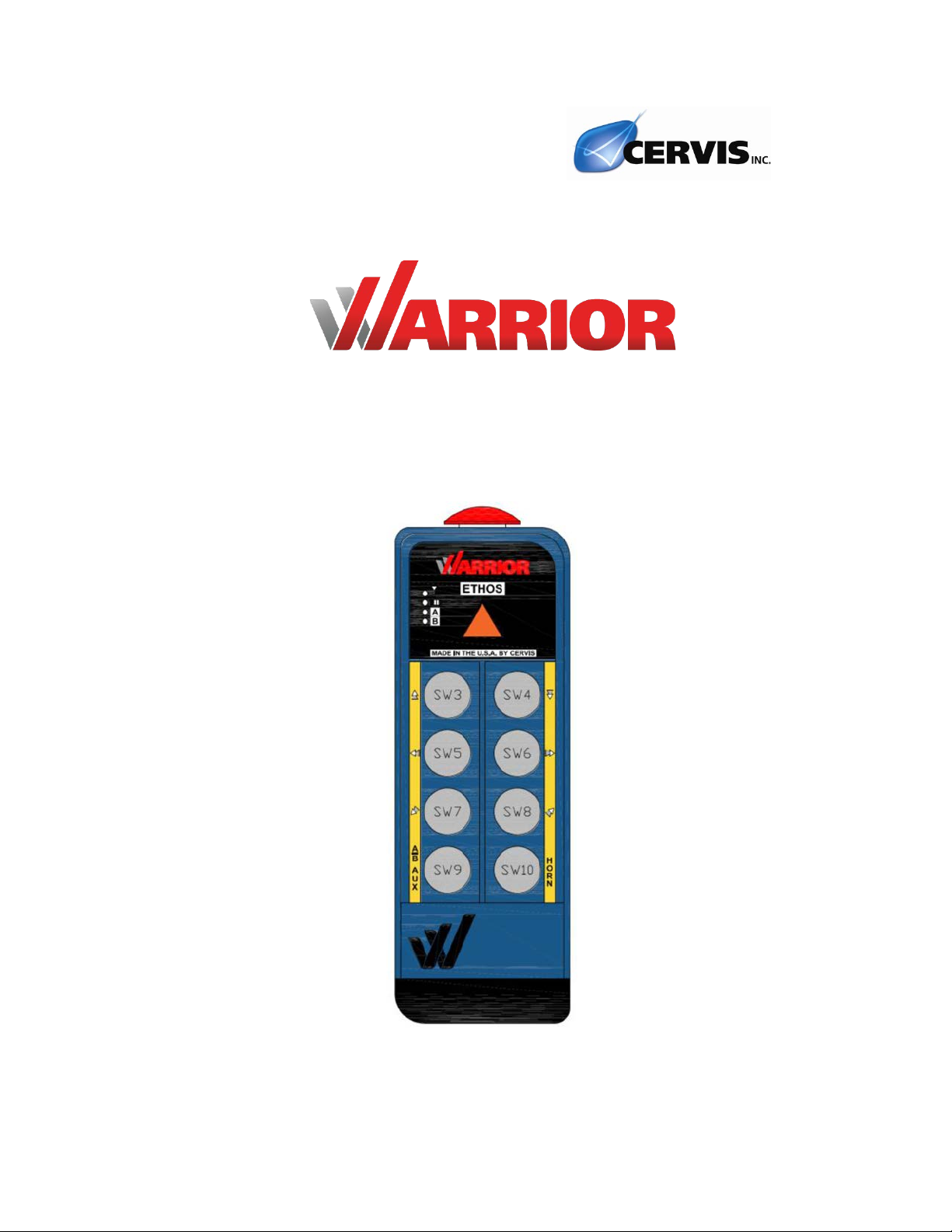
1.0 ETHOS Transmitter
The Warrior ETHOS model transmitter is an industrial transmitter that is designed to provide 3
motion 2 speed crane control with A/B select feature standard.It is specifically offered to work
with the Warrior MU-9x15 model receiver. The ETHOS model has eight dual redundant two step
actuators for motion control.
The transmitter’s vented enclosure is made of an impact resistant plastic, designed to meet an
ingress protection rating of “IP65” according to International Electrotechnical Commission (IEC)
standard 60529. The unit has four diagnostic LEDs that indicate radio frequency (RF)
transmit/receive, Battery status and A selection, and B selection.
Frequency Channel Hopping Direct Sequence Spread Spectrum (CH DSSS) wireless
technology (at 900MHz @ 100mW) allows HHMS-9XW08 transmitters to create a robust link
with Warrior receivers in congested radio environments. These transmitters feature seamless
association to receivers without having to open a machine-mounted receiver.
Figure 1.Switch Assignments
Note: Refer to receiver manual for relay sequence relationships and DIP switch configuration
options.
Trolley Reverse
Trolley Forward
Hoist Up
Hoist Down
A/B Select/AUX
WARNING/START
(B1)
Custom
(B2)
Start
Bridge Reverse
Bridge Reverse
Stop Button
User Manual
U129.0.0
2
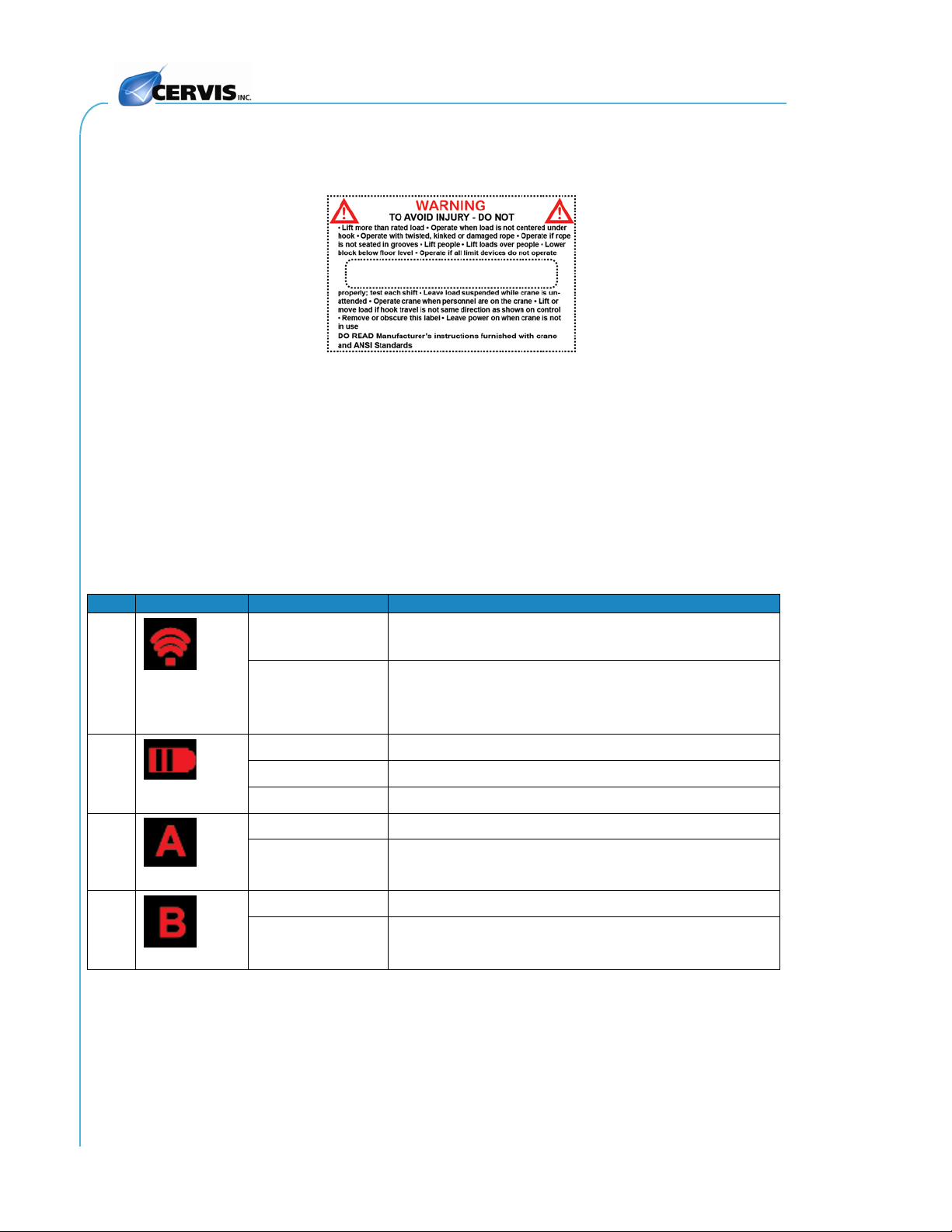
Figure 2 is the label that is permanently attached to the unit’s back side. This label describes
warnings and precautions that must be followed when using the transmitter.
Figure 2. Warrior Transmitter Warnings and Precautions
1.1 LED Indications
The ETHOS model has four LEDs that indicate transmitter status and are also used for
troubleshooting. Table 1 describes each LED.
Table 1. ETHOS model LEDs
LED
Icon
Indication
Meaning
1
Radio
Frequency
(RF)
ON
Transmitter searching for receiver or a button is being
pressed
Flashing Transmitting and receiving messages: communicating with a
receiver. If a lag is occurring, meaning the LED is blinking
and goes solid for short periods it may mean you have a
poor RF connection with the receiver.
2
Battery
OFF Battery strength normal
Flashing Battery LOW
ON LOW Battery Shutdown in Process
3
Selection
OFF A not selected: associated receiver relay OFF
On A selected: associated receiver relay ON
4
Selection
OFF B not selected: associated receiver relay OFF
ON B selected: associated receiver relay ON

ETHOS Model Transmitter
2020 Cervis, Inc.
3
1.2 Battery Installation
Sample photo: display model shown
A rechargeable Lithium Polymer (LiPO) battery pack powers ETHOS transmitters. When
installed and fully charged, the battery supplies power to the transmitter for 80 continuous
operating hours. When installing the battery, be sure that the metallic battery contacts properly
align with those inside the unit.
To install the battery pack in the transmitter body:
1. Pinch the clamps on each side of the battery in.
2. Slide the battery pack into the transmitter body until you hear a click.
Note: Make sure the battery contacts are positioned relative to the front right side of the
transmitter.
To charge the battery pack:
1. Pinch the clamps on each side of the battery in.
2. Slide the battery pack into the battery charger, as illustrated in Figure 3. (Make
sure the battery contacts are oriented correctly with those inside the charger.)
3. Plug the charger into a nearby wall socket.
The LED on the plug indicates charging status.
(Solid Red = charging. Solid Green = charged.
Maximum charging time = Five hours from zero charge.)
4. When the battery has finished charging, unplug the charger from the wall socket,
remove the battery from the charger base, and insert it into the transmitter.

User Manual
U129.0.0
4
Figure 3. Battery Installation
1.3 Battery Warning and Shutdown
The ETHOS transmitter will alert you if the remaining battery life is getting low or is too low for
normal operation.
Figure 4. Remote Low Battery Warning and Auto-Shutdown
LOW BATTERY
The BATTERY LED flashes once per second, indicating a LOW BATTERY situation is
present, recharge the battery pack. The LED continues to flash until the voltage level
drops to 6.1V, when Auto-Shutdown occurs.
Note: The receiver LED quickly flashes three times, once per minute when
transmitter low battery is indicated.
AUTO-SHUTDOWN
The BATTERY LED lights solid for approximately 1.25 seconds before the transmitter
automatically shuts down.
Recharge the battery pack before using the transmitter again.
Shutdown
Lights solid for 1.25 seconds.
Transmitter then shuts down
and can’t be used until the
depleted battery is recharged
or replaced.
Low Battery
Flashes 1x/sec
until Auto-
Shutdown
occurs.

ETHOS Model Transmitter
2020 Cervis, Inc.
5
1.4 System Startup
1. Press and Release the STOP button. (If the STOP is down you only have to
release it).
2. Wait for Radio TX/RX LED to begin flashing (indicates communication with
associated receiver)
3. Press and hold WARNING/START switch until horn sounds or main contactor
closes.
Note: If the Radio TX/RX LED is on solid once you release the STOP switch the handheld
may not be associated to a receiver or the receiver it is associated to may not have power.
4. Once a link is established and the main contactor of the crane is closed you may
commence operation.
At anytime during operation you may press the STOP switch down to STOP
all motion commands. If unsure of anything during operation press STOP
and remove battery and consult factory for support.
User Manual
U129.0.0
6
2.0 How to Associate a Transmitter to a Receiver
Warrior transmitters are associated (or paired) with the receiver at the factory before the system
is shipped. A receiver will only communicate with the transmitters it is associated with.
In the event that you need to ‘move’ a transmitter from one crane to another or put a spare
transmitter into service with a receiver it is not associated to the association process is the
procedure to accomplish this working link.
You may refer to the following receiver manual for additional information if
necessary.
U104 Warrior MU-9X15 Receiver Manual
The process
All Warrior systems use a first come first serve protocol standard meaning more than one
handheld can be associated with a receiver but only one can be in control of the receiver at a
time. To clear a transmitters memory such that it is not associated to a receiver refer to section
2.1.
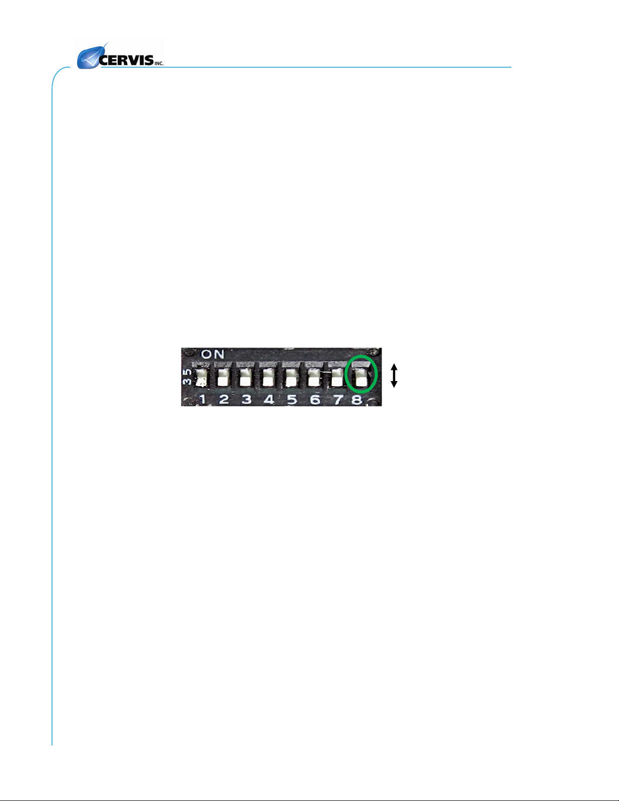
Note: Before attempting association, make sure that receiver S01 DIP Switch #8 in the
desired receiver is set to the ON (1) position.
1. Follow start-up procedure steps 1, release STOP switch
2. When the B LED is ON solid, simultaneously press and release the A/B Select
and WARNING/START switches.
The four LEDs will begin to ‘scroll’ from bottom to top (B, A, Battery, TX/RX)
indicating you are now in the transmitters ‘Maintenance Mode’.
Note: If the B LED goes out before you press the buttons, restart the process
3. Now press and hold Hoist UP and Hoist DOWN buttons for five seconds or until
LED A begins blinking. Once LED A is blinking release the buttons.
The transmitter is now in Association Mode and begins scanning the area for
receivers that are ‘unlocked’ and are available to be associated to. During this
process the transmitter will compile a list of the available receivers. Once this
process is complete the A LED will go out and the B LED will come ON and the
first receiver in the LIST will begin activating its HORN/ASSOCIATION relay
telling you it can be selected.
1
0

ETHOS Model Transmitter
2020 Cervis, Inc.
7
To select this receiver and complete the association process press and release
the WARNING/START switch.
To reject this receiver and move to the next receiver in the list press and release
the A/B Select button. Now the next receiver in the list will begin activating its
HORN/ASSOCIATION relay telling you it can be selected.
If this is the desired receiver press the WARNING/START switch make the
selection. If this is not the desired receiver continue to press and release the A/B
Select until the desired receiver is indicating it can be selected.
Again, once the desired receiver is found press the WARNING/START switch to
confirm the selection.
Transmitters can only be associated with one receiver. If it was associated to a
receiver before the new receiver will overwrite the old receiver and it will no
longer work with the old receiver.
If at any time during the process you become unsure of the activity you are
seeing press the STOP switch, remove the battery and contact the factory
for support.

User Manual
U129.0.0
8
2.1 How to clear a transmitter memory of association
You can erase the transmitters association with a receiver. If this process is completed the
transmitter will not work with any receivers until it is re-associated with a receiver using the
process outlined above. If a transmitter becomes damaged or you need to remove a transmitter
from service, put it in storage or send it in for repair it is recommended that you complete this
process.
1: Follow start-up procedure steps 1, release STOP switch
2: When the B LED is ON solid, simultaneously press and release the A/B Select and
WARNING/START switches.
The four LEDs will begin to ‘scroll’ from bottom to top (B, A, Battery, TX/RX)
indicating you are now in the transmitters ‘Maintenance Mode’.
Note: If the B LED goes out before you press the buttons, restart the process
3: Now simultaneously press and hold Hoist UP, Hoist Down. While holding UP and DOWN
press Trolley Reverse and release all buttons.
The four LEDs will go back to ‘scrolling’ from bottom to top (B, A, Battery, TX/RX)
indicating you are now back in the transmitters ‘Maintenance Mode’.
Press STOP to deactivate the transmitter.
Of this process is completed correctly the transmitter will not work with any receiver. You
can confirm the process is completed by activating the transmitter and the TX/RX LED
should come on SOLID indicating it has no associated receiver in memory. If the TX/RX
LED begins blinking the process was not preformed correctly and the transmitter remains
associated to a receiver, repeat the process.
If at any time during the process you become unsure of the activity you are
seeing press the STOP switch, remove the battery and contact the factory
for support.

ETHOS Model Transmitter
2020 Cervis, Inc.
9

User Manual
U129.0.0
10
3.0 Transmitter Specifications
Table 2. Transmitter Specifications
Item
Description
Power Vin +6V to +8.4V
Source Rechargeable Lithium Ion Battery Pack
Low Battery Warning 6.6V – batteries should be immediately replaced
Low Battery Shutdown 6.1V – batteries must be replaced to operate
Environment Operating Temp -4°F to 140°F (-20°C to 60°C)
Storage Temp -22°F to 158°F (-20°C to 70°C)
Humidity 0–95% non-condensing
Radio Frequency 904–926 MHz @ 100mW
License No license required
Modulation DSSS
Antenna Internal
Enclosure Dimensions 76.2mm x 220.98mm x 42.67mm
3.0" x 8.7" x 1.68"
Weight 1.43 lb. / 650g
Durability High Impact Polymer case
Polycarbonate faceplate
Indicators (See Table 1)
Radio Frequency Indicates wireless communications (transmit/receive)
Battery Indicates battery status
A Indicates Crane A selected
B Indicates Crane B selected
Buttons Eight Two-step pushbuttons, >2M operations

ETHOS Model Transmitter
2020 Cervis, Inc.
11
Appendix A: Exposure to Radio Frequency Energy
Warrior transmitters and machine units contain radio transceivers. When active, a transmitter
sends out radio frequency (RF) energy through its internal antenna. Warrior transmitters and
receivers comply with limits set by the United States Federal Communications Commission
(FCC) for operating distance from human tissue.
Appendix B: RF Exposure Considerations
The radio module may be used in a variety of host applications falling into two general
categories:
1. Mobile applications: Any operating locations where the transmitting equipment is not on
a human body. In mobile applications, the host application is typically fixed to mobile
equipment, with either an internal or external antenna.
2. Portable applications: Any operating locations where the transmitting equipment is
located on the hand, arm, or other part of the human body. In portable applications, the
equipment is either held in the hands of an operator or affixed to either a belt or harness
on the torso.
Equipment containing the radio module was evaluated for RF exposure hazards by two
approaches:
1. Maximum Permissible Exposure (MPE) for mobile applications.
2. Specific Absorption Rate (SAR) for portable applications.
Required separation distances are measured from the actual location of the radiating part of the
antenna. An antenna may be inside the host application, affixed to the host application
enclosure, or at the end of an optional extension coaxial cable.
Mobile Applications
Equipment must be located at least 20cm away from areas likely to be occupied by an unaware
person.
Transmitter Applications
All operators of transmitter equipment with any type of antenna require proper equipment
operation training, and such training must include RF exposure safety instructions. They are
then considered to be “aware” persons once training is completed.
If the portable operating position is on the hand or arm, a 5mm separation is required between
the radiating part of the antenna and nearby human tissue.
Required Training
All installers and operators of host applications that include an SRF310 FT module must be
trained to use proper RF safety precautions as presented in this Appendix.

User Manual
U129.0.0
12
Appendix C: Agency Identification Label Locations
Figure 5. Agency Identification Label Locations

Table of contents
Other Cervis Transmitter manuals


Popular Transmitter manuals by other brands


GEIGER
GEIGER Remote AIR GF2900 Original assembly and operating instructions

Jamara
Jamara SCX Instruction

Pfeiffer Vacuum
Pfeiffer Vacuum CPT 100 operating instructions

Air Monitor
Air Monitor VELTRON III quick start guide

Emerson
Emerson CSI 9420 Reference manual

Drivecon
Drivecon PWR III Series Operation & installation manual


