manuals.online logo
Brands
  1. Home
  2. •
  3. Brands
  4. •
  5. Cerwin-Vega
  6. •
  7. Speakers
  8. •
  9. Cerwin-Vega CVA-121 User manual

Cerwin-Vega CVA-121 User manual

The following guide is a quick reference that will help you to easily set up your Cerwin- ega!
Active speakers. For more information, please read your product’s User Manual.
Before we describe the Cerwin-Vega! Active speakers’ main components check the following instructions:
1. Connect power and audio cables and make sure that the levels are all the way down (at zero).
2. Power on the speaker(s).
3. Verify that you have power via the Power LED.
4. Verify that you have signal. Turning the master level up slightly (we recommend not turning the level past the medium mark (12 o’clock)
until you are sure you have a clean (undistorted) signal.
C A-115, 118, & 121
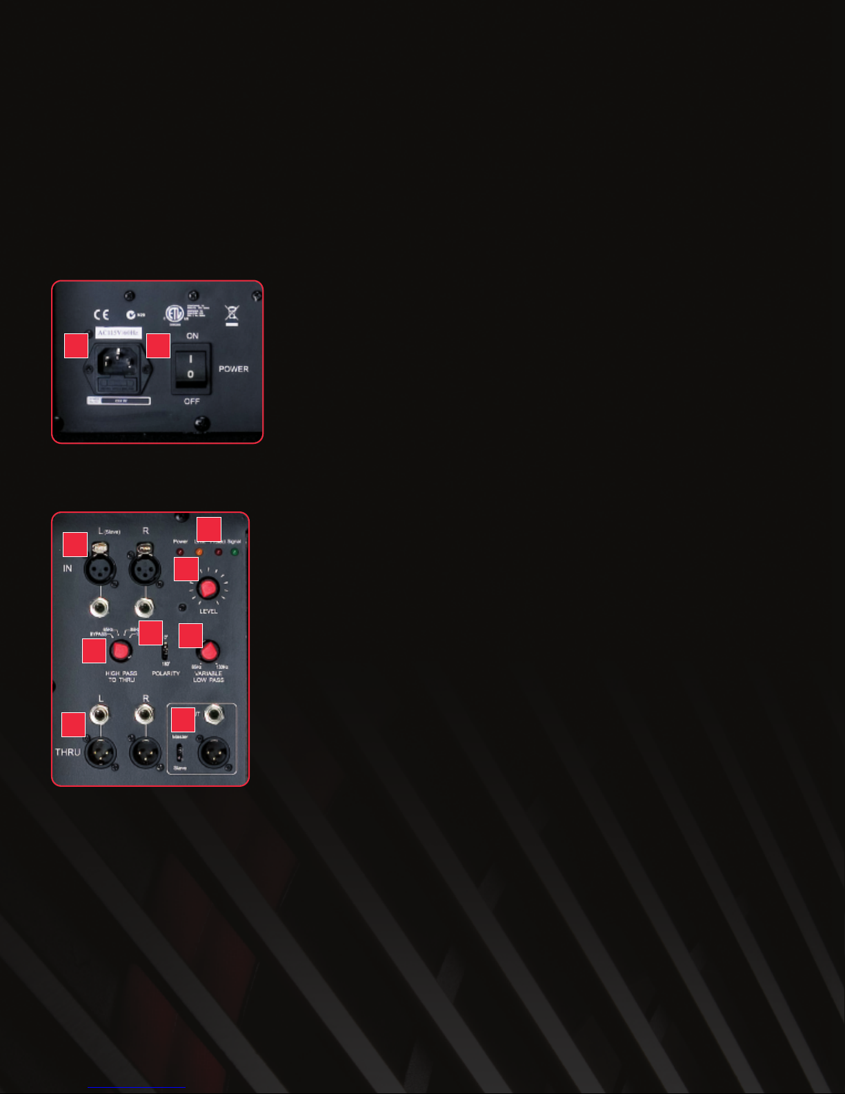
Power Input and Power On / Off (Figure 1)
12
1. Power Input (w/ Fuse)
Connect here the IEC power cord. Do not use other type of power cord.
Note May be hardwired on CVA-121.
2. Power On / Off
Switches the system On and Off. Before powering On, make sure the Level is turned down and
that you have selected the correct signal type in (Mic/DI or Line).
CVA Series Subwoofer Back Panel (Figure 2)
3
45
6
7
8
910
3. Audio Input (XLR or ½”)
Balanced (Left & Right) XLR and 1/4 inch TRS connectors accept signals from balanced or
unbalanced line level or Mic level sources. Signal at In is buffered and routed to Thru.
4. Audio Thru (XLR or ½”)
This Thru signal bypasses the controls and is a buffered output of the In signal. Allows the
signal at In to be routed to a full range top speaker cabinet such as a system matched CVA-28.
Note The High Pass Thru setting affects this signa , if unsure eave in Bypass. P ease see the
description of the High Pass Contro ater in this document.
5. Link Out (XLR or ½”) (w/ Master/Slave switch) (Optional setup)
This output signal is to be used when “daisy chaining” multiple CVA subs. Set the Variable Low
Pass on the first sub and make it the Master; this setting is now passed through the Link Out to
all other subs set on Slave via the Slave input.
6. LED indicators
A. Power Indicator: Illuminates when the system is powered On, (it should remain lit).
B. Limit Indicator: Illuminates when the protection limiter is active, (this may blink
occasionally but should not remain lit).
C. Protect Indicator: Illuminates when the amp has shut down to protect itself.
Tip If this occurs, check the all connections, fuses, and make sure you have proper
amperage in the outlet.
D. Signal Indicator: An audio signal is present at the input, (normally is lit, or blinks).
7. Level
Adjusts the input signal (master volume) to the amplifier (i.e. over all loudness / volume). Make
sure this is not turned up when powering On or when switching the input (Mic/DI – Line).
8. High Pass (to Thru)
Reduces low frequencies in top speaker cabinet that can conflict with CVA sub frequencies. For
a simple yet flexible control, we have made this a four-position switch; the HPF blocks LF
signals below the indicated frequency from reaching the top cabinet (Thru).
Figure 1
Figure 2
9. Polarity Switch
Changes the polarity of the subwoofer, also referred to as the “phase.” Listen and adjust for maximum bass.
10. Variable Low Pass (Sub frequencies)
When sending a full range signal to the subwoofer, the variable LPF blocks HF signals above indicated frequencies from reaching the
subwoofer.
Note This contro on y affects the sub in Master mode, if your sub is in S ave mode it wi receive this setting from the Master sub).
Tip If your sub sounds “muddy” or “muffled” try turning this control counter clockwise to the 9 o’clock position or lower.
C A-121
Parametric EQ for Sub Setup (Figure 3)
41 3
2
The parametric EQ was designed to cut offending frequencies from wall boundary conditions and
or bump frequencies that need more emphasis. For example, when your subs are near a glass
wall or other boundaries that may rattle or shake, or for bands that have a drummer that they may
want to fine-tune the sub to “punch” a specific frequency.
Tip If you are unfamiliar w/ Parametric EQs, do some research about it or leave in the
Bypass position.
1. Gain = Volume / Level:
Turning clockwise increases the overall sound produced.
2. Frequency = the specific frequency being adjusted – the Q parameter works in tandem with
the Q parameter.
Turning clockwise allows for more upper bass and mid range frequencies to be produced.
3. Q = the width of the frequency range being affected.
Turning clockwise narrows the frequency range that is being affected. Turning counter
clockwise widens the frequency range being affected.
4. Bypass / On switch
In the Bypass position, the EQ is not active and the previous controls are null.
Figure 3
1
2
3
4
5
6
7
8
910 11
1. Power (AC) Input (w/ Fuse)
Connect here the IEC power cord. Do not use other type of power cord.
2. Power (AC) Output
Intended to run power for one or two additional CVA-28 units. Never
daisy chain more than three CVA-28’s from a single source!
Note This on y app ies to power cab es – not the audio cab es.
3. Voltage Switch
Allows system to be used with supply voltages of either 110-120 volts
or 220- 240 volts.
Warning Make sure you have selected the correct voltage based
upon your countries standard voltage before you power up your
speaker.
4. Power On / Off
Switches the system On and Off. Make sure the Level is turned down
and that you have selected the correct signal type in (Mic/DI or Line)
before powering On.
Warning Unexpected High pressure sound levels can occur by
sending a line level signal to the C A-28 while the unit is set for a
DI input, such as for an acoustic guitar.
C A-28 (Figure 4)
Figure 4
5. Level
Adjusts the input signal (master volume) to the amplifier (i.e. over all loudness / volume). Make sure this is not turned up when powering
On or when switching the input (Mic/DI – Line).
6. Audio Input (XLR or ½”)
Balanced (Left & Right) XLR and 1/4 inch TRS connectors accept signals from balanced or unbalanced line level or Mic level sources.
Signal at In is buffered and routed to Thru.
7. Audio Thru (XLR or ½”)
This Thru signal bypasses the controls and is a buffered output of the In signal. Allows the signal at In to be routed to another CVA-28.
Notes
1. You must set up the eve contro s on each CVA-28 independent y.
2. When using the High Pass Though (crossover) on a CVA sub, the EQ of the input signa to the CVA-28 is affected un ess the High Pass
Though is set to Bypass.
8. LED indicators
A. Power Indicator: Illuminates when the system is powered On, (it should remain lit).
B. Limit Indicator: Illuminates when the protection limiter is active, (this may blink
occasionally but should not remain lit).
C. Protect Indicator: Illuminates when the amp has shut down to protect itself.
Tip If this occurs, check the all connections, fuses, and make sure you have proper amperage in the outlet.
D. Signal Indicator: An audio signal is present at the input, (normally is lit or blinks).
9. MIC/DI or LINE Switch
This switch allows the input to accept either a line level or a Mic level signal. Mic/DI is for a microphone or instrument Direct Input (i.e.
acoustic guitar outfitted with a pickup). Line is for a line level output from an audio source such as a mixing board or a keyboard.
Warning When adjusting the Mic/DI switch please power Off the unit first or turn the gain all the way down. Adjusting the switch
to the wrong setting while the input gain is up can result in very high SPL levels, which can damage hearing!
10. NO SUB or SUB Switch
Select the No Sub position when a dedicated subwoofer is not being used. This position provides more bass for full range use.
Use the Sub position when a dedicated subwoofer is used. This position reduces some low frequency information that may interfere with
your subwoofer frequencies creating a “muddier” or less-defined sound.
Tip For the best results, experiment with the Sub switch. In the Sub position, it removes bass frequencies below 100 Hz and
allows the C A-28 to play louder with less distortion. For optimum use of this switch, remember to place on the C A sub the High
Pass knob in the Bypass position.
11. OFF or CONTOUR Switch
The Contour switch provides a boost at high frequency & a slight boost to the low end (when the Sub/No Sub switch is in the No Sub
position). When engaged, the switch can be used in quiet environments where lows and highs may need a slight boost; or in situations
where high frequencies need to carry over longer distances. For best results, please experiment with the Contour switch.
Tip If you are using the C A-28 speaker outdoors or in an extremely large venue, you may want to try out the Contour switch. It
provides a slight high frequency boost & enhanced LF range to throw specific frequencies further and louder when needed.
Basic C A Settings Guide:
Note This is not intended for a app ications but an easy way to get good sound from your setup.
Using at least a 20 AMP breaker per stack and all XLR cables, use the following as an average settings guide when using two CVA-28’s
on a dual antler (CVANT-2A) per one CVA-118.
SETTINGS ON THE C A Series SUB:
• LEVEL: set to 12 o’clock position (half way).
• HIGH PASS (to through): set to 85 Hz.
• POLARITY: set to 0 zero (up position).
• VARIABLE LOW PASS: set between the 10 o’clock and 2 o’clock position (just below or slightly above half way).
• LIN OUT: set to Master, (unless you plan to daisy chain multiple subs).
• PARAMETRIC EQ: set to Bypass (up position- only on the CVA-121).
SETTINGS ON THE C A-28:
• LEVEL: set to 12 o’clock position (half way).
• INPUT SWITCH (Mic/DI or Line): set to Line (down position), (unless you are using the CVA-28 by itself w/ a mic or instrument).
• SUB SWITCH: set to No Sub (up position). Remember if you are using the High Pass Thru as the crossover to adjust this for all tops set
to Sub.
• CONTOUR SWITCH: set to Off (up position), (unless you are outdoors and need the loudness).
• AC OUTPUT: use the specified cable to daisy chain power to another CVA-28.
Warning Do not chain more than two other C A-28 per one power source.
Other Tips and Helpful Hints: Depending on the quality of your signal, as you increase volume levels you may experience distortion or
muddiness or notice the limit light stays On more than it is Off.
Please always check the distortion levels of your source signal (preferably with headphones on your master or DJ mixing board).
Remember the front grill is a driver heat-sink, therefore depending on hours of usage and direct sunlight the front grill may feel warm; as
well as the amp heat-sink located on the rear of the speaker. Don’t worry if this happens; just make sure you are not continuously driving
the speaker’s amplifier to distortion levels (see LED indicators).
U.S.A. 3000 SW 42nd St. •Hollywood, FL 33312 •1.954.316.1501
Europe 382 Avenue de la Couronne •1050 Brussels, Belgium •3 2 2 6 4 5 0 5 0 0
www.cerwin-vega.com
CVA-121
CVA-118
CVA-115
CVA-28

Other manuals for CVA-121

2

This manual suits for next models

3

Other Cerwin-Vega Speakers manuals

Cerwin-Vega iNTENSE 252 User manual

Cerwin-Vega

Cerwin-Vega iNTENSE 252 User manual

Cerwin-Vega Vega Series User manual

Cerwin-Vega

Cerwin-Vega Vega Series User manual

Cerwin-Vega CLS Series User manual

Cerwin-Vega

Cerwin-Vega CLS Series User manual

Cerwin-Vega CVi-152 User manual

Cerwin-Vega

Cerwin-Vega CVi-152 User manual

Cerwin-Vega CLS Series CLS-15S Manual

Cerwin-Vega

Cerwin-Vega CLS Series CLS-15S Manual

Cerwin-Vega CLASSIC CLSC-6C User manual

Cerwin-Vega

Cerwin-Vega CLASSIC CLSC-6C User manual

Cerwin-Vega CVXL-115 User manual

Cerwin-Vega

Cerwin-Vega CVXL-115 User manual

Cerwin-Vega XLS Series XLS-12 User manual

Cerwin-Vega

Cerwin-Vega XLS Series XLS-12 User manual

Cerwin-Vega XD4 User manual

Cerwin-Vega

Cerwin-Vega XD4 User manual

Cerwin-Vega XD3 User manual

Cerwin-Vega

Cerwin-Vega XD3 User manual

Cerwin-Vega XLS SERIES User manual

Cerwin-Vega

Cerwin-Vega XLS SERIES User manual

Cerwin-Vega INT-152 Instruction Manual

Cerwin-Vega

Cerwin-Vega INT-152 Instruction Manual

Cerwin-Vega XED693 User manual

Cerwin-Vega

Cerwin-Vega XED693 User manual

Cerwin-Vega STROKER Series User manual

Cerwin-Vega

Cerwin-Vega STROKER Series User manual

Cerwin-Vega CVE Series User manual

Cerwin-Vega

Cerwin-Vega CVE Series User manual

Cerwin-Vega VE-12F User manual

Cerwin-Vega

Cerwin-Vega VE-12F User manual

Cerwin-Vega pro mobile Series User manual

Cerwin-Vega

Cerwin-Vega pro mobile Series User manual

Cerwin-Vega P1500X User manual

Cerwin-Vega

Cerwin-Vega P1500X User manual

Cerwin-Vega V-5M Operation User manual

Cerwin-Vega

Cerwin-Vega V-5M Operation User manual

Cerwin-Vega P1000X User manual

Cerwin-Vega

Cerwin-Vega P1000X User manual

Cerwin-Vega CVX series User manual

Cerwin-Vega

Cerwin-Vega CVX series User manual

Cerwin-Vega Classic Series CLSC-215 User manual

Cerwin-Vega

Cerwin-Vega Classic Series CLSC-215 User manual

Cerwin-Vega Professional ProStax PSX-36 User manual

Cerwin-Vega

Cerwin-Vega Professional ProStax PSX-36 User manual

Cerwin-Vega CVi-218S User manual

Cerwin-Vega

Cerwin-Vega CVi-218S User manual

Popular Speakers manuals by other brands

Celestion Green Label Series BN10-200X Specifications

Celestion

Celestion Green Label Series BN10-200X Specifications

ION SOUND SPLASH quick start guide

ION

ION SOUND SPLASH quick start guide

Califone PowerPro PA916-SP owner's manual

Califone

Califone PowerPro PA916-SP owner's manual

Boston Acoustics Bravo II Center user guide

Boston Acoustics

Boston Acoustics Bravo II Center user guide

cabstone SOUNDSATELLITE USB manual

cabstone

cabstone SOUNDSATELLITE USB manual

PYLE Audio PWMA68 user manual

PYLE Audio

PYLE Audio PWMA68 user manual

Gold Note A6 EVO owner's manual

Gold Note

Gold Note A6 EVO owner's manual

KV2 Audio KT2.0 user guide

KV2 Audio

KV2 Audio KT2.0 user guide

Linn KEILIDH owner's manual

Linn

Linn KEILIDH owner's manual

Planet Audio Lynx Wireless PA100B user manual

Planet Audio

Planet Audio Lynx Wireless PA100B user manual

thomann THE BOX MBA120W MKII user manual

thomann

thomann THE BOX MBA120W MKII user manual

ION TAILGATER SMART user manual

ION

ION TAILGATER SMART user manual

gfm BT90S user manual

gfm

gfm BT90S user manual

MartinLogan classic ESL 9 user manual

MartinLogan

MartinLogan classic ESL 9 user manual

Conceptronic HOYT 03 Series quick guide

Conceptronic

Conceptronic HOYT 03 Series quick guide

Edison PARTYBOX 1200 quick start guide

Edison

Edison PARTYBOX 1200 quick start guide

JBL M5 owner's manual

JBL

JBL M5 owner's manual

Definitive Technology UIW RLS II owner's manual

Definitive Technology

Definitive Technology UIW RLS II owner's manual

manuals.online logo
manuals.online logoBrands
  • About & Mission
  • Contact us
  • Privacy Policy
  • Terms and Conditions

Copyright 2025 Manuals.Online. All Rights Reserved.