CESP CES-J Series User manual

User Manual
Page 1 /11
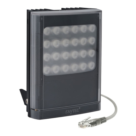
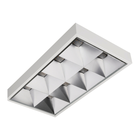
CES-J Series LED Surface-mounted Luminaires
User Manual
SHENZHEN CESP CO., LTD
2020-08

User Manual
Page 2 /11
Applications:
•Wastewater treatment, oil and gas refineries, drilling rigs, petrochemical facilities, food and
beverage facilities, tunnels, outdoor wall and stanchion mounted general area lighting, and
where flammable vapors, gases are present.
•Applies to hazardous locations of Class I, Division 2 with explosive gas atmosphere.
•Applies to marine locations, non-recessed outside type (salt water).
Features:
•Industry-leading efficacy: up to 110 LPW;
•CTT: 3000K-6500K;
•CRI: ≥70;
•-40°C to +40°C Ambient operating temperature;
•
Low profile fixture;
•Flush, swivel and pole mount options;
•Wide optics for uniform illumination;
•Fxture warranty;
•Entry Size: NPT 3/4”-14;
•Beam angle: 108°, 120°;
Standard Materials:
•Housing –Aluminum alloy (ADC12 );
•Lens –tempered glass;
Mounting (ordered separately):
Versatile mounting options:
•Ceiling mount
•Drop mount
•Pole mount
•Wall Mount
Mounting Angle:0°to ±90°;
Certifications and compliances for hazardous locations:
NEC/CEC:
• Class I, Division 2, Groups A, B, C and D;
•T-Class: T6 for Models CES-J100 and CES-J40S, T5 for Model CES-J200;
• Damp and wet locations;
• Certification body:UL
• Certification Mark:CUL
• Certificate No:E475887
Standard :
US: UL 844; UL 1598;

User Manual
Page 3 /11
Canada: CSA C22.2 No. 137; CSA C22.2 No. 250.0;
Certifications and compliances for marine locations:
NEC:
• Damp and wet locations;
• Certification body:UL
• Certification Mark:UL
• Certificate No:E495071
Standard :
US: UL 1598A; UL 1598;
Warning:
CUL for Hazloc:
⚫SUITABLE FOR WET LOCATIONS;
⚫THIS LUMINAIRE IS ACCEPTABLE FOR OPERATION IN AMBIENT CONDITIONS NOT EXCEEDING
40°C;
⚫FOR SUPPLY CONNECTION, USE WIRES RATED FOR AT LEAST 90°C;
⚫NO SERVICEABLE PARTS” OR “NO USER SERVICEABLE PARTS. DO NOT OPEN FOR CLEANING.;
⚫CAUTION - ″TO REDUCE THE RISK OF IGNITION OF HAZARDOUS ATMOSPHERES, DISCONNECT
THE LUMINAIRE FROM THE SUPPLY CIRCUIT BEFORE OPENING. KEEP TIGHTLY CLOSED WHEN IN
OPERATION.″;
⚫THIS PRODUCT MUST BE INSTALLED IN ACCORDANCE WITH THE APPLICABLE INSTALLATION CODE
BY A PERSON FAMILIAR WITH THE CONSTRUCTION AND OPERATION OF THE PRODUCT AND THE
HAZARDS INVOLVED;
⚫“CAUTION –RISK OF SHOCK” and “DISCONNECT POWER BEFORE SERVICING”.
UL for marine locations:
⚫OUTSIDE TYPE or OUTSIDE TYPE (SALT WATER);

User Manual
Page 4 /11
Technical table:
Model
Power
(W)
Input voltage: AC100V-277V; Frequency: 50/60Hz;
Output voltage: 33V~42Vdc;
CCT:3000K-6500K
Power factor:0.97
Luminous
flux (LM)
Light
efficiency
(Lm/W)
LEDs Chip
LEDs Type
(3V)
Weights
(kg)
Size(mm)
L x W x H
CES-J40S
Pmax ≤
45W
≥4400
110
36PCS
3030
4
200x200 x 147
CES-J100
Pmax ≤
105W
≥11000
110
84PCS
3030
7.5
300x300 x 165
CES-J200
Pmax ≤
200W
≥20350
110
156PCS
3030
10.5
400x400 x 169
Dimensions:
Figure 1 applies to CES-J40S.
L x W x H: 200mm x 200mm x 147(195.5)mm
Figure 1
Figure 2 applies to CES-J100.
L x W x H: 300mm x300mm x 165(251)mm

User Manual
Page 5 /11
Figure 2
Figure 3 applies to CES-J200.
L x W x H: 400mm x 400mm x 169(248)mm
Figure 3
Mounting:
The product can be mounted as shown in Figure 4 -6 below.
U-Bracket Size, applies to CES-J40S:

User Manual
Page 6 /11
Figure 4
U-Bracket Size, applies to CES-J100, CES-J200:
Figure 5
U bracket mounting:
1. The mounting method of M10X60MM
expansion bolt as shown on the right:
Two M10X60MM expansion bolts can
be installed in the wall mounting
position, the distance between two
bolts is 75-160MM

User Manual
Page 7 /11
The product can be mounted as shown in Figure 6 below.
2. Make the mounting holes of U
bracket through the expansion bolt
heads, putting in the spring washer and
screw on the nuts. Make fully tighten
between and explosion bolts with the
wall by the wrench. Expansion bolts
must be able to withstand four times
the weight of the light fixture.

User Manual
Page 8 /11
Figure 6
Appearance and Cable gland connection chart :
Front view
a) Connect the equipment’s using suitable cable gland and armored cable.
U bracket
REFLECTOR
TEMPERED GLASS
Triangle frame

User Manual
Page 9 /11
Type A (With 1pc cable gland)
i) Choose the accurate cable section and cable glands for the appropriate mounting
type features.
ii) Do not use the equipment on the fittings that have a lower protection class.
iii) Use the suitable cable series according to the equipment inlet diameter or cable
diameter.
b) Do the mounting of the equipment parts by using the sealed piping system.
Type B (Without cable glands, pipe mounting as the above Figure 6)
i) Use the accurate cable section for the appropriate mounting type features.
ii) Do not use the equipment on the fittings that have a lower protection class.
iii) Equipment mounting charts were given on the Figure 6.
iv) Subsequent to the completion of the fittings works. the equipment is checked and
sealing is applied.
v) Please implement reading the instructions carefully.
Energy connection chart:
- Put on the cable gland or conduit before the installation,
COVER
POWER BOX
BODY
CABLE GLAND

User Manual
Page 10 /11
- Do not remove the cover without cutting of the energy.
- In the case that deformation occurs on the equipment due to misuse or improper mounting,
do not remove the cover and the frame.
- Make the product electrical cable connections as shown below.
Use and maintenance:
1) Clean up
Please keep light fixtures clean during use, whether the external or internal. Also do not allow
water and oil into light fixtures.
The light fixture shall be inspected regularly (at least once a year) for junction boxes and glass
covers according to the condition of site. Dust shall be removed with compressed air using a
hand bellows or a hose with a wooden or rubber nozzle.
If one or more electrical components of the luminaire fail, please contact the manufacturer as
soon as possible.
L=Live N=NEUTRAL
Thread=NPT 3/4″
Ground wire area 2.5 mm²

User Manual
Page 11 /11
2) Flame-proof surface
Pay attention to protect the flameproof surface, do not damage or corrosion it, otherwise the
safe operation can not be guaranteed. Please contact the manufacturing company as soon as
possible.
3) Bolt
Always check the tightening degree of all bolts, especially the bolts fixing the explosion-proof
part and the rotating part must be in a tight state.
Storage and transportation of light fixtures:
Light fixtures are packed into strong wooden boxes or cardboard boxes by the manufacturer,
then shipped. The packaging shall not be dismantled during transportation. The lamp shall be
cleaned of dust spots immediately after the packaging is removed and the exposed surface shall
be wiped clean.
When carriage, light fixtures must be prevented to invert to avoid damages.

User Manual
Page 12 /11
Ordering information:
CES-J W-A-B-C-D-E
CES- SHENZHEN CESP;
J- Series ;
W-Power, 40S: 40W; 100:100W; 200:185W;
A- Certification type, 01: CUL UL844 C1D2; 02: ATEX Zone 1/21; 03: IECEx Zone2; 04: UL1598A;
B- CCT, 01:3000K; 02: 4000K;03: 6500K; 04: 5000K; 05: 5700K….;
C- Mounting, 01: U bracket mount; 02:Pole mount; 03:Other mount…..;
D-Color, 01: Yellow; 02: Gray; 03: White; 04: Green; 05: Blue; 06: Orange red…;
E-Other;
Part number example: CES-J100-03-05-01-02; That means 100W, Certification type is IECEx
Zone2, CCT 5700K, U bracket mount, Gray.
Address:6Th Fl Wangcheng Bldg, Longhua St, Longhua District, Shenzhen, Guangdong, CHINA
This manual suits for next models
3
Table of contents