CESVA CV110 User manual
User’s manual
CV110
Vibration Calibrator
M_CV110_v0004_20170113_EN

MANUAL DEL USUARIO
USER’S MANUAL
BENUTZERHANDBUCH
MANUEL D'INSTRUCTIONS
MANUALE D’USO
MANUAL DE L’USUARI

CV110
User’s manual
1
ENGLISH
CONTENTS
1. GENERAL DESCRIPTION................................................................................................ 2
2. CONTROLES Y ELEMENTOS ......................................................................................... 3
3. RECEPTION OF THE VIBRATION CALIBRATOR........................................................... 5
4. SCREEN........................................................................................................................... 5
5. OPERATION..................................................................................................................... 6
5.1 Verification process..................................................................................................... 6
5.1.1 Verification of VC431 vibrometer....................................................................... 7
5.1.2 Verification of SC310 with module VM310......................................................... 8
5.2 Battery........................................................................................................................ 9
5.2.1 Battery maintenance ......................................................................................... 9
6. TECHNICAL SPECIFICATIONS......................................................................................10
6.1 Technical specifications.............................................................................................10
6.2 Included accessories .................................................................................................11

2
1. GENERAL DESCRIPTION
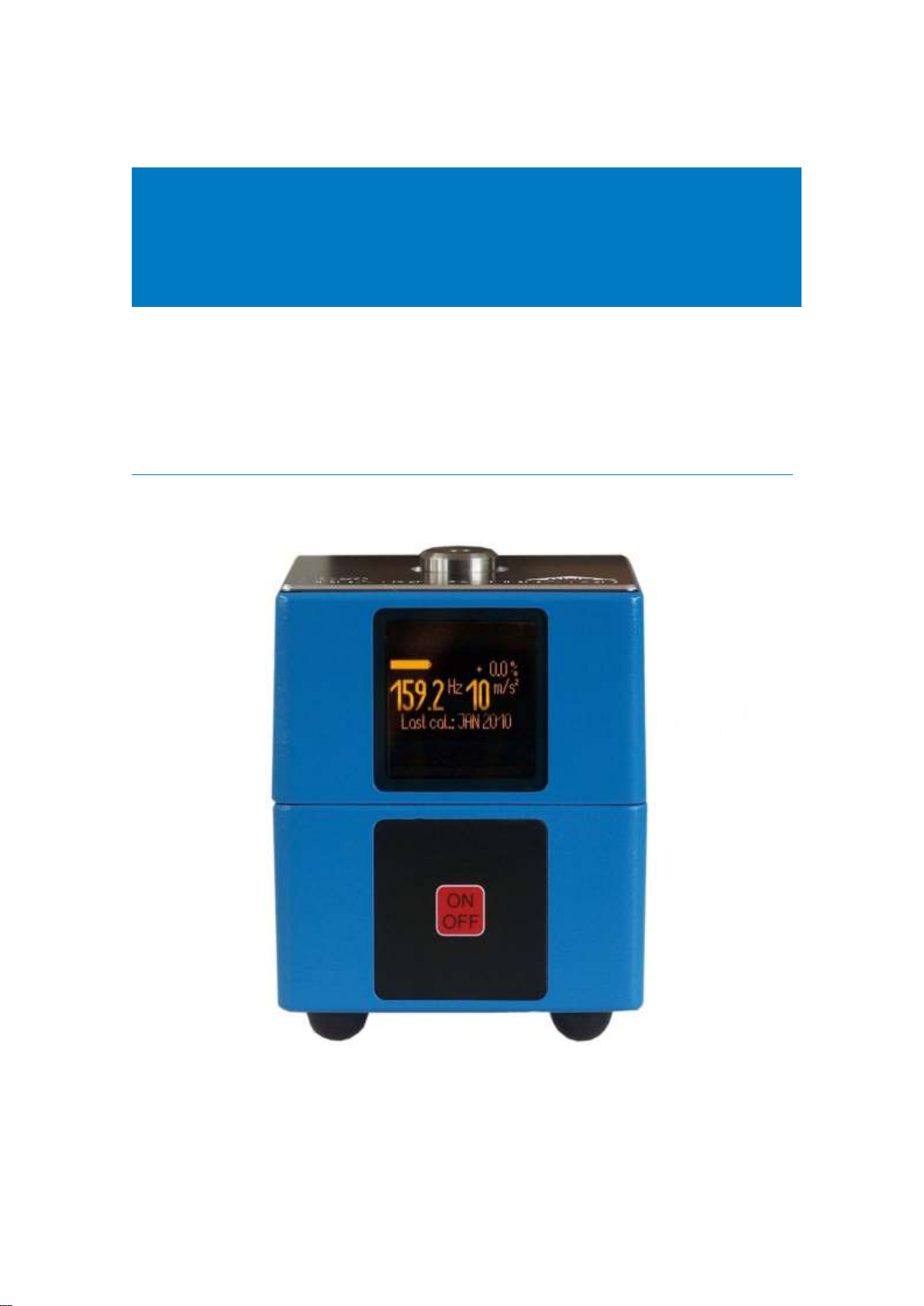
The CV110 calibrator for vibration is a precision and a user friendly instrument
that allows you to verify vibrometers quickly and efficiently.
The crystal-quartz of the CV110 vibration calibrator generates stable and accurate frequency
vibration of the calibrator. A reference accelerometer inside the shaker head and a control
circuit keep the vibration level constant and independent of the weight of the fixed
accelerometer.
The CV110 allows calibrating accelerometers with: (m/s2) acceleration units, (mm/s) velocity
units and (µm) displacement units with nominal values of: 10 m/s2, 10 mm/s and 10 µm. The
frequency of vibration is =1000 rad/s (f=159.15 Hz). The vibration calibrator allows
accelerometers weighting up to 500 g.
The CV110 vibration calibrator has rubber pads in order to insulate it from vibrations
transmitted through the contact surface.
The internal battery of the CV110 vibration calibrator makes it suitable for verifying
accelerometers on the measurement site.
The transport briefcase supplied together with the CV110 allows its easy and comfortable
transportation.
CV110
User’s manual
3
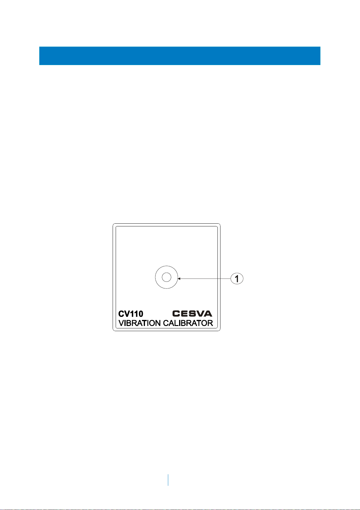
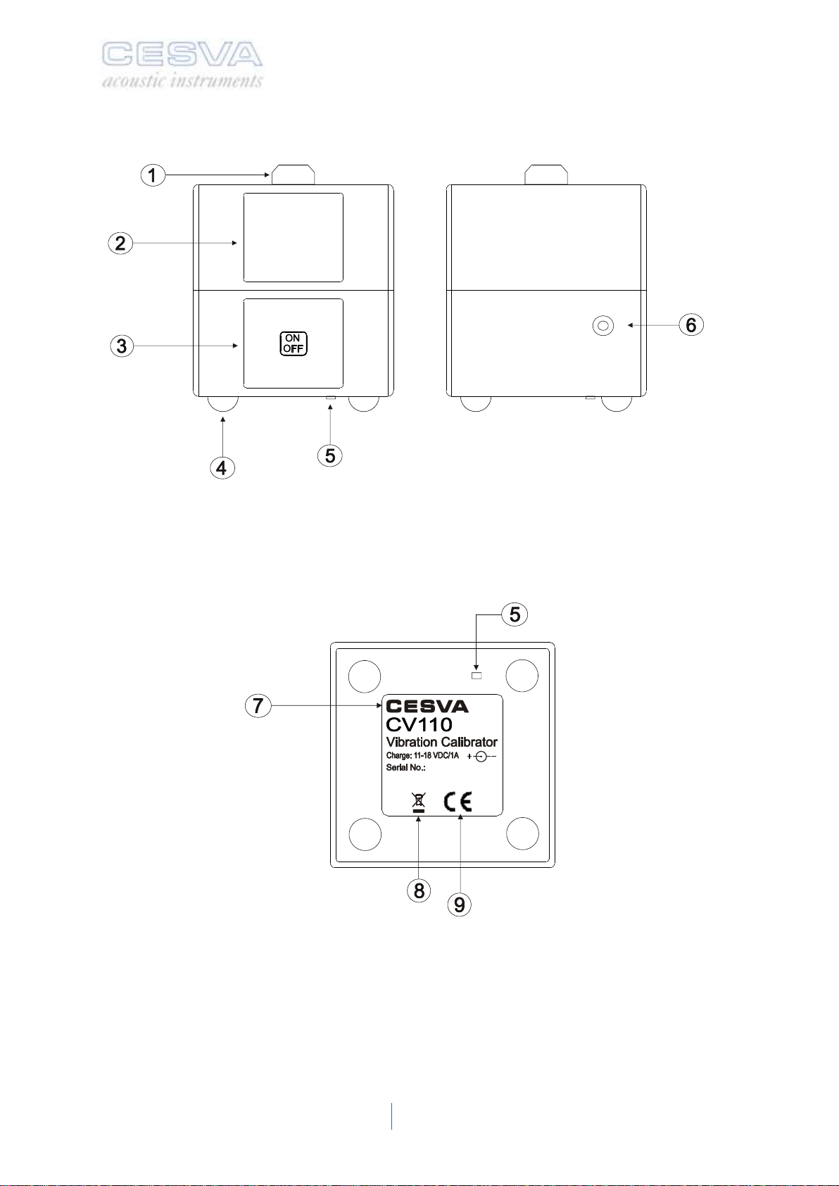
2. CONTROLES Y ELEMENTOS
1. Shaker head. Head for fixing accelerometers.
2. Screen of calibrator.
3. On/Off switch.
4. Rubber legs. Rubber legs for insulating the CV110 from vibration.
5. Reset button. Button to reset the computer.
6. DC power input. Input for connecting the 15 VDC mains plug adapter.
7. Equipment characteristics. Space reserved for computer characteristics. It details the
make, model, voltage and serial number from it.
8. WEEE Mark. Symbol indicating separate collection for electrical and electronic equipment.
9. CE mark. European approval mark.
Top view
4
Front / Side view
Base
CV110
User’s manual
5
3. RECEPTION OF THE VIBRATION CALIBRATOR
When receiving the vibration calibrator check that has the following material:
The CV110 vibration calibrator
Transport briefcase
Fastening adapter set
Power adapter
This user’s manual
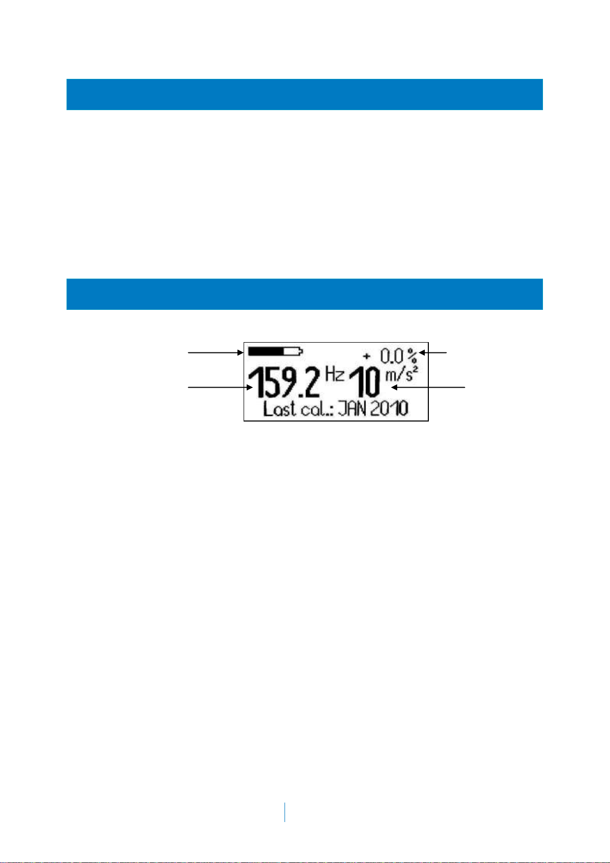
4. SCREEN
battery indicator margin of error
frequency of vibration vibration
magnitude

6
5. OPERATION
Before beginning the verification process be sure that the accelerometer is correctly fixed to
the shaker’s head. To ensure this you can use some stud bolt adapters with different metrics
supplied together with the calibrator. Magnetic and adhesive fixing is allowable only for
estimate calibrations. Accuracy is guaranteed only for screw fixing.
It is very important mounting the accelerometer with symmetrical distribution from the main
axis of the calibrator, otherwise the vibrating system may be deflected from its main axis.
5.1 Verification process
If you already have the triaxial vibrometer VC431 of or the module for
measurement of vibration of the SC310 spectrum analyser then follow the next
steps:
1. Start up the calibrator: press the "ON/OFF" button until the calibrator display lights up. The
screen displays the following information: software and hardware version.
Note: In the unlikely event that the "ON/OFF" does not work, you must press the reset button. This
is on the underside, near the keyboard. Press carefully with a thin object and no-metallic. The
action of pressing the reset button does not affect the accuracy of the calibrator.
2. Then the calibrator shows the next screen where you must check the status of the battery
by means the battery indication located in the upper left part of the screen. In the upper right
part shows the percentage of the margin of error of the vibration magnitude. After a short
period of time, this percentage should reach the value 0%. If the absolute error over 3%, the
calibrator generates an acoustic beep indicating that it is no possible to perform the
calibration process.
3. Wait for a few seconds until the vibration signal stabilises, and the display show the
vibration magnitude and frequency generated by the calibrator at that moment.
If the weight of the accelerometer exceeds the maximum allowed, appears in the upper right
of the screen the message “OVERL”.

CV110
User’s manual
7
5.1.1 Verification of VC431 vibrometer
a) Place the accelerometer in the head of the CV110. It will suffice to press the
accelerometer against the calibrator head with the hand. Although it is advisable to
connect the accelerometer with a screw or by using a mounting magnet.
b) Take the VC431 to the main menu, and use the arrow buttons to select the sensitivity
adjustment icon and access it with the button.
The vibrometer display will show the level of RMS acceleration measured in each one of the
applications and on each one of its axes. You must know which application and which axis is
being measured at all times.
The tolerance for the reading of nominal acceleration is 5%. This means that for example if
you select an acceleration of 10 m/s2on the calibrator this acceleration value may be
between 9.5 and 10.5 m/s2for correct verification in the direction and application evaluated. If
the reading value is not in this range, the sensitivity of the vibrometer needs to be adjusted.
Otherwise the vibrometer is measuring properly and sensitivity need not be readjusted.
NOTE: The vibrometer's sensitivity can only be adjusted by authorised and technically qualified
personnel. The readjustment of sensitivity leads to loss of traceability in the calibration of the unit.
The pictures below illustrate how to check the AC031 accelerometer:

8
5.1.2 Verification of SC310 with module VM310
a) Couple the accelerometer to the CV110. See next figure:
b) Screw the cable to the accelerometer. See next figure:
c) Turn on the calibrator.
d) Next, press to access to the SC310 menu.
e) Select the option SETTINGS SENSITIVITY ADJUSTMENTS
ACCELEROMETER ADJUSTMENT from the SC310 menu
f) The acceleration level measured by the SC310 will appear on the screen, this
acceleration level is measured without frequency weighting.
The calibrator’s accuracy is 5 %. This means that if select a vibration of 10 m/s2, the correct
verification interval value is from 9.5 to 10.5 m/s2.
1
2

CV110
User’s manual
9
g) Verify that the reading value is 140 dB (corresponding to the nominal acceleration
value of 10 m/s2).
5.2 Battery
To charge the battery, connect the supplied mains plug adapter to the charge socket at the
side of the case of the CV110 calibrator.
The battery indicator is located in the upper left hand corner of the display. If the level
indicator is full, the battery level of calibrator is optimal. Instead, if the indicator is empty, the
calibrator needs to be recharged. When the battery level drops under a critical value, the
CV110 is switched off automatically.
Battery indicator
The full battery providing power for approximately 5 hours of operation.
The charging process will take about 3 hours. During the charging process the battery
indicator will be continuously moving. A permanent charging ensures long battery life.
It is possible to use the calibrator during the charging process, however this may slow down
the time needed for a full charge.
5.2.1 Battery maintenance
If constant charging is not possible, and if the calibrator is not used often, the calibrator
should be charged for one day once or twice a year.
If the typical running time can not be reached at a full charging period then you must contact
your nearest official technical service.
the operating time with a fully charged battery becomes insufficient, the battery should be
replaced. In this case, you must contact your nearest official technical service.
10
6. TECHNICAL SPECIFICATIONS
6.1 Technical specifications
Technical specifications
Vibration frequency
159.15 Hz
Vibration magnitude (RMS values)
10 m/s2
Accuracy of frequency
± 0.05 %
Harmonic distortion
< 1%
Settling time
< 10 s
Transverse vibration
< 10%
Maximum weight (g)
500 g
Vibration system:
Dynamic force
Maximum torque
Nominal torque
Maximum transversal force
10 N
2 Nm
1 Nm
20 Nm
Magnetic scatter field at shaker
< 0.2 mT
Mounting of test accelerometer
Magnetic clamp
M5 (7mm deep), 90º ± 0.5%
Temperature range
3% accuracy
5% accuracy
0 to +40 ºC
-10 to +55 ºC
Humidity range
< 90% at 30 ºC (no condensation)
Protection grade
IP 30
Power supply
Built-in accumulator
Battery features
NiMH accumulator
7.2V / 1.6 Ah
Charge socket
DIN 45323 (5.5 / 2.1)
Positive Terminal at center pin
Charge voltage
11 to 18 V DC
Charge current
< 1 A

CV110
User’s manual
11
Running hours with one battery charge
5 hours with m=100g
Automatic shut-off timer
10 minutes
Dimensions
length x width x height
100 x 100 x 120 mm
Weight
2.2 kg
as an electric or electronic equipment manufacturer informs you that the
product you have purchased has been put on the market later than 13 August 2005 and
complies with 2002/96/CE and 2003/108/CE directives about Waste from Electrical and
Electronic Equipment (WEEE).
Also, the product is marked with the following symbol, which indicates that this
one is subjected to separate collection.
6.2 Included accessories
Transport briefcase
DC adaptor
Stud bolt adapters

12


Reserves the right to modify the characteristics
and accessories of this manual without a previous advice,.
Maracaibo, 6 –08030 BARCELONA (ESPAÑA)
Tel. (+34) 934 335 240 –FAX (+34) 933 479 310
e-mail: in[email protected]
www.cesva.com
Table of contents
Other CESVA Test Equipment manuals


