CG AIR IC-TMSV-120/60 Manual

INSTALLATION & OPERATING INSTRUCTIONS FOR ELECTRONIC CONTROLS
IC-TMSV-120/60, IC-TMSV-120/60-L & IC-TMSV-240/60
IC-TMSPV-120/60, IC-TMSPV-120/60-L & IC-TMSPV-240/60
IMPORTANT: KEEP FOR WARRANTY
____________________________________________________________________________________________________________________________________________
Bathtub manufacturer Purchase date
____________________________________________________________________________________________________________________________________________
Dealer name Phone
____________________________________________________________________________________________________________________________________________
Electronic control model and serial number
____________________________________________________________________________________________________________________________________________
Blower model and serial number Pump model and serial number
TMSV > VARIABLE & P/VARIABLE
ENGLISH
2013-01-04
Thank you for your confidence in CG AIR SYSTÈMES INC. We can assure you that CG AIR SYSTÈMES INC. uses the best materials and applies the most
strict quality control measures to ensure that each and every unit meets the highest standards of quality. Furthermore, all CG AIR SYSTÈMES INC. com-
ponents comply with the requirements of the Canadian Standards Association (CSA) and Underwriters Laboratories (UL).
FUNCTIONS
The system will stop automatically after 20 minutes.
PUMP MODE:
Optional water level detectors:
Strategically installed in the bathtub, these will prevent your pump from
starting without the minimum water required.
BLOWER MODE:
Advanced function: An automatic drying cycle will start 20 minutes after
the blower is turned off.
Optional water level detectors: These activate a drying cycle 20 minutes
after the bathtub is emptied even if the system was not used.
FUNCTIONS: SINGLE SYSTEM (1 KEYPAD TO ACTIVATE 1 TMS CONTROL)
TMS KEYPAD - VARIABLE SPEED TMS KEYPAD - VARIABLE SPEED WITH AUXILIARY OUTPUT
}Press once to start the blower or the pump.
}Press a second time to stop
the blower or the pump.
}Press and hold 3 sec., speed will gradually vary
between maximum and minimum.
}Press and hold 6 sec., speed will go directly
to minimum and then straight back to maximum.
}Press and hold this key to increase or decrease
the blower or the pump speed until desired level.
}Press this key to start or stop the auxiliary equipment.
They always start at maximum speed.
TMS KEYPAD - 1 SPEED TMS KEYPAD - 1 SPEED WITH AUXILIARY OUTPUT
}Press this key to start
the blower or the pump
}Press this key to stop
the blower or the pump
}Press this key to start or stop
the auxiliary equipment.
}Press this key to start
the blower or the pump.
}Press this key to stop
the blower or the pump.
Here is an example of a keypad
which activates two TMS controls:
1 VARIABLE
SPEED CONTROL
+
1 SPEED CONTROL WITH
AUXILIARY OUTPUT
Depending on which control
is used to operate the system,
button icons may differ.
}Press this key to start or stop
the blower or the pump.
}Press and hold this key to increase
or decrease the blower or
the pump speed until desired level.
}1st press; speed will vary gradually
from maximum to minimum.
}2nd press; speed will go directly to minimum
and then straight back to maximum.
}3rd press; returns to maximum speed.
FUNCTIONS: DOUBLE SYSTEM (1 KEYPAD TO ACTIVATE 2 TMS CONTROLS)

CAUTION
1. Read these instructions and rules carefully. Failure to follow them could
cause a unit malfunction. Warning! A malfunction could cause serious
bodily injuries, and/or property damages.
2. Check your local electrical safety and plumbing codes. The installation
must comply with these guidelines.
3. No modifications, additions or deletions should be made to the elec-
tronic control without factory approval.
4. This electronic control should not be located near a heat source
except for pumps, blowers or other electronic controls.
5. Wiring should be permanent. Do not use an extension cord. Have the
electrical part of the installation done by, or approved by, a qualified
electrician.
6. Always shut off the electrical power to the breaker panel before servicing.
7. Ensure that a Class A ground fault circuit interrupter (G.F.C.I.) is installed
as part of the wiring.
INSTALLATION
1. For an electronic control not provided with NEMA plugs, connect the
factory pre-installed 14/3 type SJ cable to a junction box (not provided
by the manufacturer). Depending on your model, run a separate 120V,
60Hz, 15A max or 240V, 60Hz, 15A max G.F.C.I. (Class A protected)
electric circuit from the main fuse box to the junction box. Use a 14
gage cable with 3 conductors (2 wires plus ground) in connections up
to 100 feet (30,4m) from the main fuse box. Refer to your local electrical
code if the distance between the installation site of the bathtub unit
and the main fuse box is more than 100 feet (30,4m).
2. IMPORTANT: Locate the side to be placed on top as indicated on the
control box (UP/HAUT). Fix the electronic control box firmly with two
screws.
3. Connect the keypad to the control box cable (indicated by the word
“KEYPAD” on the control box).
4. Connect the power output cable to the blower or pump. Use a junc-
tion box if your electronic control and/or blower or pump are not pro-
vided with molded plugs.
5. Connect the terminal lug on the heatsink to the ground with an
uninsulated wire of 8 gage minimum.
6. Verify connection and functioning of all components of the system
before finalizing the installation.
7. The auxiliary output option makes it possible to connect a piece of
equipment of 120Volts / 0,5Amp maximum. (Only available with
120V/60Hz control)
8. For optional water level detectors, see section WATER LEVEL DETECTORS.
OPTIONAL: WATER LEVEL DETECTORS
WALL OUTLET OR
JUNCTION BOX DEPENDING
ON INSTALLATION
OPTIONAL WITH
120V/60HZ CONTROL
AUXILIARY
EQUIPMENT
120 VOLTS
0,5AMP
MAXIMUM
MAIN BREAKER
PANEL
120V-240V/60Hz
3/14 AWG
14/2 AWG
ATTENTION, THIS GROUND
CONNECTION TO THE HEAT
SINK IS REQUIRED WHEN
GROUND LOG IS PRESENT
ELECTRONIC CONTROL
KEYPAD
CONNECTORS
IMPORTANT:
15A/120V GROUND FAULT CIRCUIT INTERRUPTER CLASS "A".
OPTIONAL: WATER LEVEL DETECTORS
WALL OUTLET OR
JUNCTION BOX DEPENDING
ON INSTALLATION
OPTIONAL WITH
240V/60HZ CONTROL
AUXILIARY
EQUIPMENT
240 VOLTS
0,5AMP
MAXIMUM
MAIN BREAKER
PANEL
120V-240V/60Hz
3/14 AWG
14/2 AWG
ELECTRONIC CONTROL
KEYPAD
CONNECTORS
ATTENTION, THIS GROUND
CONNECTION TO THE HEAT
SINK IS REQUIRED WHEN
GROUND LOG IS PRESENT
IMPORTANT:
15A/240V DOUBLE POLE BREAKER WITH GROUND
FAULT CIRCUIT INTERRUPTER CLASS "A".
INSTALLATION: SINGLE SYSTEM (1 KEYPAD TO ACTIVATE 1 TMS CONTROL)
INSTALLATION FOR UL AND CSA CERTIFICATIONS - 120 VOLTS
INSTALLATION FOR UL AND CSA CERTIFICATIONDS- 240 VOLTS

IMPORTANT:
15A/240V DOUBLE POLE BREAKER WITH GROUND
FAULT CIRCUIT INTERRUPTER CLASS "A".
MAIN BREAKER
PANEL
120V-240V/60Hz
OPTIONAL: WATER LEVEL DETECTORS
OPTIONAL: WATER LEVEL DETECTORS
OPTIONAL WITH
120V/60HZ CONTROL
AUXILIARY
EQUIPMENT
120 VOLTS
0,5AMP
MAXIMUM
120 VOLTS
0,5AMP
MAXIMUM
14/2 AWG
3/14 AWG
3/14 AWG
WALL OUTLET OR
JUNCTION BOX
DEPENDING
ON INSTALLATION
WALL OUTLET OR
JUNCTION BOX
DEPENDING
ON INSTALLATION
OPTIONAL WITH
120V/60HZ CONTROL
AUXILIARY
EQUIPMENT
ELECTRONIC CONTROL
#1
ELECTRONIC CONTROL
#2
CONTROL
#1
CONTROL
#2
KEYPAD
CONNECTORS
ATTENTION, THIS GROUND
CONNECTION TO THE HEAT
SINK IS REQUIRED WHEN
GROUND LOG IS PRESENT
ATTENTION, THIS GROUND
CONNECTION TO THE HEAT
SINK IS REQUIRED WHEN
GROUND LOG IS PRESENT
14/3 AWG
JUNCTION BOX
ALL WIRES INSIDE THE BOX
NEED TO BE 6" LONG.
USE COPPER CONDUCTORS
ONLY.
GROUND
RED
BLACK
WHITE
IMPORTANT:
15A/240V DOUBLE POLE BREAKER WITH GROUND
FAULT CIRCUIT INTERRUPTER CLASS "A".
MAIN BREAKER
PANEL
120V-240V/60Hz
OPTIONAL: WATER LEVEL DETECTORS
OPTIONAL: WATER LEVEL DETECTORS
OPTIONAL WITH
120V/60HZ CONTROL
AUXILIARY
EQUIPMENT
120 VOLTS
0,5AMP
MAXIMUM
120 VOLTS
0,5AMP
MAXIMUM
3/14 AWG
3/14 AWG
OPTIONAL WITH
120V/60HZ CONTROL
AUXILIARY
EQUIPMENT
ELECTRONIC CONTROL
#1
ELECTRONIC CONTROL
#2
CONTROL
#1
CONTROL
#2
KEYPAD
CONNECTORS
ATTENTION, THIS GROUND
CONNECTION TO THE HEAT
SINK IS REQUIRED WHEN
GROUND LOG IS PRESENT
ATTENTION, THIS GROUND
CONNECTION TO THE HEAT
SINK IS REQUIRED WHEN
GROUND LOG IS PRESENT
OPTIONAL: WATER LEVEL DETECTORS
OPTIONAL WITH
240V/60HZ CONTROL
AUXILIARY
EQUIPMENT
240 VOLTS
0,5AMP
MAXIMUM
14/2 AWG
3/14 AWG
IMPORTANT:
15A/240V DOUBLE POLE BREAKER WITH GROUND
FAULT CIRCUIT INTERRUPTER CLASS "A".
MAIN BREAKER
PANEL
120V-240V/60Hz
GROUND
BLACK
WHITE
JUNCTION BOX
ALL WIRES INSIDE THE BOX
NEED TO BE 6" LONG.
USE COPPER CONDUCTORS ONLY.
ELECTRONIC CONTROL
#2
CONTROL
#1
CONTROL
#2
KEYPAD
CONNECTORS
OPTIONAL: WATER LEVEL DETECTORS
OPTIONAL WITH
240V/60HZ CONTROL
AUXILIARY
EQUIPMENT
240 VOLTS
0,5AMP
MAXIMUM
3/14 AWG
ELECTRONIC CONTROL
#1
ATTENTION, THIS GROUND
CONNECTION TO THE HEAT
SINK IS REQUIRED WHEN
GROUND LOG IS PRESENT
ATTENTION, THIS GROUND
CONNECTION TO THE HEAT
SINK IS REQUIRED WHEN
GROUND LOG IS PRESENT
INSTALLATION: DOUBLE SYSTEM (1 KEYPAD TO ACTIVATE 2 TMS CONTROLS)
INSTALLATION FOR UL CERTIFICATION - 120 VOLTS INSTALLATION FOR UL OR CSA CERTIFICATIONS - 120 VOLTS
INSTALLATION FOR UL OR CSA CERTIFICATIONS - 240 VOLTS

WARRANTY
All electronic controls are warranted to be free of defects in manufactur-
ing, material and workmanship for a period of one year from the date of
purchase by the owner/end-user.
Limitations
This warranty does not apply to the bathtub and/or spa but solely to the
components manufactured by CG AIR SYSTÈMES INC.
This warranty shall not apply to the following incorrect operating proce-
dures, breakage or damages caused by fault, abuse, misuse, careless-
ness, misapplication, alteration, modification, improper maintenance of
the unit, as well as an act of God, fire, chemical or natural corrosion or
any other casualty.
The owner of the product covered by the present warranty is entirely
responsible for the proper installation of the product in accordance with
the installation manual provided. CG AIR SYSTÈMES INC. neither installs
nor supervises nor contracts for the installation and consequently cannot
be held responsible for the installation.
CG AIR SYSTÈMES INC. is not responsible for any damages or claims result-
ing from defects that could have been discovered, repaired or avoided
by inspection and testing prior to installation.
CG AIR SYSTÈMES INC. makes no express warranty, no warranty for mer-
chantability, no warranty of fitness for particular purposes, neither any other
warranty implied or statutory for its products other than specified above.
In no event shall CG AIR SYSTÈMES INC.’s liability exceed the purchase
price of the defective part.
If any such product proves to be defective within the warranty period,
CG AIR SYSTÈMES INC. reserves the right to repair or replace the defec-
tive product with one of equal value.
Commercial limitations
In addition to the above conditions and limitations, if the product is to be
used as a display, the warranty period begins when the product has
been placed on display. Under no circumstances will CG AIR SYSTÈMES
INC. be responsible for any profit loss due to a malfunction of the unit. This
warranty gives the owner/end-user specific legal rights and the
owner/end-user may have other rights which vary from one
state/province to another.
CG AIR SYSTÈMES INC. reserves the right to discontinue and/or change
models, colors and specifications in design together with replacement
parts without notice and without incurring any obligations.
TROUBLESHOOTING
Always switch off power before servicing.
The electronic control fails to operate:
1. Verify electric power supply. Reset circuit or replace fuse if necessary.
2. Verify all electrical connections (including keypad connection).
3. Verify that the Ground Fault Circuit Interrupter (G.F.C.I.) has not
tripped.
4. If the system has been functioning for quite some time, it is possible that
the thermal protection has shut off the motor. It is programmed to
switch off the system and to wait for at least 30 minutes before using it
again. Verify that air is flowing through all jets. If not, cover the jets with
warm water, then switch system ON and OFF several times. The air out-
lets should be cleared. If this is not sufficient, carefully knock on the jet
heads with the handle of a screw driver or a similar plastic tool while
the blower is running.
5. If you have added a keypad extension, make sure that it has been cer-
tified by the manufacturer of the electronic control. It could be the
cause of your problem.
The blower or pump never stops:
1. Verify that the blower is well connected to the control box.
2. Verify the keypad connection.
3. Verify that there is no water reaching the electrical components under
your bathtub.
The pump starts but stops after about 1 second:
1. Verify the keypad connection.
2. The water level sensor does not detect water in the bathtub. Water
must reach at least 2 inches (5cm) above the highest jet, add water
and restart. If there is sufficient water, the water level detectors may
not be installed properly.
3. Contact your dealer for further troubleshooting.
For further details visit our web site at: www.cgair.com
PRINTED AND
MANUFACTURED
IN CANADA
ELECTRONIC
CONTROL #1
AIR
ELECTRONIC
CONTROL #2
WHIRLPOOL
OUTPUT INTPUT
UP/HAUT
W/D KEYPAD OUTPUT INTPUT
UP/HAUT
W/D KEYPAD
BLOWER & PUMP SYSTEM
3
1
4
2
CONTROL
#1
CONTROL
#2
KEYPAD
CONNECTORS
BLOWER SYSTEM PUMP SYSTEM
BLOWER PUMP
12
1
2
WATER LEVEL DETECTORS
SINGLE SYSTEM (1 KEYPAD TO ACTIVATE 1 TMS CONTROL)
DOUBLE SYSTEM (1 KEYPAD TO ACTIVATE 2 TMS CONTROLS)
This manual suits for next models
5
Popular Controllers manuals by other brands
Phocos
Phocos ECO-N user manual
MidNite Solar
MidNite Solar Brat quick start guide
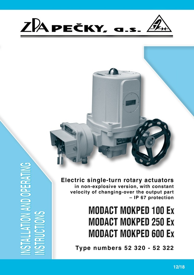
ZPA Pecky, a.s.
ZPA Pecky, a.s. MODACT MOKPED 100 Ex Installation and operating instructions

DNF Controls
DNF Controls ST600-KIPRO user manual

Life
Life RG1 24DL Installation, use and maintenance
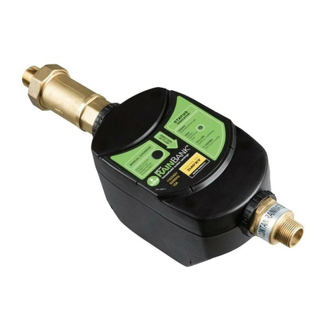
Davey
Davey RainBank KRBS1 installation instructions
