CGC SKC-008 Owner's manual

Installation
Operation
Maintenance
SpaceKeeper Console
Hybrid Heat Pump
SpaceKeeper Console (SKC)
Models: SKC 008-015
REV. 02

Table of Contents
1. INFORMATION................................................................................................................................1
Handling/Storage ..............................................................................................................................1
Weights/Dimensions/Clearances......................................................................................................2
2. INSTALLATION................................................................................................................................3
Delivery Check List ............................................................................................................................3
InstallationProcedure ......................................................................................................................3
3. OPERATION ....................................................................................................................................5
Board Description .............................................................................................................................5
Fan....................................................................................................................................................6
HeatOperation .................................................................................................................................6
Cool Start Up.....................................................................................................................................7
Cool Operation ..................................................................................................................................7
Operational Algorithm.......................................................................................................................9
Thermostat Connections .................................................................................................................10
Shutdown Output ............................................................................................................................10
Fault AlarmOutput ..........................................................................................................................11
4. COMMISSION & START UP.............................................................................................................12
5. MAINTENANCE.............................................................................................................................14
SKC-008 – SKC-015 Wiring Diagram ..................................................................................................16
6. APPENDIXA (SKC-008 – SKC-015 DETAILS)......................................................................................17
Dimensional Diagram: Complete Unit .............................................................................................17
Dimensional Diagram: Chassis ........................................................................................................18
Dimensional Diagram: Piping-and-Receptacle Plate........................................................................19
SpaceKeeper Console: Hose Assembly Connection..........................................................................20

Space Ke e pe r Cons ol e (SKC) – I ns ta l l ati on Opera ti on Ma i ntena nce Ma nua l 1
INFORMATION
Handling
Ca re mus t be ta ken i n ha ndl i ng the Spa ce Kee pe r Cons ol e uni ts a nd othe r a cce s s orie s
to ens ure tha t this e quipme nt does not s usta i n a ny da ma ge . I t i s re comme nde d that
the uni ts be tra n sporte d i ndi vid ua l l y on a two–whe e l ca rt.
The prote cti ve s hi ppi n g pa cka gi ng s houl d rema i n o n the uni t unti l i t is re a dy for
i ns ta l l a ti on . During cons tructi on, th e u ni t mus t not be run a nd sh a l l be s he l te red
from contami na nts a nd de bri s s uch as drywa l l dust, wood chi p s, a nd pa i nt tha t coul d
da ma ge the fa n or bl ock the cool i n g/h ea ti ng coi l whi ch ma y resul t i n di mi ni she d
performa nce .
Storage
The uni t mus t be s tore d i n a n upri ght pos i tion a t al l ti mes .
Fa i lure to ma i ntai n th e u ni t i n a n upri ght pos i ti on ma y res ul t i n pe rmane nt da ma ge
to the un i t. Droppi ng th e uni t or e xpos i ng i t to e xtre me s hock or vi bra tion may a l s o
re s ul t i n pe rma nent da ma ge to the i nte ri or components a nd pi pi ng.
The uni t s ha l l be s tore d i n a non -corros i ve envi ronme nt, s he l tere d from con di ti ons of
e xtre me tempe rature or h umi di ty. Subje cti ng the uni t to cond i tions of thi s nature ma y
re s ul t i n s ign i fi cantl y red uce d pe rfo rma nce , re l i a bi l i ty, and opera ti onal l i fe .
The uni t i s i nte nded for i nte ri or us e onl y a nd s houl d be stored i ndoors a t a l l ti me s to
prote ct i t from the el e me nts a nd to he l p e l imi na te the pote nti al growth of i ndoo r ai r
qual i ty (I AQ) conta mi nants .
If i ndoor stora ge i s not pos s i bl e , the e qui p me nt ma y be s to re d o utdoors duri ng the
s umme r months onl y, i f th e fol l o wi ng p rovi si ons are met:
1. The e qui p me nt mus t be pl a ce d on a dry s u rfa ce , or ra i s e d o ff the ground i n a
ma nne r whi ch a l lo ws for a i r-circul a tion be ne a th the uni t.
2. A wate rproof ta rp mus t b e us ed to cover th e e qui pme nt in orde r to provi de
prote cti on from the e l ements .
3. Conti nuous ventil a ti on to the uni ts mus t be provi ded to he l p pre vent moi s ture
a ccumu l a ti on on the i n te ri or and e xteri or s urfa ce s. Moi s ture bui l du p on, or
wi thi n the u ni t’s i ns ul ati on may re s ul t i n mi crobi al growth tha t ca n l ea d to
odors a nd s e ri ous he a l th-rel ate d I AQ problems .
4. The uni ts mus t be s to red i n the i r o ri gi na l pa cka gi ng.
5. The i ndi vi dua l u ni ts s h al l not be s ta cke d on top of one ano the r.
6. If the uni t wa s pre vi o usl y i n use, e nsure that a l l wa te r has b ee n b l own out and

Space Ke e pe r Cons ol e (SKC) – I ns ta l l ati on Opera ti on Ma i nte na nce Ma nua l 2
INFORMATION
tha t a l l hos e conne cti ons a re pl ugged duri ng s torage.
Weights/Dimensions/Clearances
Weight:
Model
No.
008
010
012
015
We i ght (l b) 160 160 165 175
Unit Dimensions:
Model No.
Uni t Dime ns i ons
(i nche s )
L x W x H
Wa ter Connecti ons
Inlet / Outl e t
(i nche s)
Fi l te r Di me ns i ons
(i nches )
L x W x H
SKC
-
015
48.0 x 12.0 x 25.3
½”
FPT
29.5 x 1.0 x
12.0
SKC-012 48.0 x 12.0 x 25.3 ½” FPT 29.5 x 1.0 x 12.0
SKC
-
010
48.0 x 12.0 x 25.3
½”
FPT
29.5 x 1.0 x 12.0
SKC-008 48.0 x 12.0 x 25.3 ½” FPT 29.5 x 1.0 x 12.0
Se e Appe ndi x A for de ta i l s
Unit Clearances:
Ba ck: N/A
Ri ght: 12.0”
Left: 12.0”
Front: 24.0”
Space Ke e pe r Cons ol e (SKC) – I ns ta l l ati on Opera ti on Ma i nte na nce Ma nua l 3
INSTALLATION
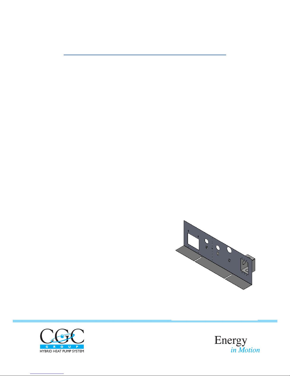
Figure 1: Piping and Receptacle Plate
(See Appendix A for Further Details)
The fol l owi ng i nsta l l a tion p roce dures a re re commende d b y the ma n ufa cturer,
however, it i s the re s pons i bi l ity of the i n s tal l i ng contra ctor to compl y wi th a ll
a ppl i ca bl e code s, l a ws , a nd regul a ti ons of a l l re l eva nt gove rni ng a uthori ti e s ha vi ng
ju ri sdi cti on. Pl eas e re fer to Appe nd i x A for furthe r de ta i l s on the i ns tructi ons
provi de d i n thi s se cti on.
Delivery Checklist
1. Re move packa gi ng a nd i ns pe ct the uni t. Check for s hi ppi ng da ma ge or ma te ri a l
s horta ge ; fi l e a fre i ght cl a i m and noti fy you r s a l e s repre se nta ti ve i f dama ge or
de fici e ncy i s found.
2. Verify th e mode l .
3. Verify th a t the powe r s uppl y compl i es wi th the n a me pl a te s p eci fi ca ti on.
4. Re i ns ta l l ca rd boa rd s l ee ve on uni t to protect during constructi on.
Installation Procedure
1. Thi s he a t pump uni t i s to be i ns ta l l ed wi thin a n i ndoo r envi ronme nt. Lo ca te
the uni t i n a n a rea where the s urroundi ng ai r te mpe ra ture i s a bove 45°F (7°C)
a t all ti mes . Do not a ttempt to l oca te the uni t i n an a rea tha t ma y be
s ubje cte d to fre ezi ng condi ti ons .
2. Determi ne the mou nt l oca ti on of the he a t pump uni t i n accordance with the
cl e ara nce s s pe cifi e d on pa ge 2, a s we l l a s th e l oca ti on of the bui l d i ng’s wa te r
a nd e l e ctrica l s uppl y l i ne s .
3. Pos iti on the pi pi ng-a nd-re ce pta cl e pl a te
(fi gure 1) ove r th e bui l di ng’s sup pl y, re turn,
a nd condens a te fl ui d l ine s . I ns ta l l i sol a ti on
va l ve s o n ea ch of th e pipe s to fa ci l i tate
re mova l a nd s e rvi ci ng of the uni t i n th e
future . Fl us h l i nes p ri or to i ns ta l l a ti on o f
hose s to the bui ldi ng’s s uppl y a nd return
l i nes .
4. The e l e ctrica l outl e t i s supp l i ed a nd
preins ta l l ed i n the des igna te d ca vi ty th a t i s
i nclude d as pa rt of the pi pi n g-a n d-rece pta cl e
pl a te . The e l ectrici a n mus t ta ke ou t the outl e t a nd re i ns ta l l a fter wi ri ng.
5. Wi th the el e ctri cal conne cti on comp le te , u se
me cha ni cal fa s teners to a ffi x the pi pi ng-a nd-

Space Ke e pe r Cons ol e (SKC) – I ns ta l l ati on Opera ti on Ma i nte na nce Ma nua l 4
INSTALLATION
re cepta cl e pl a te to the fl oor, throu gh the two mounti ng sl ots found on the
l owe r l i p of the pl a te .
6. Fi rml y gra sp the front pane l cove r o f the cons ol e and re move i t by l i fti ng i t u p
a nd a wa y from the he a t pump uni t.
7. Wi th the front pane l cover removed, loca te the three fl ui d hos es tha t are
a ttache d to th e uni t’s s uppl y, re turn, a nd conde ns ate connecti ons . Ca re ful l y
remove thes e hoses . The s uppl y a nd re turn hos e s ha ve swi ve l conne ctors .
The condens a te hos e has a hos e cl a mp.
8. Pe rma ne ntl y a ffi x th e threa de d e nd of the suppl y and re turn h os e s (NOT the
s wi ve l conne ctor) to the bui l ding’s s uppl y and re turn l i nes whi ch p rotrude
through the pi p i ng-a n d-re ce pta cl e pla te . Sl id e conde ns ate hos e ove r
conde ns a te l i n e a nd a tta ch with hose cl a mp s u ppl i e d.
9. Pos iti on the he a t pump uni t a ga i n s t the wal l a nd ove r the pi pi ng-a nd-
re cepta cl e pl a te . Ma ke s ure to ce nte r the u ni t a l o ng th e ce nte r-l i n e ma rker
which i s e ngra ve d i n to the pl ate .
10. The th re e hos e s th a t have be en a ffi xe d to the bui ld i ng’s s uppl y, re turn, a nd
conde ns a te p i pi ng s houl d a t thi s point be acce s s ibl e thro ugh the bo ttom of
the hea t pump uni t. Us ing the s wi ve l connectors , re -connect the s upply a nd
return hoses to the a ppropri a te l oca ti ons on the he a t pump unit. Attach
conde ns a te h os e to drai n pa n of un i t a nd atta ch wi th hos e cl a mp provi de d.
11. Ne xt a ffi x the he at pump uni t to the ba ck wal l through the mounti n g hol es
us i ng a ppropri a te l y s i zed s crews . A scre wdri ver e xtens i on ma y be re qui re d i n
order to work a roun d the fa n. For pl ate s wi th fre s h a i r dampe r opti on co nne ct
the two wires wi th s pa de te rmi na l s from the uni t to the da mper te rmina l s .
12. I f furthe r support i s ne ce s s a ry, two a ddi ti ona l mounti ng hol e s ca n be
a cces s e d by re movi ng the uni t’s ca bi net cove r. I n orde r to unfa ste n this
cover, two s cre ws – on e l oca ted on each s i de of the uni t – mus t be re mo ve d.
The two a ddi ti ona l mounti ng hol e s wi l l be l oca te d i n the top l eft a nd ri ght
corne rs .
13. Conne ct the room te mpera ture s e ns or to the el e ctri ca l pane l a s i ndi cate d on
the wi ri ng di a gram. Pl u g the uni t’s e lectri cal cord into the s u pply outl et tha t
i s l oca te d be hi n d th e uni t.
14. Re -atta ch th e he at p ump uni t’s ca bi net cover (i f a ppl i ca bl e ), a nd front
pa nel cover. Ins tal l a ti on of the un i t is now compl ete.

Space Ke e pe r Cons ol e (SKC) – I ns ta l l ati on Opera ti on Ma i nte na nce Ma nua l 5
OPERATION
CAUTION:
To avo i d foul e d ma ch i ne ry, e xte ns i ve u ni t cle a n up, a n d voi d warra nty, do not op erate
uni ts wi th ou t a i r fi l te rs i n pl a ce , a nd do not ope rate uni ts duri ng the cons tructi on
phas e .
The CGC Group Hybri d Hea t Pump p rovi de s ye a r round cool i ng a nd he ati ng a s
control l e d b y the uni t the rmosta t, or by a dire ct d i gi ta l control l er.
The Hyb ri d Hea t Pump provi des cool in g wi th a wa te r-cooled re fri ge ra tion ci rcui t, a nd
provi de s he a ti ng us i ng a hyd roni c coil . The comp res s or ope ra tes i n the cool ing mode
onl y a nd sh uts down duri ng the he a ti n g mode - provi d i ng for qui ete r ope ra ti on,
extende d compres s or l ife, a nd a reduction in energy consumption.
To en s ure corre ct operati on , centra l i ze d e qui pme nt l oca te d wi thi n the bui l di ng
me cha ni cal room i s co nfi gure d to a utoma ti ca l l y provi de e a ch he a t pu mp wi th wa ter
a t the a ppropri a te te mpe ra ture .
Board Description
The uni t’s e l ectroni c ci rcui t boa rd i ncorporate s s i x re l a y outputs wi th the fol lo wi ng
fun cti ons :
K1 – Auxi l i a ry re l a y for cool ing va l ve o n a two-val ve uni t, or he a t va lve on a
de humi di fi cati on uni t.
K2 – Hea ti n g Re l a y
K3 – Al arm Rel a y
K4 – Compre s sor Rela y
K5 – Low Fa n or Fa n Re l a y for b el t dri ve uni ts
K6 – Hi gh Fa n or Compre s s or #2 on b el t dri ve uni ts
Ea ch of thes e rela ys a re conne cte d in pa ral l el to a green LED indi ca to r tha t l i ghts up
when the re l a y i s e ne rgi ze d.
The ci rcui t b oa rd i n corpora tes di gi tal i nputs tha t are opto-coupl e d to a 24V AC s ource .
Thes e ha ve a mb er LED indi ca tors l ocate d nea r the i nput l oca ti ons which are lit whenthe
i nput i s cl os e d. The i nputs i ncl ude:
Hi gh Pre s s ure Swi tch
Low Pres s ure Swi tch
He a t Cal l (W on th ermos ta t te rmi na l )
Cool Cal l (Y on th ermos ta t te rmi nal )

Space Ke e pe r Cons ol e (SKC) – I ns ta l l ati on Opera ti on Ma i nte na nce Ma nua l 6
OPERATION
Fa n Ca ll (G on the rmos ta t te rmi nal )
Au xi l i ary (A on the rmos ta t te rmi nal )
Compres s o r s hutdown (24V AC s i gn a l th ru O/O). Provi di ng a co nti n uous 24V
potentia l to O/O wi l l te rmi na te a nd pre ve nt co mpre s sor o pera ti on. Thi s ca n be
us e d for duty-cycl i ng, mi ni mi zi ng powe r cons umpti on duri ng a n e me rgency power
peri od, or duri ng s uffi ci e ntl y l ow o utd oor a i r tempe ratures whi ch al l ow for free
cool i n g – a l l whi l e ma i nta ini ng the he a ti n g functi on .
Uni t s hutdown (24V AC s i gna l thru A/O). Provi di ng a con ti nu ou s 24V AC pote nti a l to
A/O wi ll te rmina te and preve nt u ni t opera ti on. Thi s can be us e d for a ni ght
shutdown. On both arra ngeme nts a s i ngl e 24V AC s i gna l ca n s hutdown many units .
¼ VA i s requi red pe r uni t.
Fi nal l y, the boa rd ha s fou r a na l og inpu ts whi ch ca n re ce i ve si gna l s vi a thermi s tors .
Thes e i nputs a re a s fol lo ws :
Ta – D i sch a rge Ai r Tempe rature
Tr – Re fri gera nt Te mpe ra ture
Tw – Outgoi ng Wa ter Te mpera ture
Co – Conde ns ate Level
Ta , Tr, And Tw a re 10k Ohm NTP the rmi s to rs , whi l e Co i s a 100 Ohm NTP th ermi s tor.
Thes e i nputs d o not ha ve LED i ndi ca tors .
Fan
1. A fan ca l l on “G” of the thermos ta t termi na l s tri p acti va tes re l a y K5 a nd ca us es
the fa n to o pe ra te a t l ow-s p eed on mul ti -s pe e d uni ts .
2. A hea t ca l l on “W” of the the rmos ta t termi na l s tri p wi l l al s o ca us e the fa n to
opera te a t l ow-s pe ed. If the hea ti ng ca l l i s s ti l l pre s e nt afte r a 10 mi nute
pe riod, mul ti -s pee d u nits wi l l s wi tch th e fan to high-s peed throu gh the
a ctiva ti on of re l ay K6.
3. A cool i ng ca l l on “Y” of th e thermos tat te rmina l s tri p wi l l ca us e the fa n on
multi -s peed uni ts to i mme di ate l y s tep up to hi gh -s p ee d through re l a y K6.
4. Fa n ope ra ti on i s te rmi na te d when a ll ca l l s a re droppe d.
5. When the fa n i s opera ting a t hi gh s pe ed, both rel ays a re e ne rgize d a long with
the ir a s s oci a ted LED i ndi ca tors.
Heat Operation
A cal l o n “W” for h ea t wi l l a ctiva te the fa n at l ow spe ed. I t wi l l al s o
s i mul ta neous l y ene rgi ze the he a t re la y K2 and i ts a s s ocia te d LED. The rel a y K2
wi l l provi de 24V AC fus ed power d i re ctl y to the he at va l ve.

Space Ke e pe r Cons ol e (SKC) – I ns ta l l ati on Opera ti on Ma i nte na nce Ma nua l 7
OPERATION
Cool Start Up
A cal l o n “Y” for cool i n g i ni ti a te s a s eri e s of ch ecks pri or to the s ta rt up of the
compre s s or. The se checks i nclude :
a. Powe r ON ti me r – Compre s s or opera ti on i s de l a ye d for a pproxi ma te l y 5
mi nute s a fte r re stora ti on of p ower. Thi s preve nts al l uni ts from comi ng
on-li ne a t the s a me ti me wh en power i s re stored. I t a l s o pre ve nts
comp re s s or jo l ti ng i n i ns ta nces o f i nte rmi tte nt powe r.
b. An ti-Re cycl e ti mer – There i s a 5-mi nute a nti -recycl e d el ay ti me r tha t
a l l ows th e re fri gera ti on cycl e to a chi eve pres s u re e qu a l iza ti on s o tha t
the compres s or i s unl oade d upon s tart up.
c. Hi gh Pres sure Swi tch – The hi gh re fri ge ra nt p re s s ure s wi tch must be
cl osed pri or to s ta rt up. LED 11 wi l l b e ON. Hi gh pres s ure s wi tch op ens a t
600 ± 10 psi a nd cl os e s at 450 ± 10 ps i.
d. Low Pre s s ure Switch – The l ow pres s ure s witch opera te s pri ma ri l y a s a
l os s of charge protector. I t must be clos e d for compres s or s ta rt up a nd
i ts LED 12 wi l l b e ON. Upon s tart u p, the s i gna l from th e low pres s ure
s wi tch i s i gnored for 5 mi nutes. I n s ome s i tua ti ons, pa rticul a rl y when
the uni t i s col d, th e pre ss ure swi tch wi l l open du ring s tart-up. If the
s wi tch d oes not cl os e wi thi n the 5 mi n ute ignore pe ri od, th e compre s sor
wi l l i mme di a te l y b e turne d off. Low pre s s ure s wi tch opens a t 60 ± 3 psi
a nd cl os e s a t 90 ± 3 ps i .
e. Ai r te mpe ra ture sens or Ta – Sens or Ta wi l l pre ve nt compre s s or s ta rt-up
i f the a i r flowi ng through the uni t i s bel ow 55F. The s e nsor wi ll a l s o
preve nt the compres s or s ta rtup or di sconti nue compre s s or ope ra ti on if
the a i r tempe ra ture i s above 140F a nd wi l l re s e t at 135F. A fl as h code
of 4 wi l l be i ni ti ate d on th e red d i a gnos ti c LED 15.
f. Wa te r te mpera ture s e nsor Tw – Sensor Tw wil l prevent compress or s tart-
up and tri p a n a la rm (a fl a s h code of 3) i f the outgo i ng fl ui d te mpera ture
i s above 125F a nd wi l l re s et the a l a rm a t 120F. The s e ns or wi ll a l s o
tri p a t s ta rtup a nd duri ng ope ra ti on if the wa te r tempe rature i s be l ow
55F a nd wi l l re se t a t 60F.
g. Re fri gera nt tempe ra ture s e ns or Tr – Sens or Tr wi ll pre vent compres s or
s ta rt-up i f the co il te mpe ra ture i s b elow 40F a nd re s e ts a t 65ᵒF. A fl as h
code o f 2 wi l l be i ni ti a ted on th e red di a gnos ti c LED 15.
An y of the a bove fa ul ts wi l l be i n di ca ted vi a the di a gnos ti c LED a nd th e
a ppropri a te di a gnos ti c fl a s h code. Plea s e note the te mpera tures provided
mi gh t va ry b y ±5F.

Space Ke e pe r Cons ol e (SKC) – I ns ta l l ati on Opera ti on Ma i nte na nce Ma nua l 8
OPERATION
Cool Operation
Moni tori ng of th e re fri gera nt cycl e conti nues d uri ng o pe ra ti on of the
comp re s s or. The fol l owing mal functi ons wi ll ca us e the comp re ss or to
s hutdown:
a. If the hea d pre s sure e xce eds the s e t poi nt of the hi gh pre s s ure s wi tch,
the s wi tch wi l l ope n a nd the control bo a rd wi l l te rmi na te compre s s or
opera ti on wi thi n 10 s e cond s . At thi s ti me a fl a s h code of 6 wi l l be
i ni tia te d on the re d d i agnos ti c LED 15. Compre s s or o pe rati on wi l l be
re s to re d i n a ccorda nce wi th the “I ntel l i gent Res e t Al gori th m” (se e
be l ow).
b. If the s uction pres s ure drops be l ow the s e t poi nt of the low pres s ure
s wi tch, the s wi tch wi l l open; i f i t rema i ns o pe n beyond the 5 minute
i gnore pe ri od whi ch i s ini ti a ted upon s ta rt up, compres s or ope ra ti on
wi l l be te rmi na ted wi thi n 10 se con ds. Compres s o r operati on wil l be
re s to re d i n a ccorda nce wi th the “I ntel l i gent Res e t Al gori th m”. A fl a s h
code o f 5 on the re d di agnos ti c LED wi l l b e in i ti a ted a t thi s ti me.
c. Intel l i ge nt Re s et Al gorithm – If a l ow or hi gh pre s sure s wi tch ope ns a nd
re ma i ns open for more tha n 10 mi nute s , a ha rd l ockout wi l l b e i ni ti a ted
a nd the cool i ng mode wi l l be locke d off unti l th e controls a re ma nua ll y
re s et. At the s a me ti me the fa ul t re l ay K3 wil l be se t to a la rm; howe ver,
i f the op en s wi tch cl os es wi thi n 10 mi nutes, a re s ta rt cycle i s i ni ti a te d.
The re s ta rt cycl e begi ns wi th a 10 mi nute del a y a fte r whi ch i f the re i s a
cool ca l l i n pl a ce a nd a ll othe r e na blers a re wi thi n the sta rt para meters ,
the compres s or wi l l a gai n be put i n to o pe rati on. Sh oul d e i the r of the
press ure swi tches ope n a ga i n, the s hutdown p rocedure wi l l cycl e a ga in,
fol l owe d by a resta rt. The i ntel l i ge nt re s e t al go ri thm wi ll a l l o w two
open s wi tch s hutd own s a nd res ta rts wi th i n a 24 hour peri o d - a thi rd
s hutdown wi thi n 24 hours wi l l put the re fri ge ra ti on s ys tem i nto a ful l
a nd ha rd lockout, requiri ng a power down to re s et. I f two or l e ss ope n
s wi tch s hutdowns occur wi th i n a 24 hou r p eri od , the y wi ll be e ra s e d
from me mory a nd wi l l not contri bute to a future hard l ockout. (A ha rd
l ocko ut wil l pre vent compres s or ope ra ti on unti l the contro l s a re
powered down for a t l east 20 seconds a nd the gree n powe r l ight goes
out. A s oft l ockout i s a compres s or s hutdown tha t wi ll be res tore d once
the condi tion ca us i ng the s hutd own returns to norma l .)
d. During compre s s or opera ti on, re fri gera nt tempe rature, s ys te m fl ui d
te mpe ra ture, a nd di s charge a ir tempe ra ture a re continuous l y
moni tored. I f th e refrigerant temperature d rops be l ow 40F, compres s or
opera ti on wi l l be di s a bl e d. After 10 mi nutes , a n au to re set occurs a nd
the compres s or wi ll be e na bl ed a s s oon a s the te mpe ra ture ri se s a bove
65F. Actual compre s s or re s ta rt wi l l be de l aye d a mi ni mum of 5 mi n utes

Space Ke e pe r Cons ol e (SKC) – I ns ta l l ati on Opera ti on Ma i nte na nce Ma nua l 9
OPERATION
by the a n ti-re cycle ti mer. A fl a sh code of 2 wi l l b e i n i ti a ted upon a l ow
refrigera nt te mpera ture s hutdown.
e. If the outgoing system fluid temperature ri s e s a bove 140F, compres s or
opera ti on wi l l be di s a bl e d. The compres s or wi l l be e na bl e d a s s oon as
the tempera ture drops bel ow 120F. The ou tgoi ng s ys te m fl ui d se ns o r i s
mounted on the le a vi ng fl ui d pi pe . Actua l compre ss or res ta rt wi l l b e
de l ayed a mi n i mum of 5 mi n ute s by the a nti -recycl e ti mer. A fl as h code
of 3 wi l l be i ni ti ate d upon a high outgoi n g sys te m fl ui d te mpe ratu re
s hutdown.
f. If the discharge air temperature drops be l ow 40F, compre ss or opera ti on
wi l l be di sa bl e d. The compress or wi ll be e na bl e d a s s oon a s the
te mpe ra ture ri s es a bove 55F. The d i sch a rge a i r tempe rature s ens or i s
mounted on the fa n hous i n g. Actua l compres s or res ta rt wi l l b e de l a yed
a mi ni mum of 5 mi nute s by th e a nti -re cycl e ti mer. A fl a s h code of 4 wi ll
be ini ti a ted upon a l ow d i s charge a i r te mpera ture s h utdown.
g. The condens a te level s ens or is a 100 ohm thermi stor that i s he ated for
15 se conds e very 4 mi nute s ; i ts te mpera ture i s mea s ure d a t th e
be gi n ni ng a nd end of thi s he ati ng cycl e . If the conde ns a te l e vel ri s e s
a bove the s e ns or, i t wi l l n ot wa rm up duri ng th e he a ti ng cycl e , and the
te mp era ture cha nge wi ll be i ns i gni fica nt. It i s thi s l a ck of te mpera ture
cha nge that th e control le r s e es a s a n i mpe ndi n g condens a te ove rfl ow.
When a h igh con de ns a te l e vel i s d ete cte d, comp res s or ope ra ti on i s
i mmedi a tel y te rmi na te d, a nd at the sa me time th e fa n i s s topped fo r 30
s e cond s , and then re s tarte d. At th i s ti me a fl a s h code of 7 wi l l be
i ni tia te d. The 4 mi nute cycl e wi l l co nti nue unti l the cool ing ca l l i s n o
l onge r i n pl a ce . If the condensa te l e ve l drops be l ow the s e ns or,
comp re s s or ope rati on wi l l be re turned to norma l . Ho weve r, i f the
conde ns a te l e ve l s ta ys a bove the s e ns or for more tha n 15 mi nutes , the
fa ult a l a rm wi l l be tri gge re d. Thi s fa ul t s i gna l wi l l a utoma ti ca l ly be
res et once the conde ns ate l eve l goes be l ow the s ens or.
Note: Th e la s t fl as h code wi l l be ma inta i ned i n me mory for one we ek or u ntil the uni t
control s a re powere d d own. The fl a sh code wi l l conti nue unti l the probl e m ha s cleared
a nd the comp re s sor ha s be e n put i nto op era ti on. If a cool i ng cal l i s i n pl a ce , i t mustbe
di s enga ged be fore th e ca u s e of the la s t a l arm s hutdown ca n be i de nti fi e d.
Operation Algorithm
There a re se ve ra l control a l gori thms to preve nt cycl i ng a nd p robl e ma ti c operation.These
a re:
1. Doubl e Cal l – I f th e thermos tat connecti on or s e t up i s i ncorre ct re s ul ti ng i n a
s i mul ta neous ca ll for both he ati ng and cool i ng, the uni t wi l l not ope rate . Thi s

Space Ke e pe r Cons ol e (SKC) – I ns ta l l ati on Opera ti on Ma i nte na nce Ma nua l 10
OPERATION
condi ti on ca n be obs e rve d o n th e thermos tat conne cti on LEDs . (Note : A he a t
pump the rmos ta t ma y caus e thi s s cena ri o).
2. Re vers e Cycl e Ca ll – Poorl y l ocate d a utoma tic cha nge over the rmos ta ts (i e .
the rmos tats mounte d on a wal l oppos i te a di s charge gril l , or a the rmos ta t i n a
doorwa y to ou ts i de) ca n tri gger h ea ting a n d co ol i ng mode cha nge s many ti mes
a n hour. The CGC control l er h as a 10-mi nute a nti -mo de cha nge ti mer whe n
cha ngi ng from cool i ng to he a ting op era ti on. The control le r wi l l not a cce pt a
cha nge i n mo de unti l 10 mi nute s h a ve e l a ps e d s i nce te rmi n a ti on of the
oppos i te ca l l .
Thermostat Connections
The CGC control boa rd ha s bee n des i gned to opera te wi th mos t sta ndard 24V AC
the rmos tats . Thes e thermos tats a re powe re d di rectl y from the CGC boa rd a nd provide
s i gna ls to the a ppropria te te rmi na l s depe ndi ng on the opera ti on a t ha nd - Hea t (W),
Cool (Y), Fan (G) or Aux (A). Whi l e most prese nt-day the rmos ta ts a re compa ti ble withthe
CGC control boa rd, there a re othe rs tha t ma y not work properl y. The foll owi ng shouldbe
che cked for s a ti sfa ctory pe rfo rma nce pri or to i ns tal l a ti on:
1. He at Pump Thermos tat – Some hea t pump units do not have heat rel a ys
(there fore a re not compa ti bl e wi th s ta nda rd the rmos ta ts) a nd re qui re “Hea t
Pump The rmos ta ts ”. Thes e thermos tats ca l l for both hea ti ng a nd cool ing on
one o f the s i gna l wi res . The s e thermos ta ts a re compl e tel y i ncompa ti bl e wi th
CGC’s contro l l er.
2. Me rcury bul b the rmos tat - Thi s type is prob le ma ti c but can be us e d.
Unfortu na te l y, the a nti ci pa tors a re a p robl em. He at a n ti ci pa tors mus t b e i n
s e rie s wi th a h i gh cu rrent rel ay or va lve to functi on, s o do n ot pe rform on a n
e l ectroni c ci rcui t. Thi s wi l l re s ul t i n l arge r tha n norma l tempe rature s wi n gs .
The cool anti ci pator, i f ove rs i ze d, ca n bl e ed e nou gh cu rrent to indi ca te a
cooli ng ca ll e ve n a fte r it ha s be en termi na te d.
3. Ba tte ry powe red the rmos ta ts – The s e the rmos ta ts we re devel ope d a s
re pla ce men ts for ol d mercury bul b the rmos ta ts that ha d 4 wi re co nne cti ons
whil e 24V e l ectroni c th ermos tats re qui re d 5 wi re s. Thes e wi l l work with a CGC
board, a l though CGC does not re comme nd the m. They re qu i re peri odi c ba tte ry
re pla ce men t, which i s some thi ng th at s h oul d b e avoi de d i f poss i b l e.
4. Powe r s teal i ng the rmosta ts – Thi s type of the rmosta t i s el ectroni c a nd wa s
a l s o d evelope d as a re pl a ce me nt for o l d mercury bul b the rmos ta ts . Thes e too
a re probl ema ti c in tha t the y blee d a sma l l amount of curre nt down the s i gn al
wi res a nd thi s may be i nte rpreted a s a s i gna l for he a t or cool .
5. Tri ac s wi tch ed control l ers – Thi s i s a commonl y u se d s witchi ng de vi ce a n d a ll
control l e rs te s te d to date ha ve function ed fl a wl e ss l y. CGC re comme nds th a t

Space Ke e pe r Cons ol e (SKC) – I ns ta l l ati on Opera ti on Ma i nte na nce Ma nua l 11
OPERATION
pri or to i nsta l l a tion of a thi rd pa rty suppl i ed control l e r, it be che cke d for
comp a ti bi li ty. CGC ca n confi rm thi s .
6. Re l ay s wi tche d con trol l ers – Thi s type o f control l e r works we l l wi th CGC
device s .
Shutdown Output
The CGC boa rd has a n opti ona l i n put termi na l s tri p tha t al l ows for two type s of remote
s hutdown. The s e a re: a ) compre s s or s hutdown a nd b) unit s hutdown.
The a dva nta ge of the s e i nputs i s that ma ny uni ts ca n be connecte d in pa rallel and when
powere d by a n i nde pende nt 24V AC s i gna l one or both of the s e a cti ons ca n be
i mpl e me nte d. Common us e s are :
a) Duty cycl i ng for dema nd control
b) Gl o ba l ni ght s e tba ck
c) He ati ng o nl y mode durin g e merge ncy powe r pe ri ods
The CGC controll e r i s a l s o se t up s o thes e s hutdown fun cti ons ca n be i ni ti a te d
i ndivi dua ll y wi th on boa rd 24V powe r. Thi s ca pa bi l i ty a l l ows uni t o r compre s sor
s hutdown ba s e d on a doo r s wi tch, a l i ght swi tch, or occupa ncy s wi tch. A s e pa ra te 24V
power s uppl y i s re qui red i f two or more units a re be i ng shutdown.
Fault Alarm Output
The CGC boa rd i s provi de d wi th a fa ul t a l a rm i ndi ca tor a nd output. Th e fa ul t al a rm
re l ay provides norma l l y ope n and norma l l y cl os e d conta cts for us e i n tra ns mi tti ng
fa ult conditi ons .
NOTE: The fa ul t al a rm i s e ne rgi ze d for NORMAL, a nd de -energi zed for fa ul t. As s uch, i f
the uni t i s not powe red, i f the boa rd fus e i s bl own, or i f the e l ectroni cs a re da ma ged,
a faul t condi ti on wi l l be i ndi cate d.
The fa ul t re l a y i s pa ra l lel e d wi th th e Fa ul t LED whi ch wi ll be ON whe n no fa ul t
condi ti on exi s ts .
Some fa ult co nditi on s incl ude:
a . Ha rd l ockout due to hi gh or l ow pres sure s wi tch bei ng ope n for 10 mi nute s or
l onge r.
b. Ha rd l ockout du e to three h i gh or l ow pre s sure s h utdowns i n a 24 hour p eri od.
c. Hi gh l e vel conde ns a te for a peri od i n e xce ss of 15 mi nu tes .

Space Ke e pe r Cons ol e (SKC) – I ns ta l l ati on Opera ti on Ma i nte na nce Ma nua l 12
COMMISSION & START UP
System Flushing:
Prope r s ys te m cl ea ni ng a n d fl us hi ng i s a n i mportant a s pe ct of the commi s s i oni ng
a nd s ta rt up proce dure for hybrid units . Ens ure the s ys te m ha s be en flus hed properl y.
Thi s prevents foul i ng of the u ni t’s h ea t e xcha nge rs.
NOTE: Hydroni c coi l s a re not 100% d rai na bl e.
System Fluid:
Ens ure that s ys tem wa ter te mpera ture i s withi n a n a ccepta bl e ra nge to fa ci lita te s ta rt
up fo r co oli ng (80-120°F) a nd for he a ti ng (100 – 140°F).
System Water pH:
Sys te m water s houl d have a neutra l pH ba l ance of a p proxi ma tel y 7.5 whi ch wi l l
e xtend the l ife of the hos es , hea t e xcha ngers , a nd other wa ter side a cce s s ori es .
Water Flow Rate:
Op en a l l i sol a ti on va l ves to the un i t. Wi th the uni t i n opera ti on, e ns ure tha t the
e nteri ng and l e a vi ng fl ui d tempe ra ture s a re a ccepta bl e . The re is typi ca l l y a n 8 to 12
de gre e drop or ri se i n temp erature , dependi ng on wh ethe r the uni t i s i n he ati n g or
cooli ng. Unde r e xtre me condi ti on s , sl i ght vari a nces i n the te mpe ra ture ma y be noted .
Freeze Protection from Water System:
Ens ure that fre e ze protecti on is provide d for the outdoo r porti on of the l oo p wa te r
s ys te m. Ina dequa te free ze prote cti on ca n le a d to coi l dama ge.
NOTE: A potenti a l i s s ue ma y a ri s e duri ng cons tructi on where the s ys tem fl ui d l oop is
dra in ed a fter b eing cl e ane d, flus hed, a nd tes te d. Hyb ri d verti cal s ta ck uni ts wi l l not
comp l ete l y dra i n a nd ma y hol d fl ui d i n the conde ns e r or h ea ti ng coi l . Exte nsi ve
da ma ge ma y re s ul t to i nte rna l compone nts i f the sys te m fl ui d fre e ze s a s a res ul t o f
i na dequa te gl ycol b ei ng p re s ent.
Remove Air from System Fluid Loop:

Space Ke e pe r Cons ol e (SKC) – I ns ta l l ati on Opera ti on Ma i nte na nce Ma nua l 13
COMMISSION & START UP
Ai r in the sys te m i mpa i rs uni t ope ra ti on a nd ca n ca us e eros i on i n the pi pi n g.
Clean Unit Filter:
Confi rm tha t the uni t fi lte r that i s be ing us ed i s cl ea n. A cl e a n fi l te r contri bu te s to th e
prope r opera ti on o f the uni t by e ns uri ng that th ere i s a dequa te a i r fl ow a cross th e
coi l.
Fan Rotation:
Ins pe ct the fa n s ecti on to e ns ure that i t i s cl e a n of a n y debri s and that the fan
rotates free l y.
NOTE: Thi s e qui pme nt i s de s i gne d for i n door i ns tal l a ti on ONLY.

Space Ke e pe r Cons ol e (SKC) – I ns ta l l ati on Opera ti on Ma i nte na nce Ma nua l 14
MAINTENANCE
WARNING:
To prevent i nju ry or de ath due to el e ctri ca l sho ck or co ntact wi th movi ng pa rts,
di s abl e the uni t us i n g the di s connect be fore s e rvici ng.
Inspect Filter:
Es tabl i s h a re gula r ma i nte na nce s chedul e . Cl ea n fi l ter fre qu entl y a n d re pl a ce a s
re qui re d. A va cuum ca n be us ed to cl ea n the fi l te r a s we ll a s the s urface of the co i l.
To re move the fi lte r, l i ft i t up and out of th e re ta i ni ng l i p l oca ted towards the bottom
of the u ni t. Re pl ace the ol d fi lte r b y sl i di n g th e top e dge of a new fi l ter up i nto the
ra ck, the n pus hi ng i t i n b ehi nd the reta i n i ng l i p a t th e botto m of the uni t whe re i t wi l l
drop i n to pl a ce .
Check Fan Motors Annually:
Al l CGC Hybri d Hea t Pumps a re pe rmane ntl y l ubri ca te d whe n s hi ppe d from the fa ctory.
Do not oi l o r l ubri ca te the fa n motors.
Visual Inspection:
Vi s ua l l y i ns pe ct uni ts and gi ve s pe ci al a tte nti on to hos e a s s e mbl i e s . Addre ss a ny
s i gns of deteri orati o n or cra ckin g a nd re pa ir l e a ks i mme di a te l y.
Amperage Check on Compressor and Fan Motor:
Check tha t a l l e l ectri ca l connects a re ti ght. Curre nt dra w on thi s e qui pme nt s hou l d
not e xcee d normal ful l loa d or ra te d l oa d a mps by more tha n 10 pe rcent of the va l ue s
noted o n the uni t na mepl a te .
Safety Control Reset:
Al l CGC hybri d hea t pumps i nclu de h igh a nd l ow pre s s u re s wi tche s to preve nt the uni t
from operati ng under a bno rmal a nd potenti a l l y harmful condi tions . If mul ti pl e
press ure al a rms occur wi th i n a 24-hour pe riod, the compres s o r opera ti on wi ll b e
pe rma ne ntl y l ocke d out unti l the unit i s re se t or powe r i s di s conne cted for 20
s e conds .

Space Ke e pe r Cons ol e (SKC) – I ns ta l l ati on Opera ti on Ma i nte na nce Ma nua l 15
MAINTENANCE
NOTE: If the hea t pump mus t be res e t more th a n twi ce , che ck the uni t fo r a dirty a i r
fi l ter, a bnorma l ente ri ng/l ea ving wa te r tempera ture , i nade quate wa ter fl ow, or
i nterna l ma l functi ons tha t may b e caus i n g hi gh o r l ow pre s s ure cond i ti ons . If the uni t
conti nue s to tri gge r the a l a rm, conta ct a trai ned s ervi ce te chni ci a n a nd e ns ure the
probl e ms are re sol ved be fo re conti nui ng use of the uni t.
Space Ke e pe r Cons ol e (SKC) – I ns ta l l ati on Opera ti on Ma i nte na nce Ma nua l 16
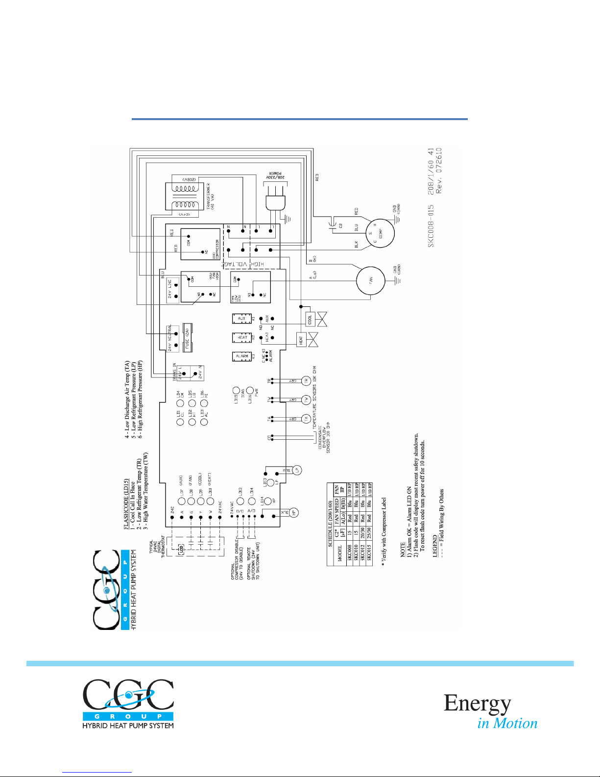
MAINTENANCE – STANDARD WIRING DIAGRAM
Space Ke e pe r Cons ol e (SKC) – I ns ta l l ati on Opera ti on Ma i nte na nce Ma nua l 17
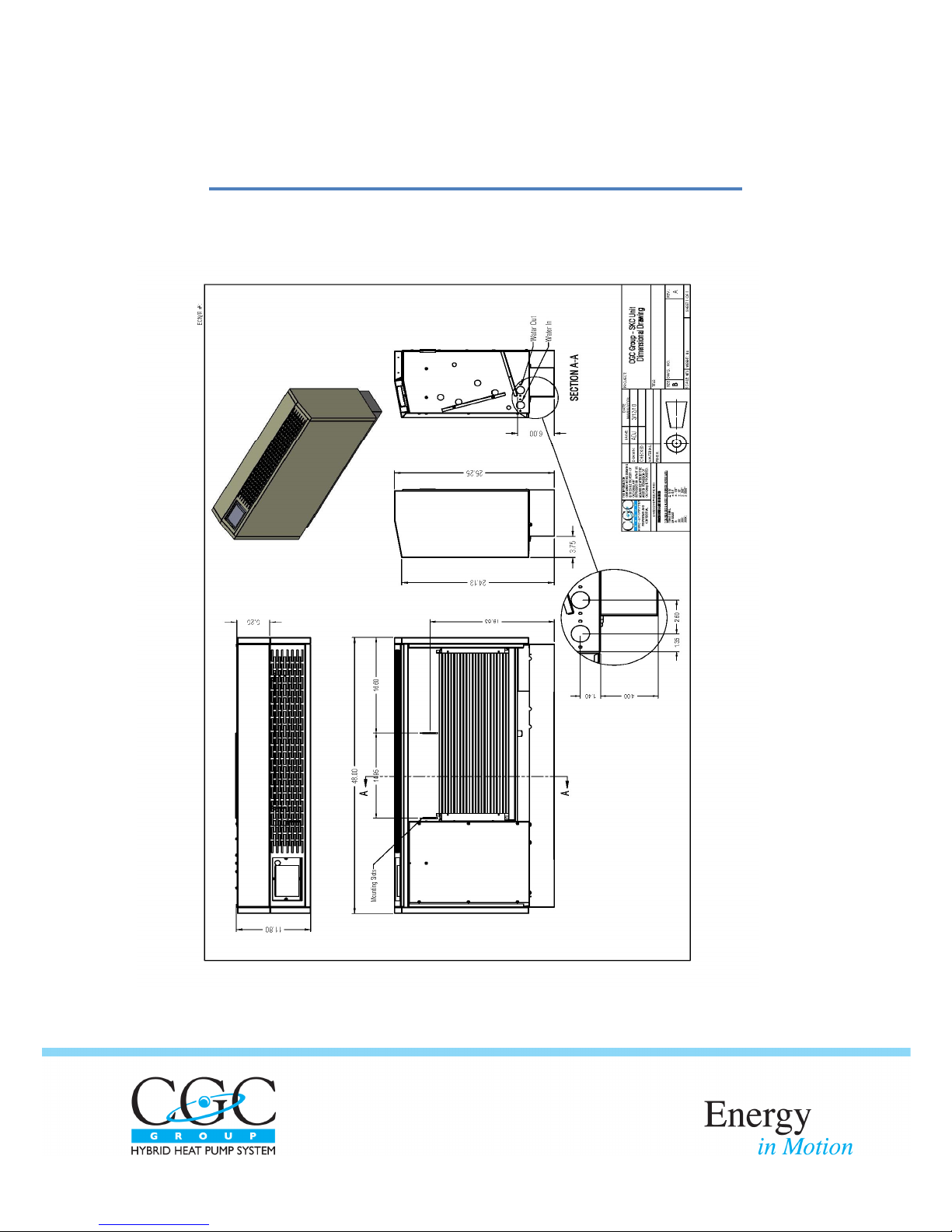
DETAILS
SpaceKeeper Console Dimensional Diagram: Complete Unit
SpaceKeeper Console Dimensional Diagram: Chassis

Space Ke e pe r Cons ol e (SKC) – I ns ta l l ati on Opera ti on Ma i nte na nce Ma nua l 18
DETAILS
Dimensional Diagram: Piping and Receptacle Plate
Note: The fresh air damper mechanism is optional
This manual suits for next models
3
Table of contents
Other CGC Heat Pump manuals


Popular Heat Pump manuals by other brands

GRE
GRE BC3800 instruction manual

Atlantic
Atlantic Alfea Hybrid Duo Series Installation and commissioning instructions

Airwell
Airwell XLM9 Installation and maintenance manual

ICP
ICP PHAD60N1K1 installation instructions

Calorex
Calorex aa300 Technical manual

Daikin
Daikin Altherma EHYKOMB33AA Installation and operation manual

Fujitsu
Fujitsu Waterstage Comfort Series Maintenance Document

poolstar
poolstar POOLEX PICO Installation and user manual

Aquacal
Aquacal 100 Owner's manual and installation guide

Harmopool
Harmopool ZVWX4013 instructions

Hitachi
Hitachi RAS Series instruction manual

STIEBEL ELTRON
STIEBEL ELTRON WPE Installation


