CGC SpaceKeeper SKH008 Owner's manual

July7th,2010
Installation
Operation
Maintenance
HybridHorizontal
HeatPump
Spacekeeper
Models:SKH008–SKH060

July7th,2010
TableofContents
1.INFORMATION.................................................................................................................................1
Handling/Storage..........................................................................................................................................1
Weight/Dimension/Clearances.....................................................................................................................2
2.INSTALLATION..................................................................................................................................3
GeneralInstallChecklist................................................................................................................................5
Location/Placement/Piping..........................................................................................................................6
CondensateDrainConnection......................................................................................................................7
Wiring............................................................................................................................................................8
3.OPERATION......................................................................................................................................9
BoardDescription.......................................................................................................................................10
Fan...............................................................................................................................................................11
HeatOperation...........................................................................................................................................11
CoolStartUp...............................................................................................................................................11
CoolOperation............................................................................................................................................12
OperationalAlgorithm................................................................................................................................14
ThermostatConnection..............................................................................................................................14
ShutdownOutput........................................................................................................................................15
FaultAlarmOutput.....................................................................................................................................15
4.COMMISSION&STARTUP.............................................................................................................17
5.MAINTENANCE...............................................................................................................................20
SKH008‐SKH018WiringDiagram..............................................................................................................21
SKH020‐SKH060WiringDiagram..............................................................................................................22
6.APPENDIXA(DETAILS)...................................................................................................................23
SKH008‐SKH018.........................................................................................................................................24
SKH020‐SKH036.........................................................................................................................................25
SKH042‐SKH060.........................................................................................................................................26

HybridHorizontalSpacekeeper–InstallationOperationMaintenanceManual
INFORMATION
R090303InstallationOperationMaintenanceManualissubjecttochangewithoutnoticePage1
Handling
Caremustbetakeninhandlingthehorizontalunitandotheraccessoriestoensurethatthis
equipmentdoesnotsustainanydamage.
Theprotectiveshippingpackagingshouldremainontheunituntilitisreadyforinstallation.
Duringconstruction,theunitmustnotberunandshallbeshelteredfromcontaminantsand
debrissuchasdrywalldust,woodchips,andpaintthatcoulddamagethefanorblockthe
cooling/heatingcoilwhichmayresultindiminishedperformance.
Storage
Theunitmustbestoredinanuprightpositionatalltimes.
Failuretomaintaintheunitinanuprightpositionmayresultinpermanentdamagetotheunit.
Droppingthechassisorexposingittoextremeshockorvibrationmayalsoresultinpermanent
damagetotheinteriorcomponentsandpiping.
Theunitshouldbestoredinanon‐corrosiveenvironmentshelteredfromconditionsofextreme
temperatureorhumidity.Subjectingtheunittoconditionsofthisnaturemayresultin
significantlyreducedperformance,reliability,andoperationallife.
Theunitisintendedforinterioruseonlyandshouldbestoredindoorsatalltimestoprotectit
fromtheelementsandtohelpeliminatethepotentialgrowthofindoorairquality(IAQ)
contaminants.
Ifindoorstorageisnotpossible,theequipmentmaybestoredoutdoorsduringthesummer
monthsonly,ifthefollowingprovisionsaremet:
1. Theequipmentmustbeplacedonadrysurface,orraisedoffthegroundinamanner
whichallowsforair‐circulationbeneaththeunit.
2. Awaterprooftarpmustbeusedtocovertheequipmentinordertoprovideprotection
fromtheelements.
3. Continuousventilationtotheunitsmustbeprovidedtohelppreventmoisture
accumulationontheinteriorandexteriorsurfaces.Moisturebuildupon,orwithinthe
unit’sinsulationmayresultinmicrobialgrowththatcanleadtoodorsandserious
health‐relatedIAQproblems.
4. Theunitsmustbestoredintheiroriginalpackaging.

HybridHorizontalSpacekeeper–InstallationOperationMaintenanceManual
INFORMATION
R090303InstallationOperationMaintenanceManualissubjecttochangewithoutnoticePage2
5. Theindividualunitsshallnotbestackedontopofoneanother.
6. Iftheunitwaspreviouslyinuse,ensurethatallwaterinthecoilhasbeenblownoutand
thatallhoseconnectionsarepluggedduringstorage.
Weight/Dimensions/Clearances
Weight:
Model008010012015018020024030036042048060
Weight
(lb)130130135150160205235235235375300375
UnitDimensions:
SeeAppendixA‐Details
UnitClearances:
SeeAppendixA‐Details

HybridHorizontalSpacekeeper–InstallationOperationMaintenanceManual
INSTALLATION
R090303InstallationOperationMaintenanceManualissubjecttochangewithoutnoticePage3

HybridHorizontalSpacekeeper–InstallationOperationMaintenanceManual
INSTALLATION
R090303InstallationOperationMaintenanceManualissubjecttochangewithoutnoticePage4
TheInstallationofHybridHorizontalSpaceKeeperunitsandaccessoriesmustbeinaccordance
withlocalcodesandallregulationsofallrelevantgoverningauthoritieshavingjurisdiction.The
followinginstallationproceduresarerecommendedbytheManufacturer.Itisthe
responsibilityoftheinstallingcontractortocomplywithallapplicablecodesandregulations.

HybridHorizontalSpacekeeper–InstallationOperationMaintenanceManual
INSTALLATION
R090303InstallationOperationMaintenanceManualissubjecttochangewithoutnoticePage5
LEFTRETURN
AIRFILTER
ARR.3BACK
SUPPLYAIRARR.1RIGHT
SUPPLYAIR
COMPRESSORAND
CONTROLACCESS
PANEL
DELIVERYANDGENERALINSTALLATIONCHECKLIST
ThelistbelowsummarizesthestepsrequiredtosuccessfullyinstallaCGCHorizontal
SpaceKeeperunit.
1. Removepackagingandinspecttheunit.Checkforshippingdamageormaterial
shortage;fileafreightclaimandnotifyyoursalesrepresentativeifdamageordeficiency
isfound.
2. Verifythemodel.
3. Verifythatthepowersupplycomplieswiththenameplatespecification.
4. Connectproperlysizedandprotectedpowersupplywiringtothedisconnect(not
supplied).
5. Installpropergroundingwirestoanearthground.
Figure1
FRONT
HybridHorizontalSpacekeeper–InstallationOperationMaintenanceManual
INSTALLATION
R090303InstallationOperationMaintenanceManualissubjecttochangewithoutnoticePage6
LOCATION
1. Determinefuturehorizontalmount
locationwithclearancesshownin
appendixA.
2. Locatetheunitinanindoorarea.Theair
temperaturesurroundingandbeing
suppliedtotheunitmustbeabove45°F
(7°C)atalltimes.Donotlocatetheunitin
areassubjecttofreezing.
PLACEMENT
1. Positiontheunitandfastentoceiling
ensuringtheunitisleveled.Extension
Rods(notsuppliedbyCGC)andRubber
isolatorsaretobeused.DONOTblock
accesspanelswithmountingrods.
2. Meetspecifiedclearancestoprovide
roomforremovalofallaccesspanels.
3. Provideaccesstowatervalvesand
fittings,aswellasscrewdriveraccessto
theunitsidepanels,dischargeaircollar,
andallelectricalconnections.
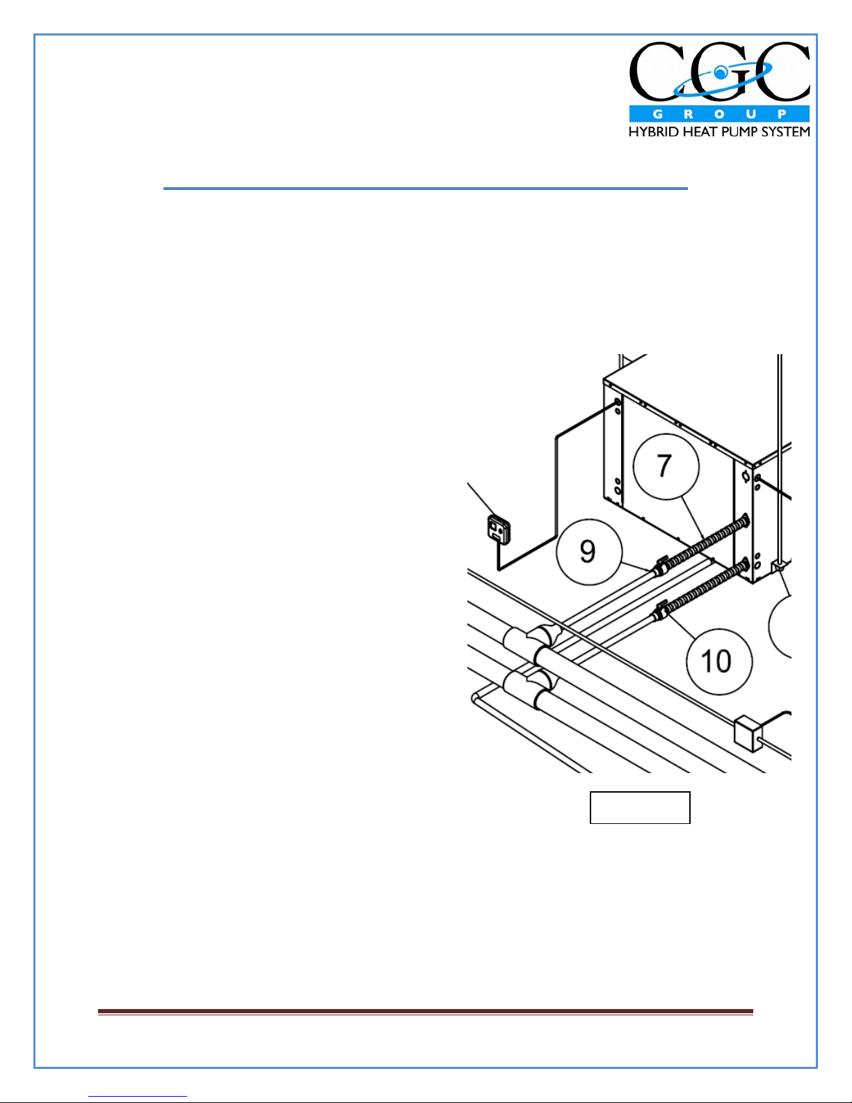
PIPING
CAUTION:Pipingmustcomplywithallapplicable
codesandregulations.
1. Installisolationvalvesateachunittopermit
unitremovalforservicing.
2. DONOTbendorkinksupplylinesorhoses(If
supplied).Supplyandreturnhosesarefitted
withswiveljointfittingsatoneendtoallow
removalforfutureservicing.
Figure2

HybridHorizontalSpacekeeper–InstallationOperationMaintenanceManual
INSTALLATION
R090303InstallationOperationMaintenanceManualissubjecttochangewithoutnoticePage7

HybridHorizontalSpacekeeper–InstallationOperationMaintenanceManual
INSTALLATION
R090303InstallationOperationMaintenanceManualissubjecttochangewithoutnoticePage8
NOTE:Insulationofthewaterpipingloopisnotrequiredexceptwherepipingrunsthrough
unheatedareasorareasontheexteriorofthebuilding.Thenormalloopoperating
temperaturerangeis85°F(29°C)to120°F(49°C).
WIRING
1. Wireroomtemperaturesensortoelectricalpanelasindicatedonthewiringdiagram.
2. Connectpower.

HybridHorizontalSpacekeeper–InstallationOperationMaintenanceManual
OPERATION
R090303InstallationOperationMaintenanceManualissubjecttochangewithoutnoticePage9
CAUTION:
Toavoidfouledmachinery,extensiveunitcleanup,andvoidwarranty,donotoperateunits
withoutairfiltersinplace,anddonotoperateunitsduringtheconstructionprocess.
TheCGCGroupHybridHeatPumpprovidesyearroundcoolingandheatingascontrolledbythe
unitthermostatorbyadirectdigitalcontroller.
TheCGCGrouphybridheatpumpprovidescoolingwithawater‐cooledrefrigerationcircuit,
andprovidesheatingusingahydroniccoil.Thecompressoroperatesinthecoolingmodeonly
andshutsdownduringtheheatingmodeprovidingforquieteroperation,extendedcompressor
life,andareductioninenergyconsumption.
Toensurecorrectoperation,centralizedequipmentlocatedwithinthebuildingmechanical
roomisautomaticallycontrolledtoprovideeachheatpumpunitwithwaterthatisatthe
appropriatetemperature.

HybridHorizontalSpacekeeper–InstallationOperationMaintenanceManual
OPERATION
R090303InstallationOperationMaintenanceManualissubjecttochangewithoutnoticePage10
Theunitcircuitboardincorporatessixrelayoutputswiththefollowingfunctions:
•K1–Auxiliaryrelayforcoolingvalveonatwo‐valveunitorheatvalveonadehumidification
unit.
•K2–HeatingRelay
•K3–AlarmRelay
•K4–CompressorRelay
•K5–LowFanorFanRelayforbeltdriveunits
•K6–HighFanorCompressor#2onbeltdriveunits
Eachoftheserelayshave,inparallel,agreenLEDindicatorthatlightsupwhentherelayis
energized.
Thecircuitboardincorporatesdigitalinputsthatareopto‐coupledtoa24VACsource.Thesehave
amberLEDindicatorslocatedneartheinputlocationswhicharelitwhentheinputisclosed.The
inputsinclude:
•HighPressureSwitch
•LowPressureSwitch
•HeatCall(Wonthermostatterminal)
•CoolCall(Yonthermostatterminal)
•FanCall(Gonthermostatterminal)
•Auxiliary(Aonthermostatterminal)
•Compressorshutdown(24VACsignalthruO/O).Providingacontinuous24Vpotentialto
O/Owillterminateandpreventcompressoroperation.Thiscanbeusedforduty‐cycling,
minimizingpowerconsumptionduringanemergencypowerperiodorduringsufficiently
lowoutdoorairtemperatureswhichallowforfreecooling–allwhilemaintainingthe
heatingfunction.
•Unitshutdown(24VACsignalthruA/O).Providingacontinuous24VACpotentialtoA/Owill
terminateandpreventunitoperation.Thiscanbeusedforanightshutdown.Onboth
arrangementsasingle24VACsignalcanshutdownmanyunits.¼VAisrequiredperunit.
Finally,theboardhasfouranaloginputsprovidedviathermistors.Theseinputsareasfollows:
•Ta–DischargeAirTemperature
•Tr–RefrigerantTemperature
•Tw–OutgoingWaterTemperature
•Co–CondensateLevel
Ta,Tr,AndTware10kOhmNTPthermistors,whileCoisa100OhmNPTthermistor.These
InputsdonothaveLEDindicators.

HybridHorizontalSpacekeeper–InstallationOperationMaintenanceManual
OPERATION
R090303InstallationOperationMaintenanceManualissubjecttochangewithoutnoticePage11
FAN
1. Acallon“G”forfanonthethermostatterminalstripwillcausethefantooperate
continuouslyonlowfanspeedthroughK5onmultispeedunits.
2. Acallon“W”forheatonthethermostatterminalstripwillalsocausethefantooperate
onlowspeed.Iftheheatingcallisstillpresentaftera10minuteperiod,themultispeed
unitswillswitchthefantohighspeedthroughRelayK6.
3. Acallon“Y”forcoolingonthethermostatterminalstripwillcausethefanonmulti‐
speedunitstoimmediatelystepuptohighspeedthroughRelayK6.
4. Fanoperationwillterminatewheneverallcallsaredropped.
5. Whenthefanisoperatingathighspeed,bothrelaysareenergizedalongwiththeir
associatedLEDindicators.
HEATINGOPERATION
1. Acallon“W”forheatwillactivatethefanatlowspeed.Itwillalsosimultaneously
energizetheheatrelayK2anditsassociatedLED.TherelayK2willprovide24VACfused
powerdirectlytotheheatvalve.
COOLSTARTUP
1. Acallon“Y”forcoolinginitiatesaseriesofcheckspriortothestartupofthe
compressor.Thesechecksinclude:
a. PowerONtimer–Compressoroperationisdelayedforapproximately5minutes
afterrestorationofpower.Thispreventsallunitsfromcomingonlineatthe
sametimewhenpowerisrestored.Italsopreventscompressorjoltingwith
intermittentpower.
b. Anti‐Recycletimer–Thereisa5‐minuteanti‐recycledelaytimerthatallowsthe
refrigerationcycletoachievepressureequalizationsothatthecompressoris
unloadeduponstartup.
c. HighPressureSwitch–Thehighrefrigerantpressureswitchmustbeclosedprior
tostart.LED11willbeON.
d. LowPressureSwitch–Thelowpressureswitchoperatesprimarilyasalossof
chargeprotector.ItmustbeclosedforcompressorstartupanditsLED12willbe
ON.Thepressureswitchhasa5minutetimeignoresubsequenttostart‐up.In
somesituations,particularlywhentheunitiscold,thepressureswitchwillopen

HybridHorizontalSpacekeeper–InstallationOperationMaintenanceManual
OPERATION
R090303InstallationOperationMaintenanceManualissubjecttochangewithoutnoticePage12
duringstart‐up.Iftheswitchdoesnotremakewiththe5minuteignoreperiod,
thecompressorwillimmediatelybestopped.
e. AirtemperaturesensorTa–SensorTawillpreventcompressoroperationifthe
airflowingthroughtheunitisbelow60°F(15°C).
f. WatertemperaturesensorTw–SensorTwwillpreventcompressoroperationif
theoutgoingfluidtemperatureisabove140°F(60°C).
g. RefrigeranttemperaturesensorTr–SensorTrwillpreventcompressor
operationifthecoiltemperatureisbelow35°F(2°C).
h. AnyoftheabovefaultswillbeindicatedwiththeDiagnosticCodedescribed
undertheDIAGNOSTICSsection.
COOLOPERATION
1. Monitoringoftherefrigerantcyclecontinuesduringoperationofthecompressor.The
followingmalfunctionswillcausethecompressortoshutdown:
a. Iftheheadpressureexceedsthesetpointofthehighpressureswitch,theswitch
willopenandthecontrolboardwillterminatethecompressoroperationwithin
10seconds.Atthistimeaflashcodeof6willbeinitiatedonthereddiagnostic
LED15.Compressoroperationwillberestoredinaccordancewiththe
“Intelligentreset”algorithm.
b. Ifthesuctionpressuredropsbelowthesetpointofthelowpressureswitch,the
switchwillopenandifitremainsopenbeyondthe5minuteignoreperiodafter
startup,compressoroperationwillbeterminatedwithin10seconds.
Compressoroperationwillberestoredinaccordancewiththe“IntelligentReset”
algorithm.Aflashcodeof5onthereddiagnosticLEDwillbeinitiatedatthis
time.
c. IntelligentResetAlgorithm–Ifaloworhighpressureswitchopensandremains
openformorethan10minutes,ahardlockoutwillbeinitiatedandthecooling
modewillbelockedoffuntilthecontrolsaremanuallyreset.Atthesametime
thefaultrelayK3willbesettoalarm;however,iftheopenswitchcloseswithin
10minutesarestartcycleisinitiated.Therestartcyclebeginswitha10minute
delayafterwhichifthereisacoolcallinplaceandallotherenablersarewithin
thestartparameters,thecompressorwillagainbeputintooperation.Should
eitherofthepressureswitchesopenagain,theshutdownprocedurewillcycle
again,followedbyarestart.Theintelligentresetwillallowtwoopenswitch
shutdownsandrestartsina24hourperiodandathirdshutdownwithin24
hourswillputtherefrigerationsystemintoafullandhardlockout,requiringa

HybridHorizontalSpacekeeper–InstallationOperationMaintenanceManual
OPERATION
R090303InstallationOperationMaintenanceManualissubjecttochangewithoutnoticePage13
powerdowntoreset.Iftwoorlessswitchopenshutdownsoccurwithina24
hourperiod,theywillbeerasedfrommemoryandwillnotcontributetoafuture
hardlockout.(Ahardlockoutwillpreventcompressoroperationuntilthe
controlsarepowereddownforatleast20seconds,andthegreenpowerlight
goesout.Asoftlockoutisacompressorshutdownthatwillberestoredoncethe
conditioncausingtheshutdownreturnstonormal.)
d. Duringcompressoroperation,refrigeranttemperature,systemfluid
temperatureanddischargeairtemperaturearecontinuouslymonitored.Ifthe
refrigeranttemperaturedropsbelow35°F,compressoroperationwillbe
disabled.After10minutesanautoresetoccursandthecompressorwillbe
enabledassoonasthetemperaturerisesabove60°F.Actualcompressorrestart
willbedelayedaminimumof5minutesbytheanti‐recycletimer.Aflashcodeof
2willbeinitiateduponalowrefrigeranttemperatureshutdown.
e. Iftheoutgoingsystemfluidtemperaturerisesabove140°F,compressorstartup
willbedisabled.After10minutesanautoresetoccursandthecompressorwill
beenabledassoonasthetemperaturedropsbelow115°F.Theoutgoingsystem
fluidsensorismountedontheleavingfluidpipe.Actualcompressorrestartwill
bedelayedaminimumof5minutesbytheanti‐recycletimer.Aflashcodeof3
willbeinitiateduponahighoutgoingsystemfluidtemperatureshutdown.
f. Ifthedischargeairtemperaturedropsbelow50°F,compressoroperationwillbe
disabled.After10minutesanautoresetoccursandthecompressorwillbe
enabledassoonasthetemperaturerisesabove60°F.Thedischargeair
temperaturesensorismountedonthefanhousing.Actualcompressorrestart
willbedelayedaminimumof5minutesbytheanti‐recycletimer.Aflashcodeof
4willbeinitiateduponalowdischargeairtemperatureshutdown.
g. Thecondensatelevelsensorisa100ohmthermistorthatisheatedfor15
secondsevery4minutes.Itstemperatureismeasuredatthebeginningofthe
heatcycle,andagainattheendoftheheatingcycle.Ifthecondensatelevelrises
abovethesensoritwillnotwarmupduringthewarmupcycle,andthe
temperaturechangewillbeinsignificant.Itisthislackoftemperaturechange
thatthecontrollerseesasanimpendingcondensateoverflow.Whenhigh
condensatelevelisdetected,compressoroperationisimmediatelyterminated,
andatthesametimethefanisstoppedfor30seconds,andthenrestarted.At
thistimeaflashcodeof7willbeinitiated.The4minutecyclewillcontinueuntil
thecoolingcallisnolongerinplace.Ifthecondensateleveldropsbelowthe
sensor,compressoroperationwillbereturnedtonormal.However,ifthe
condensatelevelstaysabovethesensorformorethan15minutes,thefault

HybridHorizontalSpacekeeper–InstallationOperationMaintenanceManual
OPERATION
R090303InstallationOperationMaintenanceManualissubjecttochangewithoutnoticePage14
alarmwillbetriggered.Thisfaultsignalwillautomaticallyresetoncethe
condensatelevelgoesbelowthesensor.
Note:Thelastflashcodewillbemaintainedinmemoryfor1weekoruntiltheunitcontrolsare
powereddown.Theflashcodewillcontinueuntiltheproblemhasclearedandthecompressorhas
beenputintooperation.Ifacoolingcallisinplace,itmustbedisengagedbeforethecauseofthe
lastalarmshutdowncanbeidentified.
OPERATIONALGORITHM
Thereareseveralcontrolalgorithmstopreventcyclingandproblematicoperation.Theseare:
1. DoubleCall–Ifthermostatconnectionsorsetupisincorrectresultinginasimultaneous
callforbothheatingandcooling,theunitwillnotoperate.Thisconditioncanbe
observedonthethermostatconnectionLEDs.(Note:Aheatpumpthermostatwill
presentthisscenario)
2. ReverseCycleCall–Poorlylocatedautomaticchangeoverthermostats(ie.thermostats
mountedonawalloppositeadischargegrill,orathermostatinadoorwaytooutside)
cantriggerheatingandcoolingmodechangesmanytimesanhour.TheCGCcontroller
hasa10‐minuteanti‐modechangetimerforbothheatingandcoolingmodechanges.
Thecontrollerwillnotacceptachangeinmodeuntil10minuteshaveelapsedsince
terminationoftheoppositecall.
THERMOSTATCONNECTIONS
TheCGCcontrolboardhasbeendesignedtooperatewithmoststandard24VACthermostats.
ThesearepoweredfromtheCGCboardwith24VACandsimplyswitchpowerONtoeachofthe
Heat(W),Cool(Y),Fan(G)orAux(A).Whilemostpresentdaythermostatsoperateinthismanner
thereareothersthatmayormaynotworkproperly.Thefollowingshouldbecheckedoutfor
satisfactoryperformancepriortoinstallation:
1. HeatPumpThermostat–Someheatpumpunitsdonothaveheatrelays(thereforeare
notcompatiblewithstandardthermostats)andrequire“HeatPumpThermostats”.
Thesethermostatscallforbothheatingandcoolingononeofthesignalwires.These
thermostatsarecompletelyincompatiblewithCGC’scontroller.
2. Mercurybulbthermostat‐Thistypeisproblematicbutcanbeused.Unfortunately,the
anticipatorsareaproblem.Heatanticipatorsmustbeinserieswithahighcurrentrelay
orvalvetofunction,sodonotperformonanelectroniccircuit.Thiswillresultinlarger

HybridHorizontalSpacekeeper–InstallationOperationMaintenanceManual
OPERATION
R090303InstallationOperationMaintenanceManualissubjecttochangewithoutnoticePage15
thannormaltemperatureswings.Thecoolanticipator,ifoversized,canbleedenough
currenttoindicateacoolingcallevenafterithasbeenterminated.
3. Batterypoweredthermostats–Thesethermostatsweredevelopedasreplacementsfor
oldmercurybulbthermostatsthathad4wireconnectionswhile24Velectronic
thermostatsrequired5wires.ThesewillworkwithaCGCboard,althoughCGCdoesnot
recommendthem.Theyrequireperiodicbatteryreplacement,whichissomethingthat
shouldbeavoidedifpossible.
4. Powerstealingthermostats–Thistypeofthermostatiselectronicandwasalso
developedasareplacementforoldmercurybulbthermostats.Thesetooare
problematicinthattheybleedasmallamountofcurrentdownthesignalwiresandthis
maybeinterpretedasasignalforheatorcool.
5. Triacswitchedcontrollers–Thisisacommonlyusedswitchingdeviceandallcontrollers
testedtodatehavefunctionedflawlessly.CGCrecommendsthatpriortoinstallationof
athirdpartysuppliedcontroller,itbecheckedforcompatibility.CGCcanconfirmthis.
6. Relayswitchedcontrollers–ThistypeofcontrollerworkswellwithCGCdevices.
SHUTDOWNOUTPUT
TheCGCboardhasanoptionalinputterminalstripthatallowsfortwotypesofremoteshutdown.
Thesearea)compressorshutdownandb)unitshutdown.
Theadvantageoftheseinputsisthatmanyunitscanbeconnectedinparallelandwhenpowered
byanindependent24VACsignaloneorbothoftheseactionscanbeimplemented.Commonuses
are:
a. Dutycyclingfordemandcontrol
b. Globalnightsetback
c. Heatingonlymodeduringemergencypowerperiods
TheCGCcontrollerisalsosetupsotheseshutdownfunctionscanbeinitiatedindividuallywithon
board24Vpower.Thiscapabilityallowsunitorcompressorshutdownbasedonadoorswitch,a
lightswitch,oroccupancyswitch.Aseparate24Vpowersupplyisrequirediftwoormoreunitsare
beingshutdown.
FAULTALARMOUTPUT
TheCGCboardisprovidedwithafaultalarmindicationandoutput.Thefaultalarmrelay
providesnormallyopenandnormallyclosedcontactsforuseintransmittingfaultconditions.
NOTE:ThefaultalarmisenergizedforNORMAL,andde‐energizedforfault.Assuch,iftheunit

HybridHorizontalSpacekeeper–InstallationOperationMaintenanceManual
OPERATION
R090303InstallationOperationMaintenanceManualissubjecttochangewithoutnoticePage16
isnotpowered,iftheboardfuseisblown,oriftheelectronicsaredamaged,afaultcondition
willbeindicated.
ThefaultrelayisparalleledwiththeFaultLEDwhichwillbeONwhennofaultconditionexists.
Otherfaultconditionsare:
d. Hardlockoutduetohighorlowpressureswitchbeingopenfor10minutesorlonger.
e. Hardlockoutduetothreehighorlowpressureshutdownsina24hourperiod.
f. Highlevelcondensateforaperiodinexcessof15minutes.

HybridHorizontalSpackeeper–InstallationOperationMaintenanceManual
COMMISSION&STARTUP
R090303InstallationOperationMaintenanceManualissubjecttochangewithoutnoticePage17
SystemFlushing:
Propersystemcleaningandflushingisanimportantaspectofthecommissioningandstartup
procedureforhybridunits.Ensurethesystemhasbeenflushedproperly.Thispreventsfouling
oftheunit’sheatexchangers.
NOTE:Hydroniccoilsarenot100%drainable.
SystemFluid:
Ensurethatsystemwatertemperatureiswithinanacceptablerangetofacilitatestart‐up(80‐
120°F)forcoolingand(100–140°F)forheating.
SystemWaterpH:
SystemwatershouldhaveaneutralpHbalanceofapproximately7.5whichwillextendthelife
ofthehoses,heatexchangers,andotherwatersideaccessories.
WaterFlowRate:
Openallisolationvalvestotheunit.Ensurethattheenteringandleavingfluidtemperaturesof
thehybridunitinoperationareacceptable.Thereistypicallyan8to12degreedroporrisein
temperature,dependingonwhethertheunitisincoolingorheating.Underextreme
conditions,slightvariancesinthetemperaturemaybenoted.
FreezeProtectionfromWaterSystem:
Ensurethatfreezeprotectionisprovidedfortheoutdoorportionoftheloopwatersystem.
Inadequatefreezeprotectioncanleadtocoildamage.
NOTE:Apotentialissuemayariseduringconstructionwherethesystemfluidloopisdrained
afterbeingcleaned,flushedandtested.Hybridverticalstackunitswillnotcompletelydrain
andmayholdfluidinthecondenserorheatingcoil.Extensivedamagemayresulttointernal
componentsifthesystemfluidfreezesunlessadequateglycolisadded.
RemoveAirfromSystemFluidLoop:
Airinthesystemimpairsunitoperationandcancauseerosioninthesystempiping.

HybridHorizontalSpackeeper–InstallationOperationMaintenanceManual
COMMISSION&STARTUP
R090303InstallationOperationMaintenanceManualissubjecttochangewithoutnoticePage18
CleanUnitFilters:
Confirmthattheunitfiltersthatarebeingusedareclean.Thiscontributestotheproper
operationoftheunitbyensuringthatthereisadequateairflowacrossthecoil.
SAFETYNOTE:
Inthefollowingpartoftheprocedureitwillbenecessarytoaccesstheareasaroundthe
electricalwiringandthecircuitboard.Donotadjustorremoveanyboardconnectionsorwiring
connectionstoothercomponentswithoutfirstpoweringdowntheunit.OnolderSKH008to
018,thedisconnectwillbeapowerplugatareceptacle.Onmodelsizes20andpostOct7/2005
SKH008to018uptherewillbeaswitchdisconnect.Disconnectsareusuallywithinreachofthe
unit.Exercisecautionatalltimes.
VerifyFanRotation&CompressorOperation(3‐Phase):
WiththepowerOFF,removethefrontpanelandtheelectricalpanelcover.Removeany
thermostatblockandturnpowerONtotheunitwiththeelectricaldisconnect.
Ensurethatthecorrectstandbyprotocolisinplace‐thefollowingboardlightswillcomeonin
standby:Power,HP,LP,andAlarm.
Inspectthefansectiontoensurethatitisclearofanydebrisandthatthefanrotatesfreely.
CGC’sHorizontalSpacekeeperunitscomeequippedwitha3‐phasefanandcompressorthatare
matchedtoeachotheraswellastheotherinternalcomponents.Althoughinternalconnections
tothefanandcompressoraremadeatthefactory,variancesinpowersupplyinthefieldwill
requirethatbothcomponentsbetestedforcorrectoperation.Theprocedureisoutlined
below:
•Usingascrewdriverwithaninsulatedhandle,pushandholdinthemanualplastic
buttonofthefancontactorforafewseconds,makingsurenottotouchanyofthe
metalparts.Thiswillcausethefantorotate.
•Thecorrectrotationwillhavethefanvanesrotatingtowardsthehousingexit.
•Iftherotationisincorrect,powerOFFtheunitandswitchtwoofthethreewiresatthe
bottomofthecontactorthatfeedthefan.PowerONtheunitandagainusingthe
screwdriver,pressthecontactorforafewsecondstoactivatethefan.Therotation
shouldnowbereversed.
This manual suits for next models
11
Table of contents
Other CGC Heat Pump manuals


Popular Heat Pump manuals by other brands

AERMEC
AERMEC AN R407C Technical and Installation Booklet

Fondital
Fondital PROCIDA AWM X6 installation manual

sopra
sopra PASRW040-P-BP Installation instructions manual

Zehnder Rittling
Zehnder Rittling ComfoClime 24 Installer manual

Samsung
Samsung DV8 T 2 Series user manual

AQUAHEAT
AQUAHEAT TF200/3 operating manual


Cairox
Cairox R-AQUA HPB R290 user manual

Carrier
Carrier 50FF/FC 020-093 Installation, operation and maintenance instructions

Nibe
Nibe FIGHTER 640P Installation and maintenance instructions

Emerson
Emerson Copeland EazyCool ZX Series manual

Nibe
Nibe F1155 Series Installer manual

Lennox
Lennox HP29 Series Unit information