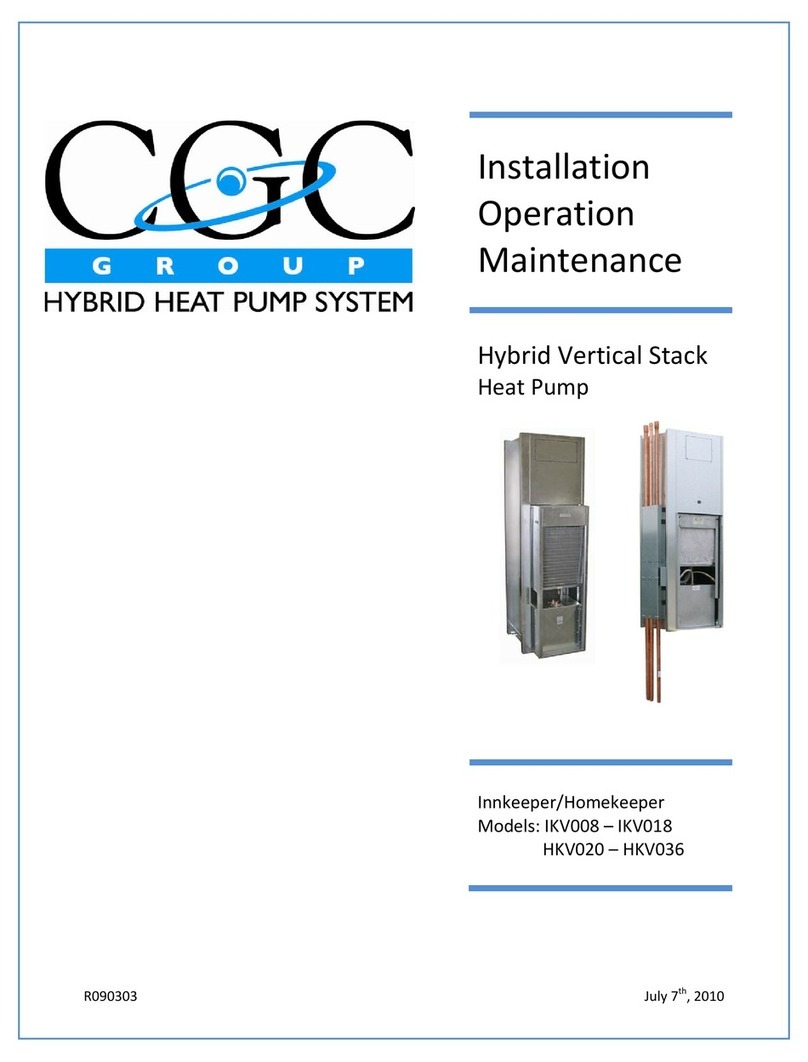
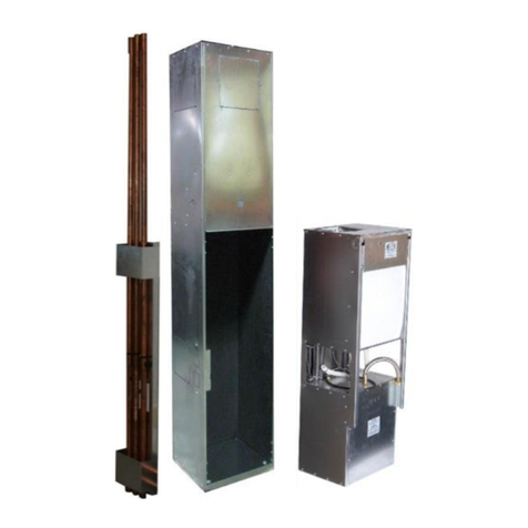
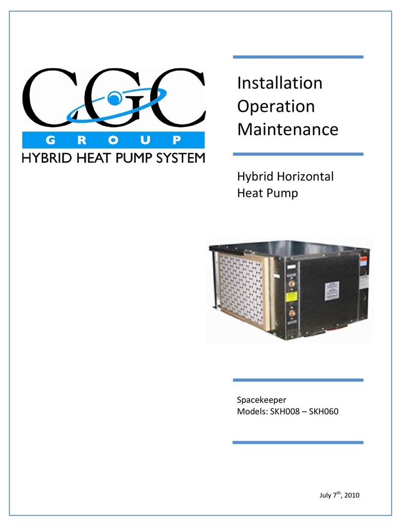
CGC SpaceKeeper SKH060 Owner's manual

R090303March4,2009
Installation
Operation
Maintenance
HybridHorizontal
HeatPump
Spacekeeper
Models:SKH008–SKH060

R090303March4,2009
TableofContents
1.INFORMATION.................................................................................................................................1
Handling/Storage..........................................................................................................................................1
Weight/Dimension/Clearances.....................................................................................................................2
2.INSTALLATION..................................................................................................................................3
GeneralInstallChecklist................................................................................................................................4
Location/Placement/Piping..........................................................................................................................5
Wiring............................................................................................................................................................6
3.OPERATION(CIRCUITPANEL)...........................................................................................................7
BoardDescription.........................................................................................................................................8
Fan.................................................................................................................................................................9
HeatOperation.............................................................................................................................................9
CoolStartUp.................................................................................................................................................9
CoolOperation............................................................................................................................................10
OperationalAlgorithm................................................................................................................................12
ThermostatConnection..............................................................................................................................12
ShutdownOutput........................................................................................................................................13
FaultAlarmOutput.....................................................................................................................................13
4.COMMISSION&STARTUP.............................................................................................................15
5.MAINTENANCE...............................................................................................................................17
SKH008‐SKH018WiringDiagram..............................................................................................................18
SKH020‐HKH060WiringDiagram..............................................................................................................19
6.APPENDIXA(DETAILS)...................................................................................................................20
SKH008‐SKH018.........................................................................................................................................21
SKH020‐HKH036........................................................................................................................................22
SKH042‐SKH060.........................................................................................................................................23

HybridHorizontalSpacekeeper–InstallationOperationMaintenanceManual
INFORMATION
R090303InstallationOperationMaintenanceManualissubjecttochangewithoutnoticePage1
Handling
Caremustbetakeninhandlingthehorizontalunitandotheraccessoriestoensurethatthis
equipmentdoesnotsustainanydamage.Itisrecommendedthatthehorizontalunitbe
transportedindividuallyonatwo–wheelcart
Theprotectiveshippingpackagingshouldbekeptonuntilreadyforinstallation.During
construction,theequipmentmustbeshelteredfromcontaminantsanddebrissuchasdrywall
dust,woodchips,orpaintthatcoulddamagethefan,orblockthecooling/heatingcoiland
diminishunitperformance.
Storage
Theunitmustatalltimesbestoredinanuprightpositionwiththecompressorsectiondown
andthefansectionorientedup.
Failuretomaintaintheunitinaverticalpositionmayresultindamagetointeriorunitpiping
andcomponentspossiblycausingpermanentunitdamage.Damageofthisnaturemayalso
resultfromdroppingtheunit.
Both,Unitshouldbestoredinacorrosivefreeenvironmentshelteredfromextreme
temperatureandhumidityconditions.Subjectingtheunittotheseconditionscouldresultin
significantlyreducedperformance,reliabilityandoperationlife.
Theunitisintendedforindooruseonly.Toprotecttheunitfromdamageduetotheelements,
andtopreventpossibleIndoorAirQuality(IAQ)contaminantsourcesfromgrowing,theunit
shouldbestoredindoors.Ifindoorstorageisnotpossible,thefollowingprovisionsforoutdoor
storagemustbemet:
1. Placetheunit(s)onadrysurfaceorriseabovethegroundtoassureadequateair
circulationbeneaththeunit.
2. Covertheunit(s)withawaterprooftarptoprotectthemfromtheelements.
3. Makeprovisionsforcontinuousventingofthecoveredunitstopreventmoisturefrom
accumulatingonunit(s)surfaces.Wetinteriorunitinsulationcanbecomeasitefor
microbialgrowthwhichhasbeendeterminedtobeacauseofodorsandserioushealth
relatedindoorairqualityproblems.
4. Storetheunitunitsintheoriginalpackaging.
5. Donotstackunits.

HybridHorizontalSpacekeeper–InstallationOperationMaintenanceManual
INFORMATION
R090303InstallationOperationMaintenanceManualissubjecttochangewithoutnoticePage2
6. Weight/Dimension/Clearance
Weight:
Model008010012015018020024030036042048060
Weight
(lb)140140140140140235235235235285285285
UnitDimension:
SEEAPPENDIXA‐Details
UnitClearance:
SEEAPPENDIXA‐Details

HybridHorizontalSpacekeeper–InstallationOperationMaintenanceManual
INSTALLATION
R090303InstallationOperationMaintenanceManualissubjecttochangewithoutnoticePage3
TheInstallationofallhorizontalProductandcomponentsandaccessoriesmustbein
accordancewithlocalcodesandallregulationsofallgoverningauthoritieshavingjurisdiction.
ThefollowinginstallationproceduresarerecommendedbytheManufacturer.Itisthe
responsibilityoftheinstallingcontractortocomplywithallapplicablecodesandregulations.
.

HybridHorizontalSpacekeeper–InstallationOperationMaintenanceManual
INSTALLATION
R090303InstallationOperationMaintenanceManualissubjecttochangewithoutnoticePage4
GENERALINSTALLATIONCHECK
Thelistbelowsummarizesthestepsrequiredtosuccessfullyinstallahorizontalunit.This
checklistshoulddefinethescopeoftheinstallationproceduresrequiredtoinstalltheunit.
1. Removepackagingandinspect
theunit.Checkforshipping
damageormaterialshortage;file
afreightclaimandnotify
appropriatesalesrepresentative,
ifdamageisfound.
2. Verifythecorrectmodel.
3. Verifythepowersupply
complieswiththenameplate
specification.
4. Connectproperlysizedand
protectedpowersupplywiring
tothedisconnect(notsupplied).
5. Installpropergroundingwiresto
anearthground.
Figure1

HybridHorizontalSpacekeeper–InstallationOperationMaintenanceManual
INSTALLATION
R090303InstallationOperationMaintenanceManualissubjecttochangewithoutnoticePage5
LOCATION
1. Determinefuturehorizontalmount
locationwithclearancesshown,in
appendixA.
2. Locatetheunitinanindoorarea.The
ambienttemperaturesurroundingthe
unitmustnotbelessthat45F(7C).Do
notlocatetheunitinareassubjectto
freezing.
PLACEMENT
1. PositiontheunitandfastentoCeiling
ensuringtheunitislevel.ExtensionRods
andRubberisolatorsaretobeused(if
supplied).
2. Provideaccessforfanandfanmotor
maintenanceandforservicingthe
compressorandcoilswithoutremoving
theunit.
3. Provideaccesstowatervalvesand
fittingsandscrewdriveraccesstotheunit
sidepanels,dischargecollarandall
electricalconnections.
PIPING
CAUTION:Pipingmustcomplywithallapplicable
codes.
1. Installshutoffvalvesateachunitto
permitunitremovalforservicing.
2. DONOTbendorkinksupplylinesor
hoses(Ifsupplied).Supplyandreturn
hosesarefittedwithswiveljointfittings
atoneendtoallowremovalforfuture
servicing.
Figure2

HybridHorizontalSpacekeeper–InstallationOperationMaintenanceManual
INSTALLATION
R090303InstallationOperationMaintenanceManualissubjecttochangewithoutnoticePage6
NOTE:Insulationofthewaterpipingloopisnotrequiredexceptwherepipingrunsthrough
unheatedareasoroutsidethebuilding.TheNormalloopoperatingtemperatureis
between85F(29C)and120F(49C).
Wiring
1. WireRoomtemperaturesensortoelectricalpanelasindicatedbythewiringdiagram.
2. Connectpower.

HybridHorizontalSpacekeeper–InstallationOperationMaintenanceManual
OPERATION
R090303InstallationOperationMaintenanceManualissubjecttochangewithoutnoticePage7
CAUTION:
Toavoidfouledmachinery,extensiveunitcleanupandvoidwarranty,donotoperateunits
withoutfiltersinplaceoruseasatemporaryheatsourceduringconstruction.
TheCGCGrouphybridheatPumpprovidesyearroundcoolingandheatingascontrolledby
yoursystemDDCcontrolpanel.
TheCGChybridheatpumpprovidescoolingwithawatercooledcompressorrefrigeration
circuitandprovidesheatingwithwarmwater.Thecompressoroperatesduringcooling
operationonlyanddoesnotoperateduringheatingoperationprovidingquieteroperating
soundlevelsandenergycostsavings.
Centralequipmentlocatedwithinthebuildingmechanicalroomisautomaticallycontrolledto
ensurethewatersuppliedtoeachheatpumpunitineachsuiteatthepropertemperature
ensuringcorrectoperation.

HybridHorizontalSpacekeeper–InstallationOperationMaintenanceManual
OPERATION
R090303InstallationOperationMaintenanceManualissubjecttochangewithoutnoticePage8
Theunitcircuitboardincorporatessixrelayoutputswiththefollowinguses:
•K1–Auxiliaryrelayforcoolingvalveonatwo‐valveunitorheatvalveonadehumidification
unit.
•K2–HeatingRelay
•K3–AlarmRelay
•K4–CompressorRelay
•K5–LowFanorFanRelayforbeltdriveunits
•K6–HighFanorCompressor#2onbeltdriveunits
EachoftheserelayshaveinparallelagreenLEDindicatorthatlightsupwhentherelayis
energized.
Theboardincorporatesdigitalinputsthatareopto‐coupledtoa24VACsource.Thesetoohave
amberLEDindicatorslocatedneartheinputlocations.Theselightupwhentheinputisclosed.
Theseinputsinclude:
•HighPressureSwitch
•LowPressureSwitch
•HeatCall(Wonthermostatterminal)
•CoolCall(Yonthermostatterminal)
•FanCall(Gonthermostatterminal)
•Auxiliary(Aonthermostatterminal)
•Compressorshutdown(24VACsignalthruO/O).
Providingacontinuous24VpotentialtoO/Owillterminateandpreventcompressor
operation.Thiscanbeusedfordutycycling,orforminimizingpowerconsumption
duringapowerfailurewhilemaintainingtheheatingfunction.
•Unitshutdown(24VACsignalthruA/O).Providingacontinuous24VACpotentialto
A/Owillterminateandpreventunitoperation.Thiscanbeusedforasimplenight
shutdown.Onbotharrangementsasinglesmall24VACcanshutdownmanyunits.¼
vaisrequiredperunit.
Finally,theboardhasfouranaloginputsprovidedviathermistors.Theseinputsareasfollows:
•Ta–DischargeAirTemperature
•Tr–RefrigerantTemperature
•Tw–Water(systemfluid)Temperature
•Co–CondensateLevel
Ta,Tr,AndTware10kOhmNTPthermistors,whileCoisa100OhmNPTthermistor.TheseInputs
donothaveLEDdisplays.

HybridHorizontalSpacekeeper–InstallationOperationMaintenanceManual
OPERATION
R090303InstallationOperationMaintenanceManualissubjecttochangewithoutnoticePage9
FAN
1. Acallon“G”forfanonthethermostatterminalstripwillcausethefantooperate
continuouslyonlowfanspeedthroughK5onmultispeedunits.
2. Acallon“W”forheatonthethermostatterminalstripwillalsocausethefanto
operateonlowspeed.After10minutesofcontinuousheatingcall,themultispeed
unitswillbeswitchedtohighspeedthroughRelayK6.
3. Acallon“Y”forcoolingonthethermostatterminalstripwillcausethefanonmulti
speedunitstoadvancetohighspeedthroughRelayK6.
4. Fanoperationwillterminatewheneverallcallsaredropped.
5. BothRelaysandtheirLED’sareenergizedonHighSpeed.
HEATOPERATION
1. Acallon“W”forheatwillturnonthefanatlowspeed.Simultaneouslyitwillenergize
theheatrelayK2anditsLED.TherelayK2willprovides24VACfusedpowerdirectlyto
theheatvalve.
COOLSTARTUP
1. Acallon“Y”forcoolinginitiatesaseriesofcheckspriortothestartupofthe
compressor.Theseare:
a. PowerONtimer–Compressoroperationisdelayedforapproximately5‐minutes
afterrestorationofpower.Thispreventsallunitscomingonlineatthesame
timethatpowerisrestored.Italsopreventscompressorjoltingwith
intermittentpower.
b. Anti‐recycletimer–Thereisa5‐minuteanti‐recycledelaytimerthatgivesthe
refrigerantcycletimeaftershutdowntoachievepressureequalizationtoallow
foranunloadedcompressorstart.
c. HighPressureSwitch–Thehighrefrigerantpressureswitchmustbeclosedprior
tostart.LED11lampwillbeON.
d. LowPressureSwitch–Thelowpressureswitchoperatesprimarilyasalossof
chargeprotector.ItmustbeclosedforcompressorstartupanditsLED12willbe
ON.Thepressureswitchhasa5minuteignoresubsequenttostart‐up.Insome

HybridHorizontalSpacekeeper–InstallationOperationMaintenanceManual
OPERATION
R090303InstallationOperationMaintenanceManualissubjecttochangewithoutnoticePage10
situations,particularlywhentheunitiscold,thepressureswitchwillopenduring
start‐up.Iftheswitchdoesnotremakewiththe5minuteignoreperiod,the
compressorwillbeimmediatelystopped.
e. AirtemperaturesensorTa–SensorTawillpreventcompressoroperationifthe
airflowingthroughtheunitisbelow60°F(15°C).
f. WatertemperaturesensorTw–SensorTwwillpreventcompressoroperationif
thesystemfluidtemperatureisabove125°F(52°C).
g. RefrigeranttemperaturesensorTr–SensorTrwillpreventcompressor
operationifthecoiltemperatureisbelow35°F(2°C).
h. AnyoftheabovefaultswillbeindicatedwiththeDiagnosticCodedescribed
underDIAGNOSTICS
COOLOPERATION
2. Monitoringoftherefrigerantcycleoperationcontinuesduringoperationofthe
compressor.Thefollowingmalfunctionswillcausecompressorshutdown:
a. Iftheheadpressureexceedsthesetpointofthehighpressureswitch,itwill
open,andthecontrolboardwillterminatethecompressoroperationwithin10
seconds.Atthistimetheflashcode6willbeinitiatedonthereddiagnosticLED
15.Compressoroperationwillberestoredinaccordancewiththe“Intelligent
reset”algorithm.
b. Ifthesuctionpressuredropsbelowthesetpointofthelowpressureswitch,the
switchwillopenandifitremainsopenbeyondthe5minuteignoreperiodafter
startup,compressoroperationwillbeterminatedwithin10seconds.
Compressoroperationwillberestoredinaccordancewiththe“Intelligentreset”
algorithm.A5flashonthereddiagnosticLED15willbeinitiatedatthistime.
c. Intelligentresetalgorithm–Ifaloworhighpressureswitchopensandremains
openformorethan10minutes,ahardlockoutwillbeinitiatedandthecooling
modewillbelockedoffuntilthecontrolsaremanuallyreset.Atthesametime
thefaultrelayK3willbesettoalarm.Ifhowever,theopenswitchcloseswithin
10minutes,arestartcycleisinitiated.Therestartcyclebeginswitha10minute
delay,afterwhichifthereisacoolcallinplaceandallotherenablersarewithin
thestartparametersthecompressorwillagainbeputintooperation.Should
eitherofthepressureswitchesopenagain,theshutdownprocedurewillcycle
again,followedbyarestart.Theintelligentresetwillallowtwoopenswitch
shutdownsandrestartsina24hourperiod,butathirdshutdownwithin24
hourswillputtherefrigerationsystemintoafullandhardlockout,requiringa

HybridHorizontalSpacekeeper–InstallationOperationMaintenanceManual
OPERATION
R090303InstallationOperationMaintenanceManualissubjecttochangewithoutnoticePage11
powerdowntoreset.Iftwoorlessswitchopenshutdownsoccurwithina24
hourperiod,theywillbeerasedfrommemoryandwillnotcontributetoafuture
hardlockout.(Ahardlockoutwillpreventcompressoroperationuntilthe
controlsarepowereddownforatleast20seconds,thegreenpowerlightgoes
out,whileasoftlockoutisacompressorshutdownthatwillberestoredoncethe
conditioncausingtheshutdownreturnstonormal.)
d. Duringcompressoroperation,refrigeranttemperature,systemfluid
temperatureanddischargeairtemperaturearecontinuouslymonitored.Ifthe
refrigeranttemperaturedropsbelow35°Fcompressoroperationwillbe
disabled.Itwillbeenabledassoonasthetemperaturerisesabove60°F.Actual
compressorrestartwillbedelayedaminimumof5minutesbytheanti‐recycle
timer.A2flashcodewillbeinitiatedwithalowrefrigeranttemperature
shutdown.
e. Ifthesystemfluidtemperaturerisesabove125°Fcompressorstartupwillbe
disabled.Itwillbeenabledassoonasthetemperaturedropsbelow120°F.Once
compressoroperationisestablished,theshutdowntemperaturewillbe
increasedto145°F.Thesystemfluidsensorismountedontheleavingfluidpipe.
Actualcompressorrestartwillbedelayedaminimumof5minutesbytheanti‐
recycletimer.A3flashcodewillbeinitiatedwithahighsystemfluid
temperatureshutdown.
f. Ifthedischargeairtemperaturedropsbelow50°Fcompressoroperationwillbe
disabled.Itwillbeenabledassoonasthetemperaturerisesabove60°F.The
dischargeairtemperaturesensorismountedonthefanscroll.Actual
compressorrestartwillbedelayedaminimumof5minutesbytheanti‐recycle
timer.A4flashcodewillbeinitiatedwithalowairtemperatureshutdown.
g. Thecondensatelevelsensorisa100ohmthermistorthatisheatedfor15
secondsevery4minutes.Itstemperatureismeasuredatthebeginningofthe
heatcycle,andagainattheendoftheheatingcycle.Ifthecondensatelevelrises
abovethesensoritwillnotwarmupduringthewarmupcycle,andthe
temperaturechangewillbeinsignificant.Itisthislackoftemperaturechange
thatthecontrollerseesasanimpendingcondensateoverflow.Whenhigh
condensatelevelisdetected,compressoroperationisimmediatelyterminated,
andatthesametimethefanisstoppedfor30seconds,andthenrestarted.At
thistimea7flashcodewillbegin.The4minutecyclewillcontinueuntilthe
coolingcallisnolongerinplace.Ifthecondensateleveldropsbelowthesensor,
compressoroperationwillbereturnedtonormal.However,ifthecondensate
levelstaysabovethesensorformorethan15minutes,thefaultalarmwillbe

HybridHorizontalSpacekeeper–InstallationOperationMaintenanceManual
OPERATION
R090303InstallationOperationMaintenanceManualissubjecttochangewithoutnoticePage12
triggered.Thisfaultsignalwillautomaticallyresetoncethecondensatelevel
goesbelowthesensor.
Note:Lastflashcodewillbemaintainedinmemoryfor1weekoruntilunitcontrolsarepowered
down.Flashcodewillcontinueunlesstheproblemhasclearedandthecompressorhasbeenput
intooperation.Ifacoolingcallisinplaceonemustremovethatcallinordertocheckthecauseof
thelastalarmshutdown.
OPERATIONALGORITHM
Thereareseveralcontrolalgorithmstopreventcyclingandproblematicoperation.Theseare:
1. Doublecall–Ifthermostatconnectionsorsetupisincorrect,resultinginasimultaneous
callforbothheatingandcooling,theunitwillnotoperate.Thisconditioncanbe
observedonthethermostatconnectionLEDs.(Note:Aheatpumpthermostatwill
presentthisscenario)
2. Reversecyclecall–Poorlylocatedautomaticchangeoverthermostats(thermostats
mountedonawalloppositeadischargegrillethatisexposedtodischargeair
temperatureswillswitchfromheattocoolcontinuously,orathermostatinadoorway
tooutside)cancausemodechangesmanytimesanhour.TheCGCcontrollerhasa10‐
minuteanti‐modechangetimerforbothheatingandcoolingmodechanges.The
controllerwillnotacceptachangeinmodefor10minutesaftertheoppositecallwas
terminated.
THERMOSTATCONNECTIONS
TheCGCcontrolboardhasbeendesignedtooperatewithmoststandard24VACthermostats.
ThesearepoweredfromtheCGCboardwith24VACandsimplyswitchpowerONtoeachofthe
Heat(W),Cool(Y),Fan(G)orAux(A).Whilemostpresentdaythermostatsoperateinthismanner
thereareothersthatmayormaynotworkproperly.Thefollowingshouldbecheckedoutfor
satisfactoryperformancepriortoinstalling:
1. HeatPumpThermostat–Someheatpumpunitsdonothaveheatrelays(thereforeare
notcompatiblewithstandardthermostats)andrequire“HeatPumpThermostats”.
Thesethermostatscallforbothheatingandcoolingononeofthesignalwires.These
thermostatsarecompletelyincompatiblewithCGC’scontroller.
2. Mercurybulbthermostat‐Thistypeisproblematicbutcanbeused.Unfortunately,the
anticipatorsareaproblem.Heatanticipatorsmustbeinserieswithahighcurrentrelay
orvalvetofunction,sodonotperformonanelectroniccircuit.Thiswillresultinlarger

HybridHorizontalSpacekeeper–InstallationOperationMaintenanceManual
OPERATION
R090303InstallationOperationMaintenanceManualissubjecttochangewithoutnoticePage13
thannormaltemperatureswings.Thecoolanticipatorifoversizedcanbleedenough
currenttoindicateacoolingcallevenafterithasbeenterminated.
3. Batterypoweredthermostats–Thesethermostatsweredevelopedasreplacementsfor
oldmercurybulbthermostatsthathad4wireconnectionswhile24Velectronic
thermostatsrequired5wires.ThesewillworkwithaCGCboard,althoughCGCdoesnot
recommendthem.Theyrequireperiodicbatteryreplacement,whichissomethingthat
shouldbeavoided.
4. Powerstealingthermostats–Thistypeiselectronicandwasalsodevelopedasa
replacementforoldmercurybulbthermostats.Thesetooareproblematicinthatthey
bleedasmallamountofcurrentdownthesignalwiresandthismaybeinterpretedasa
signalforheatorcool.
5. Triacswitchedcontrollers–Thisisacommonlyusedswitchingdeviceandallcontrollers
testedtodatehavefunctionedflawlessly.CGCrecommendsthatpriortoinstallationof
athirdpartysuppliedcontroller,itbecheckedforcompatibility.CGCcanconfirmthis.
6. Relayswitchedcontrollers–ThistypeofcontrollerworkswellwithCGCdevices.
SHUTDOWNOUTPUT
TheCGCboardhasanoptionalinputterminalstripthatallowsfortwotypesofremoteshutdown.
Thesearea)compressorshutdownandb)unitshutdown.
Theadvantageoftheseinputsisthatmanyunitscanbeconnectedinparallelandwhenpowered
byanindependent24VACsignaloneorbothoftheseactionscanbeimplemented.Commonuses
are:
a. Dutycyclingfordemandcontrol
b. Globalnightsetback
c. Heatingonlymodeduringemergencypowerperiods
TheCGCcontrollerisalsosetupsotheseshutdownfunctionscanbeinitiatedindividuallywithon
board24Vpower.Thiscapabilityallowsunitorcompressorshutdownbasedonadoorswitch,a
lightswitch,oroccupancyswitch.Aseparate24Vpowersupplyisrequirediftwoormoreunitsare
beingshutdown.
FAULTALARMOUTPUT
TheCGCboardisprovidedwithafaultalarmindicationandoutput.Thefaultalarmrelaythat
providesnormallyopenandnormallyclosedcontactsforuseintransmittingfaultconditions.
NOTE:ThefaultalarmisenergizedforNORMAL,andde‐energizedforfault.Assuchiftheunitis

HybridHorizontalSpacekeeper–InstallationOperationMaintenanceManual
OPERATION
R090303InstallationOperationMaintenanceManualissubjecttochangewithoutnoticePage14
notpowered,iftheboardfuseisblown,oriftheelectronicsaredamaged,afaultconditionwill
beindicated.
ThefaultrelayisparalleledwiththeFaultLEDwhichwillbeONwhennofaultconditionexists.
Otherfaultconditionsare:
d. Hardlockoutduetohighorlowpressureswitchbeingopenfor10minutesorlonger.
e. Hardlockoutduetothreehighorlowpressureshutdownsina24hourperiod.
f. Highlevelcondensateforinexcessof15minutes.

HybridHorizontalSpackeeper–InstallationOperationMaintenanceManual
COMMISSION&STARTUP
R090303InstallationOperationMaintenanceManualissubjecttochangewithoutnoticePage15
SystemFlushing:
Propersystemcleaningandflushingisanimportantaspectofthecommissioningandstartup
procedureforHybridUnits.Ensurethesystemhasbeenflushedproperly.Thisprevents
foulingoftheunitheatexchangers.
NOTE:Hydroniccoilsarenot100%drainable.
SystemFluid:
Ensurethatsystemwatertemperatureiswithinanacceptablerangetofacilitatestart‐up(80‐
120F)forcoolingand(100–140F)forheating
SystemWaterpH:
SystemwatershouldhaveaneutralpHbalanceofapproximately7.5,whichwillextendthelife
ofthehoses,heatexchange,andotherwatersideaccessories.
WaterFlowRate:
Openallisolationvalvestotheunit.Ensurethattheenteringandleavingfluidtemperaturesof
theHybridunitinoperationareacceptable.Typicallyan8to12degreedroporrisein
temperature,dependingonwhethertheunitisincoolingorheating.Underextreme
conditions,slightvariancesinthetemperaturemaybenoted.
FreezeProtectionfromwaterSystem:
Ensurethatfreezeprotectionisprovidedfortheoutdoorportionoftheloopwatersystem.
Inadequatefreezeprotectioncanleadtocoildamage.
NOTE:Apotentialsituationmayoccurduringconstructionwherethesystemfluidloopis
drainedafterbeingcleaned,flushedandtested.Hybridhorizontalunitwillnotcompletely
drainandmayholdfluidinthecondenserorheatingcoil.Extensivedamagemayresultto
internalcomponentsifthesystemfluidfreezesunlessadequateglycolisadded.
RemoveAirfromSystemfluidLoop:
Airinthesystemimpairsunitoperationandcancauseerosioninthesystempiping.

HybridHorizontalSpackeeper–InstallationOperationMaintenanceManual
COMMISSION&STARTUP
R090303InstallationOperationMaintenanceManualissubjecttochangewithoutnoticePage16
CleanUnitFilters:
Checktoensuretheunitfiltersareclean.Thiscontributestotheproperoperationoftheunit
byensuringadequateairflowacrossthecoil.AVacuummaybeusedtoremoveanydebrisor
dirtlodgedinorontheunits.
FanRotation:
Inspectfansectiontoensureitiscleanofanydebrisandthatthefanrotatesfreelyaswellas
belttension.
NOTE:ThisequipmentisdesignedforindoorinstallationONLY.

HybridHorizontalSpacekeeper–InstallationOperationMaintenanceManual
MAINTENANCE
R090303InstallationOperationMaintenanceManualissubjecttochangewithoutnoticePage17
WARNING:
Topreventinjuryordeathduetoelectricalshockorcontactwithmovingparts,disablethe
unitusingthedisconnectbeforeservicing.
InspectFilters:
Establisharegularmaintenanceschedule.Cleanfiltersfrequentlyandreplaceasneeded.
Toremovethefilterfromtheunitliftthefilterupandpullitoutoftheunitatthebottom.
Replacetheoldfilterbyslidingthetopedgeofanewfilterupintotherack,thenpushinginthe
bottomofthefilteruntilitdropsinplace.
CheckFanmotorsannually:
Allhybridheatpumpsarepermanentlylubricatedwhenshippedfromthefactory.Donotoil
fanmotors.Checkbelttensions,wheelspinsfreely,andnotexcessivelydirty.
VisualInspection:
Visuallyinspectunitsgivingspecialattentiontohoseassemblies.Noteanysignsof
deteriorationorcrackingandrepairleaksimmediately.
AmperageCheckoncompressorandfanmotor:
Currentdrawonthisequipmentshouldnotexceednormalfullloadorratedloadampsbymore
than10percentofthevaluesnotedontheunitnameplate.
SafetyControlReset:
Allhybridheatpumpsincludehighandlowpressurecutoutstopreventthemachinefrom
operatingatabnormalconditionsoftemperatureorwaterflow.Toresetalarmlockout,power
unitdownfor20seconds.
NOTE:Iftheunitmustberesetmorethantwice,checktheunitforadirtyfilter,abnormal
enteringwatertemperature,inadequatewaterflow(deltaTmethod)andinternal
malfunctions.Iftheunitcontinuestocutout,contactatrainedservicetechnician.

HybridHorizontalSpacekeeper–InstallationOperationMaintenanceManual
MAINTENANCE–STANDARDWIRINGDIAGRAM
R090303InstallationOperationMaintenanceManualissubjecttochangewithoutnoticePage18
This manual suits for next models
1
Table of contents
Other CGC Heat Pump manuals
Popular Heat Pump manuals by other brands

CLIVET
CLIVET WSHN-XEE2 10.2 Installation and operating manual

Zodiac
Zodiac Z200 Instructions for installation and use

Daikin
Daikin EKHBX008BA installation manual

Carrier
Carrier 42n Assembly

Trane
Trane Exergy RE 210 Installation and operation manual

Ferroli
Ferroli RVL-I PLUS Installation and maintenance manual