CGS Merlin CO2 TFT Owner's manual

Installation, Operation & Maintenance Merlin CO2 TFT
Rev 1 05-21 1
Merlin CO2 TFT
Carbon Dioxide & Temperature Monitor
CO2measured and displayed in parts per million (PPM).
Temperature can be displayed in degrees Celsius (°C) or Fahrenheit (°F).
0-10V Signal Output progress bar display.
Monitor, record and display average CO2concentration over 8 hour periods.
User friendly settings menu.
Pre-alarm and alarm relay output.
Fan controller enabled relay output.
Dual power input 110-120vac or 12-24v ac or dc.
End of Life notification for CO2 sensing element.
Automatically switch between ventilation programs when gas is used.
Boost, Mute and Wake Up feature.
Installation, Operation & Maintenance
Please read this manual carefully and retain for future use.
The Merlin CO2 TFT is designed to monitor carbon dioxide (CO2) in the air and temperature.
The monitor has a digital traffic light style display indicating the carbon dioxide levels and temperature in the area.
When CO2gas or temperature reaches alarm state –this device is able to automatically drive ventilation reducing CO2
and/or temperature.
The information contained within this manual should be referenced for typical installation and operation only.
For specific requirements that may deviate from the information in this manual –contact your supplier.

Installation, Operation & Maintenance Merlin CO2 TFT
Rev 1 05-21 2
Content
Important Warning Statements ................................................................................................ 3
Installation.................................................................................................................................. 4
Typical Location & Positioning................................................................................................................ 4
Access & Mounting ..................................................................................................................................4
Board Overview ........................................................................................................................................4
Wiring your CO2-TFT...............................................................................................................................5
Configuration Settings .............................................................................................................................6
Configuration.............................................................................................................................................6
Factory Set Condition ..............................................................................................................................7
Operation ................................................................................................................................... 8
Initial Power-Up & Indicators...................................................................................................................8
Traffic Light Indicator ...............................................................................................................................9
Alarms & Configuration............................................................................................................................9
Screen Saver Mode .................................................................................................................................9
End of Operational Life (EOL)...............................................................................................................10
General Maintenance .............................................................................................................. 10
Cleaning...................................................................................................................................................10
Auto-Calibration......................................................................................................................................10
Testing your CO2-TFT ...........................................................................................................................10
General Specification .............................................................................................................. 11

Installation, Operation & Maintenance Merlin CO2 TFT
Rev 1 05-21 3
Important Warning Statements
Please take the time to thoroughly read this user’s guide which should be retained for future reference.
The expected lifetime of the gas sensor elements is 10 years upon initial power up.
The device will display a message to indicate its end of life and should immediately be replaced.
It is recommended that this device be commissioned upon installation and serviced annually.
Do not apply lighter gas or other aerosols to the device –this will cause extreme damage.
High concentrations of alcohol found in many products may damage, deteriorate or affect the gas sensing
elements.
This device is designed to monitor carbon dioxide gas and temperature only. It is NOT designed to detect
smoke, fire or other gases and should NOT be used as such.
Never ignore your device when in alarm.
This device requires a continual supply of electrical power –it will not work without power.
This device should not be used to substitute proper installation, use and/or maintenance of fuel burning
appliances including appropriate ventilation and exhaust systems.
This device does not prevent dangerous gasses from occurring or accumulating.
Actuation of your alarm indicates the presence of dangerous levels of CO2or high temperature.
This unit may not fully safeguard individuals with specific medical conditions. If in doubt, consult a
doctor/physician.
Your product should reach you in perfect condition, if you suspect it is damaged, contact your supplier.
Manufacturer’s Warranty
Warranty coverage: The manufacturer warrants to the original consumer purchaser, that this product will be free of defects in
material and workmanship for a period of three (3) years from date of purchase.
The manufacturer’s liability hereunder is limited to replacement of the product with repaired product at the discretion of the
manufacturer. This warranty is void if the product has been damaged by accident, unreasonable use, neglect, tampering or other
causes not arising from defects in material or workmanship. This warranty extends to the original consumer purchaser of the
product only. Warranty disclaimers: Any implied warranties arising out of this sale, including but not limited to the implied
warranties of description, merchantability and intended operational purpose, are limited in duration to the above warranty period. In
no event shall the manufacturer be liable for loss of use of this product or for any indirect, special, incidental or consequential
damages, or costs, or expenses incurred by the consumer or any other user of this product, whether due to a breach of contract,
negligence, strict liability in tort or otherwise. The manufacturer shall have no liability for any personal injury, property damage or any
special, incidental, contingent or consequential damage of any kind resulting from gas leakage, fire or explosion. This warranty does
not affect your statutory rights. Warranty Performance: During the above warranty period, your product will be replaced with a
comparable product if the defective product is returned together with proof of purchase date. The replacement product will be in
warranty for the remainder of the original warranty period or for six months –whichever is the greatest.
Information on waste disposal for consumers of electrical & electronic equipment.
When this product has reached the end of its life, it must be treated as Waste Electrical & Electronics Equipment (WEEE). Any
WEEE marked products must not be mixed with general household waste, but kept separate for the treatment, recovery and
recycling of the materials used. Please contact your supplier or local authority for details of recycling schemes in your area.
Alternatively, CGS products can be securely packaged and returned clearly marked for disposal.
Installation, Operation & Maintenance Merlin CO2 TFT
Rev 1 05-21 4
Installation
Typical Location & Positioning
Consider the coverage required and function of the area. Emphasis should be placed on airflow patterns and correct
placement, not perceived detecting ranges. The target gas will only be identified when contact is made with the
sensing element itself. Your monitor should be installed in populated areas that risk high concentrations of CO2gas or
varied temperatures e.g. educational and government buildings including laboratories and commercial kitchens.
Take in to account the design of the airflow within the zone area. Avoid conditions such as; condensation; vibration;
extreme temperatures and draft zones. Avoid conditions of any other environmental factors that could potentially
impede the accuracy and operation of the detectors such as; condensation; vibration; extreme temperatures,
pressure, presence of other gases, electromagnetic interference and draft zones. Avoid positioning near draft areas
(windows and door entrances). Where possible, monitors must be fixed in such a position as to allow natural air
circulation. These recommended heights may vary based on airflow and temperature conditions in addition to the
proposed application and location.
Laboratories/educational buildings: Seated head height
Commercial kitchens: 1700mm (5.6ft) from ground level
Multiple monitors may be required to adequately protect property and/or persons!
Access & Mounting
The monitors are designed for surface mounting and must be installed by a licensed, insured contractor or competent
person. A deeper back enclosure is supplied to accommodate wiring where required.
Carefully remove the rear cover from the unit by releasing the two latching clips located at the bottom of the case. To
do this –use a small flat head screwdriver.
Using the rear cover - mark the screw holes to the wall and ensure the wall surface is flat to prevent base distortion.
There are two pre-fractured areas for cable entry provided on the inside of the rear cover, which may be cut away as
required. After executing the mounting and the connections –replace the rear cover ensuring the two clips are
latched. Make a note of the installation date on the label located on the side of the unit.
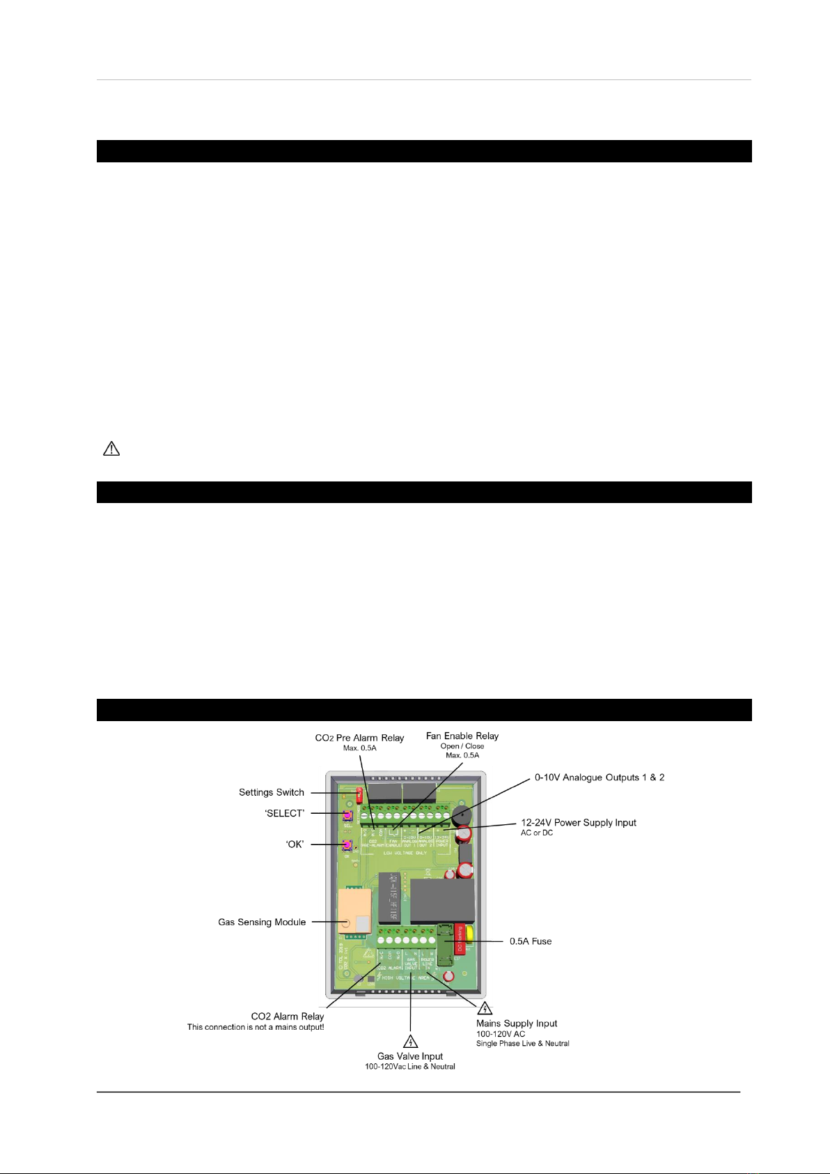
Board Overview
Installation, Operation & Maintenance Merlin CO2 TFT
Rev 1 05-21 5
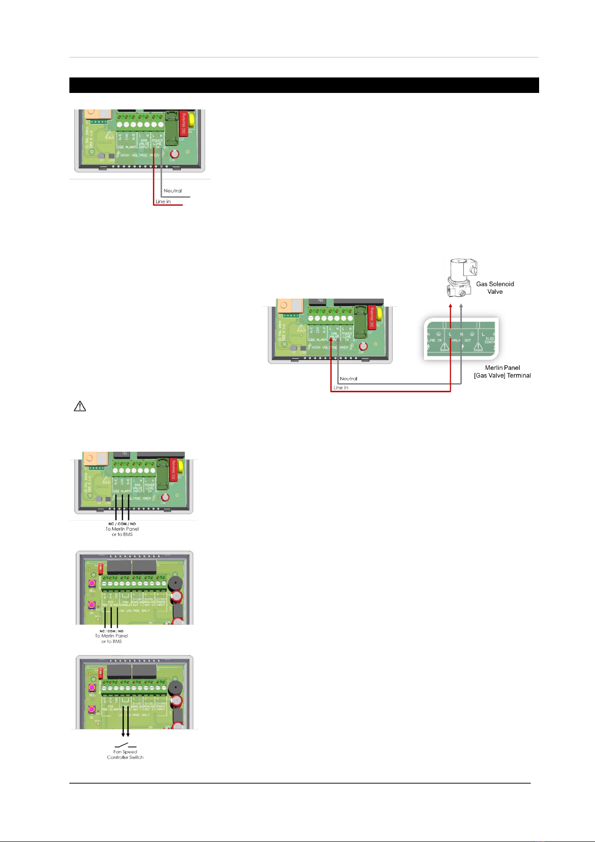
Wiring your CO2-TFT
MAINS POWER/LINE IN
(110-120vac option)
Single-phase mains power is supplied to the [POWER/LINE IN] connector.
LINE & NEUTRAL ONLY.
GAS VALVE INPUT
It is possible for your CO2 TFT to receive a signal from a gas solenoid valve via Live & Neutral terminals on our merlin
panels when wired parallel. To receive a signal you must ensure that you configure the CO2 TFT to Natural or
Mechanical ventilation mode –see settings
for ventilation types.
When gas is supplied/in use –the CO2 TFT
will receive a signal from the gas valve and
display the [GAS IN USE] message. The CO2
TFT will configure itself automatically to
operate in ‘Kitchen’ mode until the gas supply
is turned off –see ‘Settings’ for configuration.
Recommended for teaching areas with gas appliances such as laboratories and food technology rooms.
CO2 ALARM (Not a mains output)
This terminal can also connect to a building management system (BMS) or to a
Merlin panel to send an alarm signal upon alarm levels of CO2. This terminal can
also switch the Live (energise/ de-energise) a gas valve upon alarm levels of carbon
dioxide.
CO2 PRE-ALARM
This relay can send a signal to a Building Management System (BMS) or Merlin
panel when CO2 reaches pre-alarm level.
FAN ENABLE
This relay output can be connected to a fan switch which can energise fans via a
signal. This relay will switch on a fan from the current CO2 level only, by current
temperature only or by the status of both (whichever is greatest) as follows: N/C:
>600ppm / >23°C (73.4°F) N/O: <550ppm / <22°C (71.6°F)
These levels cannot be altered.
Installation, Operation & Maintenance Merlin CO2 TFT
Rev 1 05-21 6
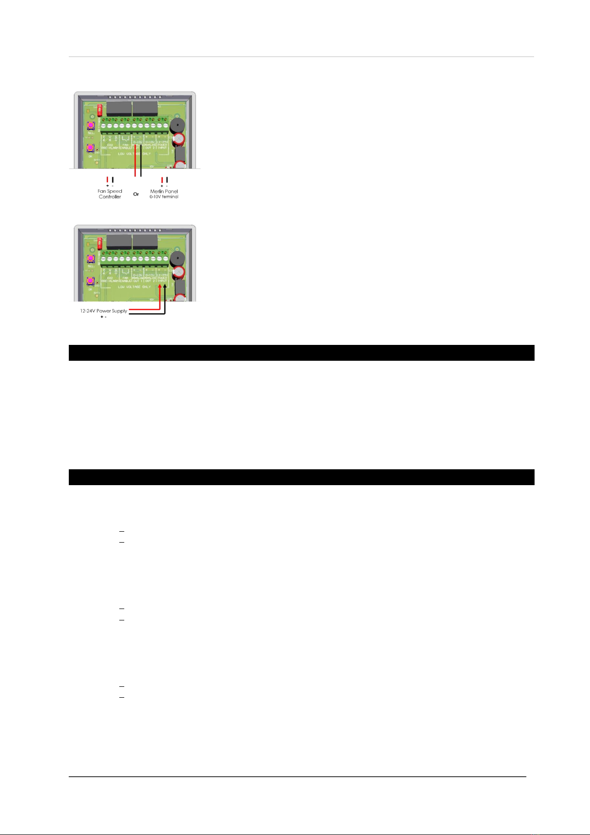
0-10V ANALOGUE OUTPUT 1 & OUTPUT 2
These connections are used to regulate external fan speed controllers (supplied
separately). Connect direct to fan speed controllers or via your Merlin panel [0-
10V] terminal if available. Minimum voltage output can be configured in settings
menu from zero to 5 volts.
0-10V output can be driven by the status of current CO2 level only, by current
temperature only or by the status of both levels (whichever is greatest).
12-24V (AC or DC) POWER
To power the CO2 TFT with 12-24v power –this should be supplied to the [12-24V
POWER INPUT] connector (+ / -).
This connection can be either AC or DC.
Configuration Settings
There is a settings switch on the CO2-TFT board. Switch it on to prompt the on-screen menu. Navigate the menu
using the buttons on the board. When changes have been made –turn the settings switch off.
[SEL.] button
Scroll through functions (highlighted red).
Change the desired setting when highlighted.
[OK] button
Highlights setting (red).
Press to save desired setting.
Configuration
NAT. - Natural Ventilation Mode (Recommended for buildings without mechanical ventilation).
Pre Alarm: >1300ppm >23 °C/ 73.4°F
Alarm: >1500ppm >25 °C/ 77.0°F
CO2 Pre-alarm relay switch: 1300ppm
CO2 Alarm relay switch: 1500ppm
0-10V Analogue Output: Linear Progression.
Min output (1-5V) from 600ppm 23 °C/ 73.4°F
Max output (10V) from 1500ppm 27 °C/ 80.6°F
Boost from: 400 - 1499ppm 0°C/32°F –26.9°C/ 80.4°F
MECH. - Mechanical Ventilation Mode (Recommended for buildings with mechanical ventilation).
Pre Alarm: >800ppm >23 °C/ 73.4°F
Alarm: >1000ppm >25 °C/ 77.0°F
CO2 Pre-alarm relay switch: 800ppm
CO2 Alarm relay switch: 1000ppm
0-10V Analogue Output: Linear Progression.
Min output (1-5V) from 600ppm 23 °C/ 73.4°F
Max output (10V) from 1000ppm 27 °C/ 80.6°F
Boost from: 400 - 999ppm 0°C/32°F –26.9°C/ 80.4°F
KITCH. –Kitchen/Gas in Use Ventilation Mode (Recommended for kitchen environments).
Pre Alarm: >1500ppm >23 °C/ 73.4°F
Alarm: >2800ppm >25 °C/ 77.0°F
CO2 Pre-alarm relay switch: 2800ppm
CO2 Alarm relay switch:4500ppm
0-10V Analogue Output: Linear Progression.
Min output (1-5V) from 600ppm 23 °C/ 73.4°F
Max output (10V) from 2800ppm 27 °C/ 80.6°F
Boost from: 400 - 2799ppm 0°C/32°F –26.9°C/ 80.4°F
Buzzer / Mute from: >2800ppm
Installation, Operation & Maintenance Merlin CO2 TFT
Rev 1 05-21 7
MIN 0-10 OUT 1
Analogue output minimum voltage.
Select: 0, 1, 2, 3, 4, 5 volt/s
MIN 0-10 OUT 2
Analogue output minimum voltage.
Select: 0, 1, 2, 3, 4, 5 volt/s
0-10V OUT 1
0-10V analogue output energised by.
Select: CO2 / TEMPERATURE / DUAL
0-10V OUT 2
0-10V analogue output energised by.
Select: CO2 / TEMPERATURE / DUAL
BUZZER
Kitchen Vent Type Mode
CO2 >2800ppm Only. Select:
ON –3 beeps every 15 seconds
10MINS –3 beeps every 10 minutes
OFF
TEMP. UNITS
Temperature measurement
Select: °C Celsius / °F Fahrenheit
BOOST (MIN.)
Analogue outputs at optimum voltage
(10V) for number of minutes. Boost can be activated only if analogue
outputs are set to either CO2 or DUAL mode only.
Select: 1, 2, 3, 4, 5, 6, 7, 8, 9, 10 minute/s
FAN ENABLE
Fan switch is energised by.
CO2 (ON >600ppm OFF <550ppm)
TEMPERATURE (ON >23°C OFF <22°C)
DUAL (Whichever is greatest)
BRIGHTNESS
Brightness of the screen display. Select:
LOW / MEDIUM / HIGH
SCREEN SAVER
ON –screen will switch off until temperature or CO2levels reach pre
alarm/ alarm status.
OFF –screen constantly on.
TEMP. ADJUSTMENT
Adjust the temperature display by up to ± 5°C or 9°F in increments of
0.1°
FACTORY RESET
Return to default condition.
YES / NO
Factory Set Condition
VENT. TYPE
KITCH.
BUZZER
ON
SCREEN SAVER
OFF
MIN 0-10 OUT 1
1
TEMP. UNITS
°C
TEMP. ADJUSTMENT
0.0°C/F
MIN 0-10 OUT 2
1
BOOST (MIN.)
1
0-10V OUT 1
TEMP
FAN ENABLE
CO2
0-10V OUT 2
CO2
BRIGHTNESS
MED
FACTORY RESET
Installation, Operation & Maintenance Merlin CO2 TFT
Rev 1 05-21 8
Operation
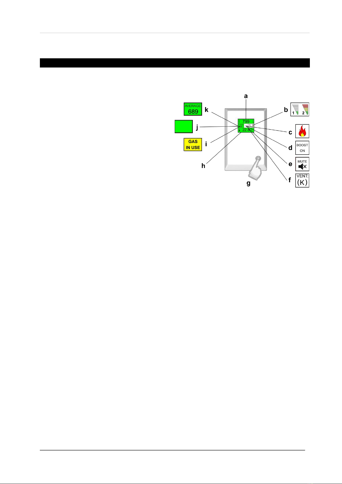
Initial Power-Up & Indicators
On connecting power, the CO2-TFT monitor enters a stabilisation phase for approximately 60 seconds –during this
period, your device not yet ready for operation.
a. CARBON DIOXIDE READING
Current CO2gas level in parts per million (ppm).
b. 0-10V ANALOGUE OUTPUT LEVEL
0-10V analogue outputs one and two.
c. FLAME ICON
Appears only when the CO2-TFT receives a signal
from a gas valve and gas supply is open/on and set
to Natural or Mechanical Ventilation Type mode.
d. BOOST ON
Message appears when BOOST is activated - press and hold the touch button (f) for three (3) seconds. The
analogue outputs will run at optimum voltage (10V) for a pre-set number of minutes. Boost can only be activated
if either analogue outputs is set to CO2 or DUAL mode only.
e. MUTE
Message appears when the touch button (f) is pressed. The audible alarm buzzer must be set to on or every 10
minutes and can only occur when gas is in use or KITCH. Ventilation mode is selected and when CO2levels rise
above 2800ppm.
f. VENTILATION MODE
Displayed under normal operation. K (Kitchen) / M (Mechanical) / N (Natural). The mode determines the
configuration and alarm levels.
g. TOUCH BUTTON
To activate Boost or Mute feature and to view the screen for 10 seconds during screen saver mode.
h. TEMPERATURE READING
i. GAS IN USE MESSAGE
Appears only when the CO2-TFT receives a signal from a gas valve and gas supply is open/on.
When the gas valve is closed, this message is not displayed.
Appears with Flame Icon.
j. BLANK –see K.
(Natural or Mechanical mode), this is left blank when the current CO2reading is below 550ppm.
In kitchen ventilation mode –this is constantly left blank.
k. AVERAGE CO2
The monitor will display the average CO2reading over periods of 8 hours and appear only when current CO2
levels reach or exceed 600ppm.
Natural or Mechanical ventilation type modes only.

Installation, Operation & Maintenance Merlin CO2 TFT
Rev 1 05-21 9
Traffic Light Indicator
Your CO2-TFT displays both current CO2and temperature levels in a traffic light style indication.
Alarms & Configuration
NAT. - Natural Ventilation Mode (N)
Green: <1300ppm <23 °C/ 73.4°F
Yellow: >1300ppm >23 °C/ 73.4°F
Red: >1500ppm >25 °C/ 77.0°F
CO2 Pre-alarm relay switch: 1300ppm
CO2 Alarm relay switch: 1500ppm
0-10V Analogue Output Progression.
Min output (1-5V) from 600ppm 23 °C/ 73.4°F
Max output (10V) from 1500ppm 27 °C/ 80.6°F
Boost from: 400 - 1499ppm 0°C/32°F –26.9°C/80.4°F
MECH. - Mechanical Ventilation Mode (M)
Green: <800ppm <23 °C/ 73.4°F
Yellow: >800ppm >23 °C/ 73.4°F
Red: >1000ppm >25 °C/ 77.0°F
CO2 Pre-alarm relay switch: 800ppm
CO2 Alarm relay switch: 1000ppm
0-10V Analogue Output Progression.
Min output (1-5V) from 600ppm 23 °C/ 73.4°F
Max output (10V) from 1000ppm 27 °C/ 80.6°F
Boost from: 400 - 999ppm 0°C/32°F –26.9°C/80.4°F
KITCH. –Kitchen/Gas in Use Ventilation Mode (K) Default
Green: <1500ppm <23 °C/ 73.4°F
Yellow: >1500ppm >23 °C/ 73.4°F
Red: >2800ppm >25 °C/ 77.0°F
CO2 Pre-alarm relay switch: 2800ppm
CO2 Alarm relay switch:4500ppm
0-10V Analogue Output Progression.
Min output (1-5V) from 600ppm 23 °C/ 73.4°F
Max output (10V) from 2800ppm 27 °C/ 80.6°F
Boost from: 400 - 2799ppm 0°C/32°F –26.9°C/80.4°F
Buzzer alarm/ Mute from: >2800ppm
The alarm thresholds and configuration will depend on which ventilation mode your CO2 TFT has been set.
There is no audio alarm for high temperatures.
Screen Saver Mode
If the screen saver mode is switched on (see settings), the CO2 TFT monitor screen will switch off when both CO2
and Temperature levels are at safe levels (green). No readings or messages will be visible during this time. The
screen will exit screen the saver mode when either the CO2or Temperature changes status (yellow or red).
To view the screen during this mode, press the touch button, the screen will be visible for 10 seconds.
SAFE
Safe CO2 levels or temperature will
be displayed GREEN.
ATTENTION!
Low CO2levels or temperature will
be displayed YELLOW.
DANGER!
High CO2levels or temperature will
be displayed RED.
Installation, Operation & Maintenance Merlin CO2 TFT
Rev 1 05-21 10
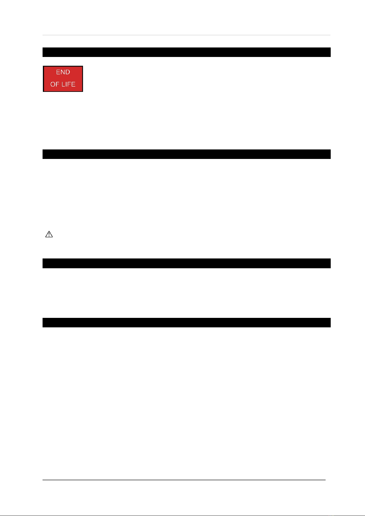
End of Operational Life (EOL)
This message indicates that the CO2 TFT monitor has reached its expected operational lifecycle.
No gas or temperature levels will be displayed. The expected lifetime is 10 years.
Contact your supplier and replace the unit immediately.
The expected lifecycle of 10 years may vary depending on environmental conditions.
General Maintenance
Cleaning
Keep your detector in good working order follow these basic principles;
Carefully remove any accumulated dust from the outer enclosure using a slightly damp cloth.
Never use detergents or solvents to clean your device –this may permenantly or temporarily damage the gas
sensing elements.
Never spray air fresheners, hair spray, paint or other aerosols near the device.
Never paint the device. Paint will seal vents and interfere with the device.
High concentrations of alcohol found in many products may damage, deteriorate or affect the gas sensing
elements –such as; wine; deodorants; stain removers; thinners etc.
Auto-Calibration
Our CO2sensors are designed to automatically recalibrate using background CO2levels ±100ppm.
For maintenance purposes, the device should be exposed to fresh air intermittently to aid with this process.
Inaccuracies that do not resolve over a 24 hour period may require temporary removal of the device, from site, for an
extended exposure to fresh air.
Testing your CO2-TFT
The aim of the test is to make sure the CO2 TFT is working at its optimum by briefly exposing a level of carbon
dioxide to send the device into an alarm state ensuring all system outputs/relays activate then it is working safely.
If the system fails to operate as intended in an alarm state, the device must not be used until a full inspection and
service has been conducted.
To do this, simply breathe near or into the device. To increase reaction time, cover the escape vents.
If in doubt, contact your supplier.
Installation, Operation & Maintenance Merlin CO2 TFT
Rev 1 05-21 11
General Specification
General
Product:
CO2 TFT
Indicators (1.8” TFT Screen)
Green (Safe), Yellow (Special State) & Red (Alarm). Detected CO2 Level. Time Weighted Average CO2
Level (TWA). Temperature. Mute. Ventilation Boost Active. End of Life.
Screen Brightness
Low –Medium –High (Plus Screen Saver)
Mounting
Wall Mounting
Electrical
Max. Power Consumption
2.16W
Power Voltage Input Range
110-120V AC 50-60Hz or
12-24V AC/ DC (Nominal 24V AC/DC Max)
Gas Valve Input
100–120vac
CO2 Pre Alarm Relay Output
Max 0.5A Signal
CO2Alarm Relay
Max 3A @ 240V
Fan Enable Relay Output
Max 0.5A Signal
Terminal Wire ratings
Copper 18AWG (0.75mm2) Min. 14 x screw terminals.
Internal Fuse
0.5A / 250V AC
Construction
Dimensions (H x W x D)
140 x 95 x 30mm / 5.51 x 3.74 x 1.18”
Unit Weight (Approx.)
0.08kg
Housing Material
Polylac - PA765
Environmental
Ingress Protection
IP40
Storage Conditions
Dry. Temp: -10 ~ 50°C / 14~ 122°F : 30 ~ 80% rh
Compliance
CE
EN 50270 / EN 61010-1
Temperature Sensor Specification
Sensor Type
Linear Active Thermistor Integrated Circuit
Measuring Range
0-95 °C / 0-203°F
Accuracy @ 25°C / 77°F
± 2°
Resolution
0.1 °C/°F
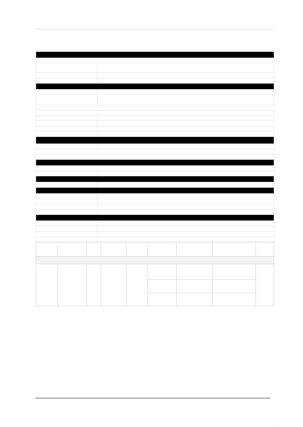
Carbon Dioxide Sensor Specification
Factory Conditions
25° ± 5°C - 77° ± 41°F (40-70% RH)
Sensor Operating Temperature
-10C° ~ 50°C (14 ~ 122°F)
Sensor Operating Humidity
Continuous 30-80% rh Non-Condensing
Sensor Operating Pressure
Normal Atmospheric Pressure ± 10%
Gas
Sensor
Indicating
Range
Steps
Accuracy
Response
(t90)
Ventilation
Alarm: 1
(Pre alarm relay)
Alarm: 2 (Latching relay)
*EOL
(Years)
NDIR. Intelligent Infrared CO2 Module. ABC Logic Auto Calibration
Carbon
Dioxide
(CO2)
400-5000ppm
1
±100ppm
<90s
Kitchen
▲2800ppm
▲4500ppm
10
Natural
▲1300ppm
▲1500ppm
Mechanical
▲800ppm
▲1000ppm
▲Rising Alarm
*EOL –Expected Operational Life

Installation, Operation & Maintenance Merlin CO2 TFT
Rev 1 05-21 12
Installation Details
Please pass this manual to the system owner / user.
Date of Installation:
Installation Location:
Organisation:
Stamp/Signature of the installer:
Every effort is made to ensure the accuracy of this document; however, CGS can assume no responsibility for any
errors or omissions in this document or their consequences. CGS would greatly appreciate being informed of any
errors or omissions that may be found in the content of this document. For information not covered in this document,
or if there is a requirement to send comments/corrections, please contact CGS using the contact details given below.
Canadian Gas Safety
Telephone: 647-577-1500
Canadian Gas Safety is the owner of this document and reserves all rights of modification without prior notice.
Table of contents
Other CGS Gas Detector manuals


Popular Gas Detector manuals by other brands


RKI Instruments
RKI Instruments 72-6ABL-C Operator's manual

Critical Environment Technologies
Critical Environment Technologies CGAS-AP installation manual

Gas Detection
Gas Detection GDA 3160 operating manual

Eastern Energy
Eastern Energy 7721 Operation manual

RKI Instruments
RKI Instruments 35-3010RK-07 manual

Honeywell
Honeywell 04230-A-1001 Technical handbook