manuals.online logo
Brands
  1. Home
  2. •
  3. Brands
  4. •
  5. Eastern Energy
  6. •
  7. Gas Detector
  8. •
  9. Eastern Energy 7721 User manual

Eastern Energy 7721 User manual

OPERATION MANUAL
WALL-MOUNT CO MONITOR
2
Model:
7722
77232
www.ete.co.th
EASTERN ENERGY CO.,LTD. (HEAD OFFICE)
40/4 Vitoondumri Rd., Banbueng, Banbueng,
Contact :
Tel: 0-3844-6117 Fax: 0-3844-6200
Email: [email protected]
Banbueng, Chonburi 20170
INTRODUCTION
Features:
Triple displays of level, temp.
and humidity (7722/77232)
s
calibration
PC connect
CO2
Stable NDIR sensor for CO detection
2
Statistics of weighted average
TWA (8 hours weighted average)
STEL(15 minutes weighted average)
Visible and audile CO warning alarm
2
Alarm output for ventilation control
ABC(Automatic Baseline Calibration)
and manual CO
2
via RS232 interface
1
Thank you for purchasing this wall mo unt
CO monitor. It could me asure the CO
2 2
level, air temp., dew point, wet bulb temp.
and humi dity (DP, WB , RH are for mo dels
7722/77232) and is an ideal instrume nt
for indoor air quality (IAQ) diagnosis.
Poor indoor air quality is considered
unhealthy because it causes tiredness,
loss of ability to concentrate, and even
illness(ex. Sick Building Syndrome ). IAQ
monitoring and survey, especially on CO
2
level and air ventilation become widely
applied in public areas such as offices,
classrooms, factories, hospitals and
hotels. It is also suggested in regulations
of industrial hygiene in some countries.
(See appendix)
With NDIR (non-dispersive infrared)
sensor used, this CO mo nitor is stable
2
in long term mo nitoring. And the built-in
alarm output is especially helpful in
ventilation control and HVAC system
performance verification.
Meter
Adaptor
Operation manual
Plain white box
This package contains:
Optional accessory:
33% calibration salt (VZ0033AZ1)
75% calibration salt (VZ0075AZ1)
RS232 cable and software
The meter is powered by an AC adaptor
(12V/1A output).
2
TWA Time weighted average(
STEL hort-term exposure limit
(15 minutes weighted
DP Dew point temp. (7722,77232)
AIR Air temp
WBT Wet bulb temp. (7722,77232)
% Unit of relative humidity
oE (C/F) Celsius/Fahrenheit
AVG/CO/
ALM/HLD
MAX/MIN Maximun/Minimum readings
8 hours)
S
average)
.
/ Vain icons in these models
%%
OO
ALM
HLD
CO2
CO2 con-
centration
in ppm
Relative
humidity in %
Air temp.
Dew point
Wet bulb
temp. in
oC or F
o
Symbols
MAX MIN AVG TWA STEL PPM
CO
MATERIAL SUPPLIED
LCD DISPLY
POWER SUPPLY
3
Enter setup mode.
Save and finish settings.
Enter CO calibration with .
2
Enter RH calibration with .
Exit setup page/mode.
Reset the meter and clear MAX/MIN.
Terminate during calibration.
Select AIR, DP, WBT temp. display.
(7722/77232 only)
Select mode or increase value in
calibration and setup.
Activate MAX, MIN, STEL,TWA
function. Select mode or decrease
value in calibration and setup.
KEYPAD
SETSET
CAL
ESC
CAL
ESC
DP/WB
M /
X
N
AVG
RESE TRESE T
DP/WB
M /
X
N
AVG
OPERATION
Plug in the adaptor and the meter turns
on automatically with a short beep. It
performs 30 sec. countdown(Fig.1) for
meter warm up, then enters normal
mode with current CO , temp.and
2
humidity(7722/77232) readings
displayed (Fig.2).
Fig. 1
Fig. 2
Model 7721/77231 Model 7722/77232
POWER ON/OFF
OO
CO2
PPM
%%
OO
CO2
PPM
or
4
%%
OO
CO2
%%
OO
CO2
Fig.3 Fig.4
TAKING MEASUREMENT
Press to switch temp. display. The
lower left LCD will cycle through air
temp., Dew point temp. (Fig.3), and wet
bulb temp.(Fig.4).
The meter starts taking measurement
after power on and updates readings
every second. In the condition of opera
-ting environment change (ex. from high
to low temp.), it takes 30 sec to respond
for CO sensor and 30 minutes for RH.
2
AIR(all models),DP,WBT(7722/77232)
DP/WB
PPM PPM
Under normal mode, press key to see
the minimum, maximum, and weighted
average readings. Press key, it
displays MIN, MAX, STEL, TWA in
sequence and returns to normal mode.
Fig.5
M /
X
N
AVG
M /
X
N
AVG
%%
OO
CO2
PPM
MAX,MIN, STEL,TWA
NOTE: Do not hold the meter close to
face in case that exhalation affects
CO levels.
2
In MIN and MAX modes, it shows the
minimum and maximum reading of
on the upper LCD. The reading of
AIR or DP or WB and humidity
on the lower LCD.
(Fig.5)
CO
2
temp.
(7722/77232) shows
In STEL and TWA modes, the upper
LCD shows the
(STEL) and 8 hours(TWA).
weighted average of
CO reading for the past 15 minutes
2
The lower
LCD shows the current AIR, DP/WB
temp. and humidity (7722/77232).
(Fig.6)
5
%%
OO
STEL
CO2
Fig.6
PPM
NOTE:
1.
If the meter is turned on for shorter
than 15 minutes, the STEL value will
be the weighted average of readings
taken since power on. Same for the
TWA value.
2.It takes at least 5 minutes to calculate
the STEL and TWA value. The LCD
shows "----" (Fig.7) during the first 5
minutes from power on.
Fig.7
The meter features visible and audible
alarm to give warnings when CO con-
2
centration exceeds the limit. Users can
set up 2 limits:
1. Upper limit: the alarm threshold
requires air conditioning
2. Lower limit: to stop the alarm.
(See page 7 P1.0 to set the alarm limits).
ALARM & OUTPUT
ALARM
%%
OO
STEL
PPM
CO2
6
LED alarm keeps blinking when beeps
are manually shut. It stops only when
readings fall below the lower limit.
ALARM OUTPUT
The meter is designed with a relay
to send output for further connection.
When CO readings go over the upper
2
limit and cause to alarm. The relay picks
up automatically and send output.
It can be connected to a ventilation
system or activator for conditioning the
air quality. The relay will drop out when
CO readings fall below the lower limit.
2
If the beeper is temporarily shut, it will
sound again when readings fall below
the lower limit and then go over the
upper limit again, or users press key
for more than 1 sec to activate it.
RESE TRESET
Alarm
Output
RS232
Adaptor
It emits beeps (Abt.80dB) with blinking
LED when CO level goes over the upper
2
limit. Beeps can be stopped by pressing
any key or automatically stop when
CO reading falls below the lower limit.
2
DP/WB
M /
X
N
AVG
Press or key to increase the value
or key to decrease. Each press tunes
100ppm and the alarm range is from
100 to 9900ppm.
7
CO2
Fig. 8
SETSET
CO2
PPM
P1.0 CO ALARM: UPPER&LOWER LIMITS
2
Fig. 9
When entering setup mode, P1.0 and
"AL" (Fig.8) are displayed on the LCD.
Press key again to enter P1.1 to set
the CO upper limit. The current setting
2
value will be blinking on the LCD(Fig.9).
CAUTION:
It’s suggested to set up the alarm
value within specification range
that accuracy is ensured. The out
of spec readings are only for
reference and not suitable to use
as alarm limits.
SETUP
SETSET
CAL
ESC
CAL
ESC
Hold key under normal mode for
more than 1 sec to enter setup mode.
To exit setup, press key in P1.0, P3.0,
or P4.0 and it returns to normal mode.
Note:
P2.0 is not applicable in these models
but for future model with CO and CO
2
measurements.
Fig. 11 Fig. 12
OO
Press key in P1.0 to access P3.0 to
set up the temperature scale(Fig.11).
Press key to enter P3.1, current
setting of °C or °F would blinking on the
lower LCD (Fig.12). Press or key to
switch °C or °F. Then press key to
save the setting or without saving
and return to P3.0.
DP/WB
SETSET
DP/WB
M /
X
N
AVG
SETSET
CAL
ESC
CAL
ESC
P3.0 TEMPERATURE SCALE
8
P4.0 ABC SELECTION
Fig. 11
ABC (Automatic Baseline Calibration)
is to implement baseline calibration to
eliminate the zero drift of the infrared
sensor. The ABC function default is on
when turning on the meter. Users can
disable it by following the procedure.
Press in P3.0 or in P1.0 to access
P4.0 to select the ABC function.(Fig.13).
Fig. 10
SETSET
CO2
PPM
SETSET CAL
ESC
CAL
ESC
When the preferred value is set, press
key to enter P1.2 (Fig. 10) to set the
lower limit. After both settings are done,
press key to save or key without
saving and return to P1.0.
DP/WB
M /
X
N
AVG
Fig.13
CO2
9
CO CALIBRATION
2
CAUTION:
1. Do not calibrate the meter in the
air with unknown CO level.
2
Otherwise, it will be taken as 400
ppm and leads to inaccurate
measurements.
2. When operating the meter in the
closed indoor areas that are not
ventilating,
be sure
to disable the ABC function to
prevent incorrect calibration.
such as hospitals or
offices with windows shut,
The meter is calibrated at standard
400ppm CO concentration in factory.
2
It’s suggested to do either ABC or
manual calibration regularly to maintain
the good accuracy.
Fig. 14 Fig. 15
CO2CO2
Press key enter P4.1 with blinking
"en" icon (Fig.14) on the lower LCD. To
disable the ABC function, press or
and "dis" blinks for choice (Fig.15).
After the preferred selection is done,
press key to save the setting or
without saving and return to P4.0.
SETSET
DP/WB
M /
X
N
AVG
SETSET CAL
ESC
CAL
ESC
Note:
When the accuracy becomes a concern
after a long time usage or other special
conditions, return to dealers for standard
calibration.
Wait about 5 minutes until the blinking
stops and the calibration is completed
automatically and return to normal
mode.
To abort the calibration, press key
for more than 1 sec.
RESE TRESET
fresh air where CO level is around 400
2
ppm.
CO2
The manual calibration is suggested to
be done in outdoor area with ventilating
Do not calibrate in the places
crowded with people or closed area with
high concentration such as
ventilating outlets or fireplaces.
Fig. 16
Place the meter in the calibration site.
Turn on the meter and hold and
keys simultaneously to enter CO
2
calibration mode (Fig.16). 400ppm and
"CAL" are blinking on the LCD while
performing calibration.
CAL
ESC
CAL
ESC
DP/WB
CO2
PPM
Manual Calibration
10
ABC (Automatic Baseline Calibration)
ABC is to calibrate the meter at the
minimum CO reading detected during
2
7 days continuous monitoring (power
on). It is supposed that the ventilating
area can have fresh air with CO level
2
around 400ppm during a period of time.
It’s not suitable to implement ABC in the
closed area with higher CO level.
2
The ABC default is on. To disable the
function, please refer to P4.0. (See p.8)
11
Plug the sensor probe into 33% salt
bottle. Hold and keys under normal
mode to enter 33% calibration (Fig.17).
" CAL" icon and calibrating value (32.7%
if at are blinking on the LCD with
current temp. at the left.
25°C)
The meter defaults to be calibrated the
humidity with 33% and 75% salt solution.
The ambient condition is recommended
to be at 25°C and stable humidity (better
to be close to the calibrating value). To
stop calibration, hold key for more
than 1 sec at any time.
(7722/77232)
RH CALIBRATION
%%
OO
Fig. 17
%%
OO
Fig. 18
After 33% calibration, plug the sensor
probe into 75% salt bottle, then press
key to enter 75% calibration (Fig.19).
CAUTION:
Do not calibrate the humidity without
the default calibration salt. Otherwise,
it will cause permanent damage.
Contact the dealers for calibration salt
or services.
M /
X
N
AVG
CAL
ESC
CAL
ESC
SETSET
RESE TRESE T
33% calibration
75% calibration
Meter is now calibrating, and will finish
in about 60 minutes when
nd humidity value stop blinking. (Fig.18)
" CAL" icon
a
12
NOTE:
Users can also calibrate either point.
To calibrate 33% only, press key to
exit when 33% calibration is completed.
To calibrate 75% only, press or
key within 5 minutes while initializing
33% calibration. And it skips 33% and
enters 75% calibration mode.
" CAL" icon and calibrating value (75.2%
if at 25°C) are blinking on the LCD with
current temp. at the left. Meter is now
calibrating. Wait about 60 minutes until
blinking stops, then calibration is
completed and it returns to normal mode.
? Error messages
E01: CO sensor damaged.
2
E02: The value is under range.
E03: The value is over range.
E04: The original data error results in
this error (RH, DP, WB)
E07: Too low voltage to measure CO2.
Check if the adaptor output is 12V.
E11: Retry humidity calibration.
E17: Retry CO calibration.
2
E31: Temperature sensor damaged.
E34: Humidity sensor damaged.
? Can’t power on
Check whether the adaptor is well
plugged.
TROUBLE SHOOTING
? Slow response
Check whether the air flow channels on
the rear were blocked.
CAL
ESC
CAL
ESC
M /
X
N
AVG
DP/WB
%%
OO
Fig.19
13
PC CONNECTION
The meter can link to PC for
data analysis
on-line
logging and via RS232
interface and software.
The protocol is as follows.
B.Format (ASCII)
Model 7721/77231
Cxxxxppm:Txxx.xC(F) LRC CRLF
Description: $CO2:Air LRC CRLF
Model 7722/77232
Cxxxxppm:Txxx.xC(F):Hxx.x%:
dxxx.xC(F):wxxx.xC(F) LRC CRLF
Description: $CO2:Air:RH:DP:WBT LRC
CRLF
A.9600 bps, 8 data bits, no parity.
SPECIFICATION
7721 7722 77231 77232
Resolution
Accuracy
Pressure
Dependence
Range
Resolution
Accuracy
Range N/A 0.0~99.9% N/A 0.0~99.9%
Resolution N/A 0.1% N/A 0.1%
±3%(10~90%) ±3%(10~90%)
±5%(others) ±5%(others)
Warm up
Operating
Storage
Power
±30ppm±5%rdg(0~5000)
Not specified for out of scale
-10.0~60.0℃ (14~140℉)
0.1℃/0.1℉
+1.6% reading per kPa deviation from
normal pressure, 100kPa
Temp.
CO2
Humidity
Range
1 ppm 1 ppm
0~2000ppm
2001~9999(out of scale)
0~5000ppm
5001~9999(out of scale)
±50ppm±5%rdg(0~2000)
Not specified for out of scale
Accuracy
30 seconds
0~50℃, 0~95%RH (avoid condensation)
±0.6℃/ ±0.9℉
-20~60℃, 0~99%RH (avoid condensation)
12V adaptor
N/A N/A
WARRANTY
The meter is warranted to be free from
defects in material and workmanship for
a period of one year from the date of
purchase. This warranty covers normal
operation and does not cover misuse,
abuse, alteration, neglect, improper
maintenance, or damage resulting from
leaking batteries. Proof of purchase is
required for warranty repairs. Warranty is
void if the meter has been opened.
RETURN AUTHORIZATION
OTHER RELATED PRODUCTS
Authorization must be obtained from the
supplier before returning items for any
reason. When requiring a RA (Return
Authorization), please include data
regarding the defective reason, the meters
are to be returned along with good packing
to prevent any damage in delivery and
insured against possible damage or loss.
Other related CO products:
2
a. Model 7752 portable Temp./CO meter,
2
general purpose.
b. Model 77532 portable Temp./CO
2
meter, high performance.
c. Model 7755 portable Temp./RH/CO
2
meter, general purpose.
d. Model 77535 portable Temp./RH/CO
2
meter, high performance.
14
CO2 LEVELS AND GUIDELINES
EPA Taiwan: 600ppm and 1000ppm
Type 1 indoor areas such as department
stores, theaters, restaurants, libraries,
the acceptable CO2 concentration of 8
hours avarge is 1000ppm.
Type 2 indoor areas with special requirements
of good air quality such as schools,
hospitals, day care centers, the
suggested CO2 level is 600ppm.
15
NIOSH recommendations
250-350ppm: normal outdoor ambient
concentrations
600ppm: minimal air quality complaints
600-1000ppm: less clearly interpreted
1000ppm: indicates inadequate ventilation;
complaints such as headaches,
fatigue and eye/throat irritation
will be more widespread. 1000ppm
should be used as an upper limit
for indoor levels.
Non-Enforced Reference levels
Regulatory exposure limit
ASHRAE Standard 62-1989: 1000ppm
CO2 concentration in occupied building should
not exceed 1000ppm.
Building bulletin 101 (BB101):
UK standards for schools say that CO2 at
1500ppm
averaged over the whole day(i.e. 9am to 3.30
pm) should not exceed 1500ppm.
OSHA: 5000ppm
Time weighted average over five 8-hour work
days should not exceed 5000ppm.
Germany, Japan, Australia, UK...: 5000ppm
8 hours weighted average in occupational
exposure limit is 5000ppm.
Appendix
Accuracy, the Zenith of
Measuring / Testing Instruments !
More products available !
Hygrometer/Psychrometer
Thermometer
Anemometer
Sound Level Meter
Air Flow meter
Infrared Thermometer
K type Thermometer
pH Meter
Conductivity Meter
T.D.S. Meter
D.O. Meter
Lux / Light Meter
Data logger
Temp./RH transmitter
Wireless Transmitter ..........
2013/08 Ver3
www.ete.co.th
EASTERN ENERGY CO.,LTD. (HEAD OFFICE)
40/4 Vitoondumri Rd., Banbueng, Banbueng,
Contact :
Tel: 0-3844-6117 Fax: 0-3844-6200
Email: [email protected]
Banbueng, Chonburi 20170

This manual suits for next models

3

Other Eastern Energy Gas Detector manuals

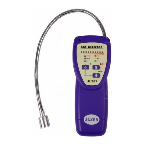
Eastern Energy JL269 LED User manual

Eastern Energy

Eastern Energy JL269 LED User manual

Eastern Energy 7201 User manual

Eastern Energy

Eastern Energy 7201 User manual

Popular Gas Detector manuals by other brands

Sensitron GAS TEST KIT instruction manual

Sensitron

Sensitron GAS TEST KIT instruction manual

Riken Keiki SD-1 operating manual

Riken Keiki

Riken Keiki SD-1 operating manual

Heath Consultants RMLD-CS HPN 105301 Operator's manual

Heath Consultants

Heath Consultants RMLD-CS HPN 105301 Operator's manual

Watts UR20S Series Technical data sheet

Watts

Watts UR20S Series Technical data sheet

Riken Keiki GD-D58-AC-GH operating manual

Riken Keiki

Riken Keiki GD-D58-AC-GH operating manual

Opera 6000 series Installation guidelines

Opera

Opera 6000 series Installation guidelines

Honeywell Rae Systems MeshGuard Deployment guide

Honeywell

Honeywell Rae Systems MeshGuard Deployment guide

Riken Keiki GP-1000 operating manual

Riken Keiki

Riken Keiki GP-1000 operating manual

iCeeO2 500P instruction manual

iCeeO2

iCeeO2 500P instruction manual

Crowcon Gas-Pro User & Operator Manual

Crowcon

Crowcon Gas-Pro User & Operator Manual

Honeywell BW Ultra user manual

Honeywell

Honeywell BW Ultra user manual

Emerson GDU-Incus Reference manual

Emerson

Emerson GDU-Incus Reference manual

IGD 2-Wire Systems Installer's guide

IGD

IGD 2-Wire Systems Installer's guide

Honeywell Searchpoint Optima Plus Safety manual

Honeywell

Honeywell Searchpoint Optima Plus Safety manual

Sona WCOB-SN-1 Installation and user guide

Sona

Sona WCOB-SN-1 Installation and user guide

Sri TCD quick start guide

Sri

Sri TCD quick start guide

Honeywell FS20X Series user manual

Honeywell

Honeywell FS20X Series user manual

Wizmart NB-983 Series user manual

Wizmart

Wizmart NB-983 Series user manual

manuals.online logo
manuals.online logoBrands
  • About & Mission
  • Contact us
  • Privacy Policy
  • Terms and Conditions

Copyright 2025 Manuals.Online. All Rights Reserved.