EDS Neptune EGLL User manual

EGLL
ADDRESSABLE GAS DETECTION
SYSTEM
ADDRESSABLE LPG GAS DETECTOR
Warranty Certificate & User Manual
www.edselectronic.com
NEPTUNE
Neptune Series
Addresable LPG Detector
Measuring Range
LPG: 0-100 %LEL

2
1
Important Information
This is the installation manual for EGLL gas detector. Please read this
instruction and all the related documents completely before installing and
operating.
Liability Limitation
To the extent allowed by the laws, EDS shall not be responsible, within the
framework of any liability whatsoever, for any loss or business loss, usage
loss, interruption of works, data loss, or any other indirect, incidental, special,
or conditional damages that arise from contract, tort, negligence, product
liability, or any other issue. Where liability related to conditional or incidental
damages is not limited or excluded within the scope of some jurisdictions, the
previous sentence may not be applicable for you. In any case, the total liability
of EDS shall not exceed the sales price of the product.
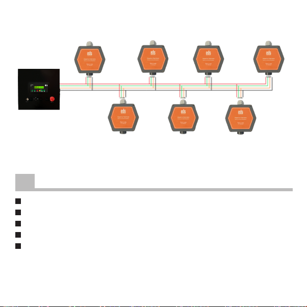
The addressable LPG gas detector has been developed to measure the
The EGLL model is designed to measure the amount of LPG gas in the
environment.
The detector measures LPG gas in the range of 0-100%LEL.
The addressable LPG gas detector is compatible with EGPL3 series panels.
DESCRIPTION

3
Gas Detector Products
Code Explanation
EGLL Addressable LPG Gas Detector, 0-100%LEL - Neptune
EGPL3 Addressable LPG Gas Control Panel - Neptune
2TECHNICAL DRAWING
100
109
140
40

4
TECHNICAL SPECIFICATIONS
3
Model EGLL
Environment Class Indoor Environment
Electrical
Communication RS485
Supply voltage range 20-28V DC
Nominal voltage 43mA
Alarm current 43mA
Sensor
Sensor Type
Catalytic
Gases Detected LPG (Butane, Propane)
Detection range 0-100 %LEL
Measurement unit %LEL
Reaction Time <10s
Warm up time 10 min
Sensor life 5 years
Measurement Accuracy %5
General
Housing Polycarbonate
Housing type Standard
Color Grey
Cabling

5
Protection class IP55
Nominal power
comsumption
<1.1W
Operating temperature
range
-30°C / +70°C
Storing temperature range -20°C / +60°C
Storage life
6 month
Dimensions (HxWxD) 109x100x41mm
Weight
121g
Mechanical resistance IEC 60335-1:2010
Production year
of manufacture. (The number on the label of the producer)
Manufacturer EDS Elektronik Destek Sanayi ve Ticaret Ltd.
Meclis Mah. Teraziler Cad. Hayran Sk. No: 4 34785
Recycling

4
This section describes the detector mounting. Please do not start the
mounting process without understanding the system, its parts and the
working principle of the system.
It is recommended to start the assembly after reading the warnings and
points to be considered.
WARNING
Anti-static measures should be taken before touching electronic materials.
Installation and maintenance must be done by authorized personnel.
Errors that may cause damage after an intervention to the device without
reading the entire user manual may exclude the device from the warranty.
Wall Mounting
First, open the detector cover.
Do the wiring of the places where 20mm cable glands will be installed.
Choose a clean and smooth wall at eye level.
vibration.
It is not recommended to be installed close to radio frequency devices.
Make sure that it is installed in a suitable area for calibration and maintenance.
For panel mounting, mount from necessary places using M4x30 mm screws
and Ø 6mm sockets.
6
MOUNTING AND CABLING

Cabling
the labels.
The terminals must be properly wired.
Cable Properties
The cable to be connected between dedector and panel should be 4x20
AWG size shielded. Maximum cable length should be 100m.
7
Figure 1: Mounting Height
For detector mounting, mount it from the necessary places using
M3x30 mm screw and Ø 6mm plastic socket.
It is recommended to mount the detector at a height of 15-25cm
(Figure 1)
Gas
Detector
15-25cm

8
3
4
1
2
2
2
2
1
11
1
4
2
3
Wall Mounting Place
Cover Screws
20M Cable Gland Connection
Sensor Place
1
2
3
Loop Connection
Addressing Button
Address LEDs
Figure 2 : Gas Detector Illustration
Figure 3 : Gas Detector Connection
Electrical Connection
Detector connections are as shown in Figure 3.
L1 L2 L3
3
4
2
12
2
1
3

Figure 3 : Gas Detector Connection
9
Figure 4 : Control Panel Detector Connections
Control Panel Detector Connections
The connection between the Detector and the Control panel is made through
loops as shown in Figure 4.
A
A
B
B
+
-
+
-

10
Power up the detector.
Make the necessary output connections.
Plug in the loop control panel.
You can see your data after automatic learning through the control panel.
In normal operation, the yellow LED lights up every 15 seconds.
FIRST OPERATION
5
6

6ADDING THE DEVICE TO THE PANEL
It is connected to its counterpart (VCC A B GND) on the panel from the
device connections.
Panel power is cut off and restarted.
To enter the automatic learning mode, the right button is pressed for 3
seconds during the initial phase.
The panel enters the auto-learning routine and registers all connected
devices with their addresses.
Discovered devices are shown on the panel display with their addresses.
The device is shown on the panel display with its address and type.
ADDRESSING
The device top cover is opened.
The detector is energized with 24V DC.
By pressing the up and down buttons, the LEDs are brought to the
position in the table below according to the desired address.
Up address is used to increase, down to decrease.
11

Note Parts marked with an x in the table indicate that it is lit.
Long press the up button again.
The lit LEDs go out and the addressing process is finished.
Between 1-12, zone 1, between 13-22, zone 2, between 23-32, the
address is used as zone 3.
12
X 11 X X X
2 X 12 X X
3 X X 13 X X X
4 X 14 X X X
5 X X 15 X X X X
6 X X 16 X
7 X X X 17 X X
8 X 18 X X
9 X X 19 X X X
10 X X 20 X X
ADD.LED5 LED5LED4 LED4LED3 LED3LED2 LED2LED1 LED1
ADD.

13
X X X
22 X X X
23 X X X X
24 X X
25 X X X
26 X X X
27 X X X X
28 X X X
29 X X X X
30 X X X X
31 X X X X X
32
ADD.LED5 LED4 LED3 LED2 LED1

14
WARNING
Make sure to make the connections properly.
Do not reverse charge and do not short circuit.
If there is a problem, turn off the power and contact the service.
TROUBLESHOOTING
7
Errors in the detector are sent to the control panel as errors.
.
If there is a communication error, the cable connections should be checked.
Breaks in the cables may cause an error.

15
Address Model Location Notes

16
RECYCLING
You could send your old devices back to our company for free recycling.
89
The above symbol indicates that this product and / or battery must not be
disposed of with household waste.
When your device has reached the end of its useful life, contact your local
authority for disposal and recycling options, take it to a collection point for the
recycling of electrical and electronic equipment or hand it over to EDS Elektronik.
Regulation on the Control of Waste Electrical and Electronic Equipment issued by
the Turkish Republic Ministry of Environment and Urbanization.
Complies with WEEE regulations.
European Union
The above symbol means that your product and / or battery must be disposed of
separately from household waste in accordance with local laws and regulations.
When this product has reached the end of its useful life, hand it in at the collection
point indicated by your local authority. The separate collection and recycling of
your product and / or battery at the time of disposal will help to conserve natural
resources and ensure that it is recycled in a manner that protects human health
and the environment

RECYCLING WARRANTY CERTIFICATE
9
The terms of the warranty is valid for products sold in Europe Union.
Failure to occur during loading, unloading and shipment after delivery of
the goods is not covered by the warranty.
Damage, malfunction and information services caused by operating
errors are not covered by the warranty.
Damage and malfunctions due to low or high voltage, faulty electrical
installation, voltage other than the voltage indicated on the product label
are not covered by the warranty.
Failures and damages resulting from natural disasters (earthquake,
The warranty is void if the document is tampered with and the original
serial number is removed.
Warranty Conditions
1. The warranty period starts from the delivery date of the product and is for
1 year.
2. The product is completely under the warranty scope of our company
including all the pieces.
3. In case of the product’s breaking down within the warranty period, so the
repair period is added to the warranty period. The maximum repair period of
the product is 20 working days.
17

This period starts from the notification date of the product’s failure to the
service station and in default of the service station, so one of those as the
product’s seller, dealer, agent, representation,importer or importer-producer.
If the product is not troubleshot with in 10 days, the importer-producer or
importer must assign another product within similar properties to the use of
the consumer till the product’s repair is completed.
4. In case of the product’s breaking down within the warranty period either
due to material and labor or mounting failures; then the repair shall be made
without requesting any charge as labor cost, shanged part fee or under any
name.
5. Despite the consumer uses the repair right;
5.1. Since the product is delivered to the consumer and provided that being
within the warranty period,
if the same failure repeats more than 2, or the different failures occur more
than 4, or the total elements of the different failures exceed 6 times with in
the specified warranty period in 1 year, as well as these failures perpetuate
not to benefit from the product,
5.2. If the maximum period required to repair is exceeded,
5.3. In the situations of the determination that the failure’s repair is
impossible with a report to be issued by the firm’s service station and in the
unavailability of the firm’s service station, respectively by one of the seller,
dealer, agent, representation, importer or importer-producer; the consumer
can request the free change of the product, refund or price discount at
defectionrate.
18

THIS CERTIFICATE HAS BEEN ISSUED UPON THE PREMISSON OF THE DIRECTORATE
GENERAL OF CONSUMER PROTECTION AND MARKET SURVEILLANCE OF THE
MINISTRY OF CUSTOMS AND TRADE WITH NUMBER 4077. 19
Producer
Stamp / Signature:
PRODUCT INFORMATION
Type of product : Addressable LPG Gas Detector
Panel :
Brand : EDS
Model : EGLL
Serial no and bandrol :
Warranty period : 1 year
Maximum repair time : 20 days
Product life time : 6 years
Delivery date and place :
Manufacturer title / Service address:
EDS Elektronik Destek San. ve Tic. Ltd. Şti.
Meclis Mah. Teraziler Cad. Hayran Sok.
No:4 34785
Sancaktepe/Istanbul/Turkey
Tel: 0216 528 45 00 Fax: 0216 314 17 80
6. The failures arising from the use of the product contrary to the particulars in
the user’s manual are outside the scope of warranty.
to the Directorate-General of Consumer Protection and Market Surveillance of
the Ministry of Customs and Trade.

EGLL-UM-2238-R1
EDS Elektronik Destek San.ve Tic. Ltd. Şti.
Meclis Mah. Teraziler Cad. Hayran sk. No:4 34785
This manual suits for next models
1
Table of contents
Other EDS Gas Detector manuals