CH Hanson NORSE 9686004 Instructions for use

650 CFM
Dust Collector
Operating Instructions & arts Manual
9643301.01 0318
Model 9686004
9686004_oipm_En011_9643301.01 03/21/18 Page 1

2
GE ING S AR ED
SAFE Y / SPECIFICA IONS
ASSEMBLY / INS ALLA ION
OPERA ION
ROUBLESHOO ING
MAIN ENANCE / REPAIR
NOR E Operating Manual & Parts List 9686004
Please read and save hese ins ruc ions. Read carefully before a emp ing o assemble, ins all,
opera e or main ain he produc described.
Pro ec yourself and o hers by observing all safe y informa ion. Failure o comply wi h ins ruc ions
could resul in personal injury and/or proper y damage! re ain ins ruc ions for fu ure reference.
Model #: ________________________
Serial #: _________________________
Purchase Da e: ___________________
9686004_oipm_En011_9643301.01 03/21/18 Page 2

GETTING STARTED
Structural Requirements
Make sure all supporting structures and load attaching devices are
strong enough to hold your intended loads. If in doubt, consult a
qualified structural engineer.
Electrical Requirements
The power supply to the Dust Collector needs to be 120 volt/ 8.0
amp, single phase, 60 Hz. The standard allowable voltage variation
is plus or minus 10%.
Tools Needed:
Standard mechanic’s hand tool set.
UN ACKING
Crates should be handled with care to avoid damage from
dropping, bumping, etc. Store and unpack crates with correct side
up. After uncrating Dust Collector, inspect carefully for any damage
that may have occurred during transit. Check for loose, missing or
damaged parts. If any damage or loss has occurred, claim must be
filed with carrier immediately. Check for completeness. Immediately
report missing parts to dealer.
Dust Collector is shipped partially assembled. End user will need to
assemble loose parts to machine.
Never use highly volatile solvents. Avoid
getting cleaning solution on paint as it
may tend to deteriorate these finishes. Use soap and water
on painted components.
Contents:
All loose parts are shipped inside the dust extractor tank. Locate
and account for the following components:
• Dust Collector Housing Assembly (1)
• Base Assembly (1)
• Filter Bag (1)
• Collector Bag (1)
• Bag Clamp (2)
• Left Support (1)
• Right Support (1)
• Support Brace (1)
• Hose (1)
• Hose Clamp (2)
• Filter Bag Hanger (1)
• Seven Piece Adapter Set (1)
• Hardware Bag (1), includes: Four M8 x 40 carriage bolts, four
M8 x 12 carriage bolts, eight M8 serrated flange hex nuts and
one 5mm hex wrench
• Operating Instructions and Parts Manual (1)
Unpack:
Open carton and carefully remove Dust Collector from packing
material. Do not discard packing materials until after machine has
been inspected for damage and completeness. Locate loose parts
and set aside.
Inspect:
• After unpacking the unit, carefully inspect for any damage that
may have occurred during transit. Check for loose, missing or
damaged parts. Shipping damage claims must be filed with the
carrier.
• All tools should be visually inspected before use, in addition to
regular periodic maintenance inspections.
• Be sure that the voltage labeled on the unit matches your
power supply.
SAFETY RULES
Do not use this dust collector in a
flammable or explosive atmosphere. Do
not use to collect aluminum or magnesium dust, nor any
other chemically reactive dusts. Consult National Fire
Protection Association (NFPA) standards before setting up a
dust collection system, especially NFPA 664.
For your own safety, read all of the
instructions and precautions before
operating tool.
PROPOSI ION 65 WARNING: Some dust created by
using power tools contain chemicals known to the state
of California to cause cancer, birth defects or other
reproductive harm.
Some examples of these chemicals are:
• Lead from lead-based paints.
• Crystalline silica from bricks and cement and other masonry
products.
• Arsenic and chromium from chemically-treated lumber.
Your risk from these exposures varies, depending on how often you
do this type of work. To reduce your exposure to these chemicals:
work in a well ventilated area and work with approved safety
equipment. Always wear OSHA/NIOSH approved, properly fitting
face mask or respirator when using such tools.
Always follow proper operating
procedures as defined in this manual even
if you are familiar with the use of this or similar tools.
Remember that being careless for even a fraction of a
second can result in severe personal in ury.
3
NOR E Operating Manual & Parts List 9686004
GE ING S AR ED SAFE Y / SPECIFICA IONS ASSEMBLY / INS ALLA ION OPERA ION ROUBLESHOO ING MAIN ENANCE / REPAIR
9686004_oipm_En011_9643301.01 03/21/18 Page 3
SAFETY RULES (CONTINUED)
Be repared for Job
• Wear proper apparel. Do not wear loose clothing, gloves,
neckties, rings, bracelets or other jewelry which may get
caught in moving parts of machine.
• Wear protective hair covering to contain long hair.
• Wear safety shoes with non-slip soles.
• Wear safety glasses complying with United States ANSI Z87.1.
Everyday glasses have only impact resistant lenses. They are
NO safety glasses.
• Wear face mask or dust mask if operation is dusty.
• Be alert and think clearly. Never operate power tools when tired,
intoxicated or when taking medications that cause drowsiness.
repare Work Area for Job
• eep work area clean. Cluttered work areas invite accidents.
• Do not use power tools in dangerous environments. Do not
use power tools in damp or wet locations. Do not expose
power tools to rain.
• Work area should be properly lighted.
• Proper electrical receptacle should be available for tool. Three-
prong plug should be plugged directly into properly grounded,
three-prong receptacle.
• Extension cords should have a grounding prong and the three
wires of the extension cord should be of the correct gauge.
• eep visitors at a safe distance from work area.
• eep children out of workplace. Make workshop childproof.
Use padlocks, master switches or remove switch keys to
prevent any unintentional use of power tools.
Tool Should Be Maintained
• Always unplug tool prior to inspection.
• Consult manual for specific maintaining and adjusting
procedures.
• eep tool lubricated and clean for safest operation.
• Remove adjusting tools. Form habit of checking to see that
adjusting tools are removed before switching machine on.
• eep all parts in working order. Check to determine that the
guard or other parts will operate properly and perform their
intended function.
• Check for damaged parts. Check for alignment of moving
parts, binding, breakage, mounting and any other condition
that may affect a tool’s operation.
• A guard or other part that is damaged should be properly
repaired or replaced. Do not perform makeshift repairs. (Use
parts list provided to order repair parts.)
Know How to Use Tool
• Use right tool for job. Do not force tool or attachment to do a
job for which it was not designed.
• Disconnect tool when changing the Filter cartridge or filter bag.
• Avoid accidental start-up. Make sure that the tool is in the OFF
position before plugging in.
• Do not force tool. It will work most efficiently at the rate for
which it was designed.
• Leave hands free to operate machine. Protect hands from
possible injury.
• Never leave tool running unattended. Turn the power off and
do not leave tool until it comes to a complete stop.
• Do not overreach. eep proper footing and balance.
• Never stand on tool. Serious injury could occur if tool is tipped
over.
• eep hands away from moving parts.
• now your tool. Learn the tool’s operation, application and
specific limitations.
The operation of any power tool can
result in foreign ob ects being thrown into
the eyes, which can result in severe eye damage. Always
wear safety glasses complying with United States ANSI
Z87.1 (shown on package) before commencing power tool
operation.
S ECIFICATIONS
Motor 3/4 HP, 3450 RPM
Voltage 120VAC
Amps 4.5
Hertz 60
Air flow rate 650 CFM
Maximum static pressure 5.8 inches H2O
Sound level 90 dBA
Hose 4˝ dia. x 78˝
Bag capacity 20 gallons
Overall size 351/4˝ x 211/4˝ x 173/8˝
Weight 55 lbs
Shipping weight 62 lbs
4
GE ING S AR ED
SAFE Y / SPECIFICA IONS
ASSEMBLY / INS ALLA ION
OPERA ION
ROUBLESHOO ING
MAIN ENANCE / REPAIR
NOR E Operating Manual & Parts List 9686004
9686004_oipm_En011_9643301.01 03/21/18 Page 4
ASSEMBLY
Refer to Figure 3.
• Attach the wheel assembly (Ref. No. 12 through 15) to base
tube (Ref. No. 10) using M6 x12 bolts, 6mm washers.
• Attach the side panels (Ref. No. 7 & 24) loosely to the base
using M8x12 bolts, 8mm washers. Do not tighten.
• Attach the housing assembly to the side panels using M5x12
bolts and nuts. Tighten all nuts.
• Insert the dust container in the bore of the top air outlet.
• Slip the filter bag (Ref. No. 1) over the container and fasten
with the retaining strap (Ref. No. 2).
• Attach the collector bag (Ref. No. 6) to the lower air outlet
using the retaining strap (Ref. No. 5).
• Attach the hose (Ref. No. 21) to the nozzle on the housing and
fasten with a hose clamp (Ref. No. 22).
• Also fasten the adapter ring to the other end of the hose using
a hose clamp.
INSTALLATION
Do not permit fingers to touch terminals
of plug when installing or removing the
plug to or from the outlet.
Do not connect to power source until unit
is completely assembled.
ower Source
• Motor is designed for operation on 120V, 60Hz.
• Normal loads will be handled safely on voltages not more than
10% above or below the specified voltage.
• Running unit on voltages not within range may cause
overheating and motor burnout.
Grounding Instructions
Refer to Figure 1
• This tool is equipped with a 3-conductor cord.
• Do not remove or alter grounding prong in any manner. In the
event of malfunction or breakdown, grounding provides path of
least resistance for electrical current to reduce risk of electrical
shock.
• Plug must be plugged into a matching outlet that is properly
installed and grounded in accordance with all local codes and
ordinances.
• The conductor with insulation having an outer surface which is
green is equipment grounding conductor. If repair or
replacement is necessary, make sure equipment grounding
conductor is not connected to line terminal.
• If power cord is worn, cut or damaged in any way, have it
replaced immediately.
Improper connection of the equipment-
grounding conductor can result in a risk
of electrical shock.
Extension Cords
• The use of any extension cord will cause some drop in the
voltage and loss of power.
• Wires of the extension cord must be sufficient in size to carry
the current and maintain adequate voltage.
• Use the table below to determine the minimum wire size
(A.W.G.) extension cord.
• Use only 3-wire extension cords having 3-prong grounding
type plugs and 3-pole receptacles which accept the tool plug.
• If extension cord is worn, cut or damaged in any way, have it
replaced immediately.
Extension Cord Length and Gauge
Length A.W.G.
Up to 25 ft. 15
NOTE: Using extension cords over 25 ft. long is not recommended.
Electrical Connections
All electrical connections must be
performed by a qualified electrician. Make
sure tool is off and disconnected from power source while
motor is mounted, connected, reconnected or anytime
wiring is inspected.
5
NOR E Operating Manual & Parts List 9686004
GE ING S AR ED SAFE Y / SPECIFICA IONS ASSEMBLY / INS ALLA ION OPERA ION ROUBLESHOO ING MAIN ENANCE / REPAIR
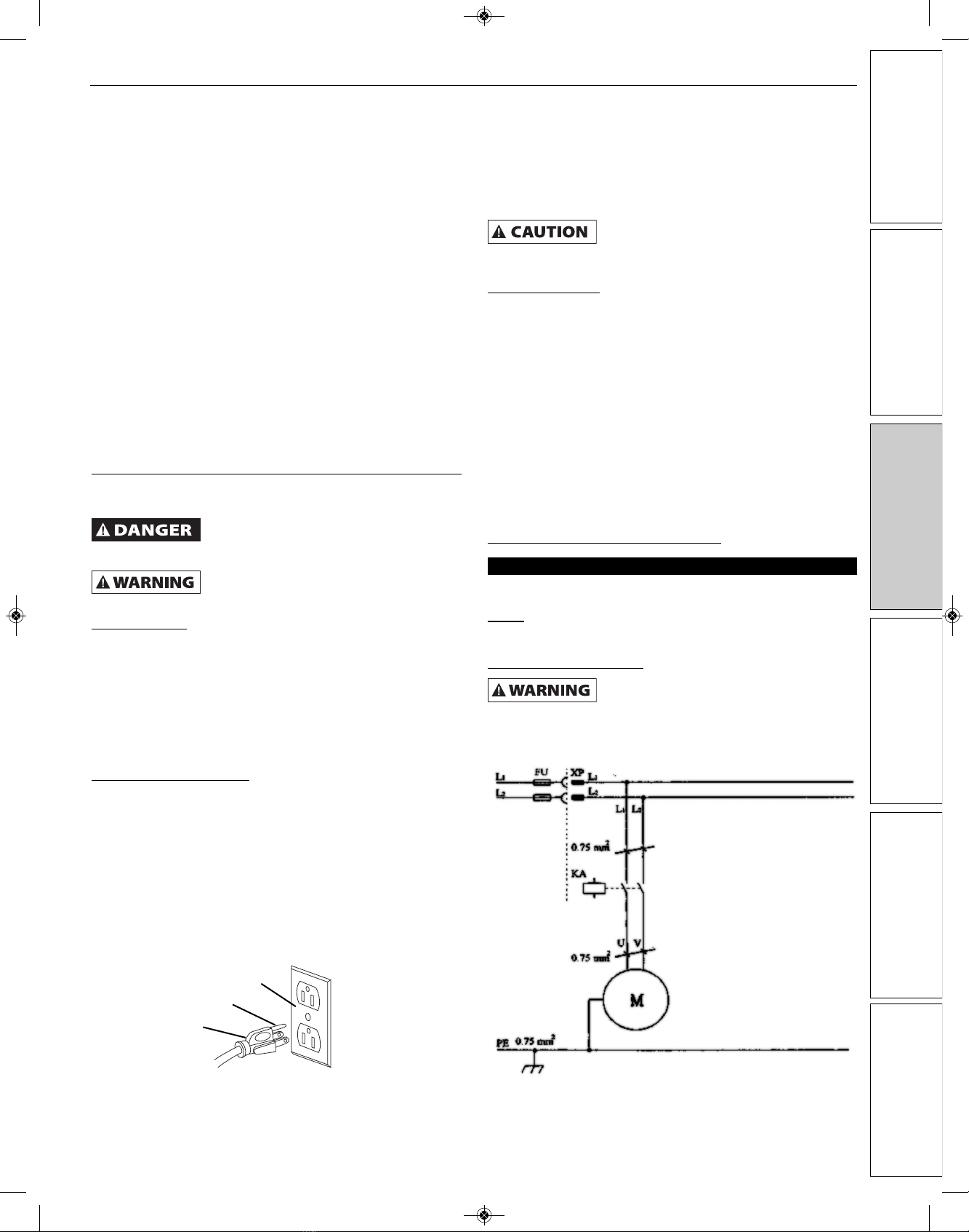
Figure 1 – roperly grounded outlet 120 Volt.
Grounding prong
3-Prong plug
Properly grounded outlet
Figure 2 - Circuit diagram.
9686004_oipm_En011_9643301.01 03/21/18 Page 5

O ERATION
Refer to Figure 3.
• Do not suck pieces of metal, large blocks of wood or pieces of
batten into the collector.
• Use only accessories designed for this Dust Collector.
• It is more efficient to use the filter cartridge than the dust bag to
collect wood chips.
1. Position dust extractor near dust producing machine on a flat
level surface.
2. Connect hose (Ref. No. 21) to dust producing machine using
hose clamp (Ref. No. 22). Use adaptors if needed.
3. Turn dust collector on before starting dust producing machine.
Emptying Collector Bag
Turn switch off and remove plug from
power source outlet before emptying
collector bag.
• The collection container should be emptied as required, but at
least after each use.
1. Empty collector bag by lifting bag clamp handle and releasing
spring connector from latch. Slide bag away from housing.
Dispose of dust properly.
2. Mount collector bag by sliding bag over opening on housing
bottom. Position the spring connector into one of the slots on
the latch and lock the clamp handle. Make sure collector bag is
secure.
MAINTENANCE
Turn switch off and remove plug from
power source outlet before maintaining
your dust extractor.
• The dust collector and filtering bag should be cleaned each
time the collection bag is changed.
• Damaged filters and bags must be replaced immediately in
order to minimize dust dispersion in the work area.
• Clean motor of dust, chips or other particles. If operation is
excessively dusty or dirty, frequent inspection of motor is
required. Vacuum any particles that may have entered the
motor.
• Replace worn, cut or damaged line cord.
• Replace worn or damaged collector hose.
• Replace worn or damaged bags.
• Frequently check that all nuts, bolts, screws, etc. have not
loosened due to vibration.
6
GE ING S AR ED
SAFE Y / SPECIFICA IONS
ASSEMBLY / INS ALLA ION
OPERA ION
ROUBLESHOO ING
MAIN ENANCE / REPAIR
NOR E Operating Manual & Parts List 9686004
9686004_oipm_En011_9643301.01 03/21/18 Page 6
7
NOR E Operating Manual & Parts List 9686004
GE ING S AR ED SAFE Y / SPECIFICA IONS ASSEMBLY / INS ALLA ION OPERA ION ROUBLESHOO ING MAIN ENANCE / REPAIR
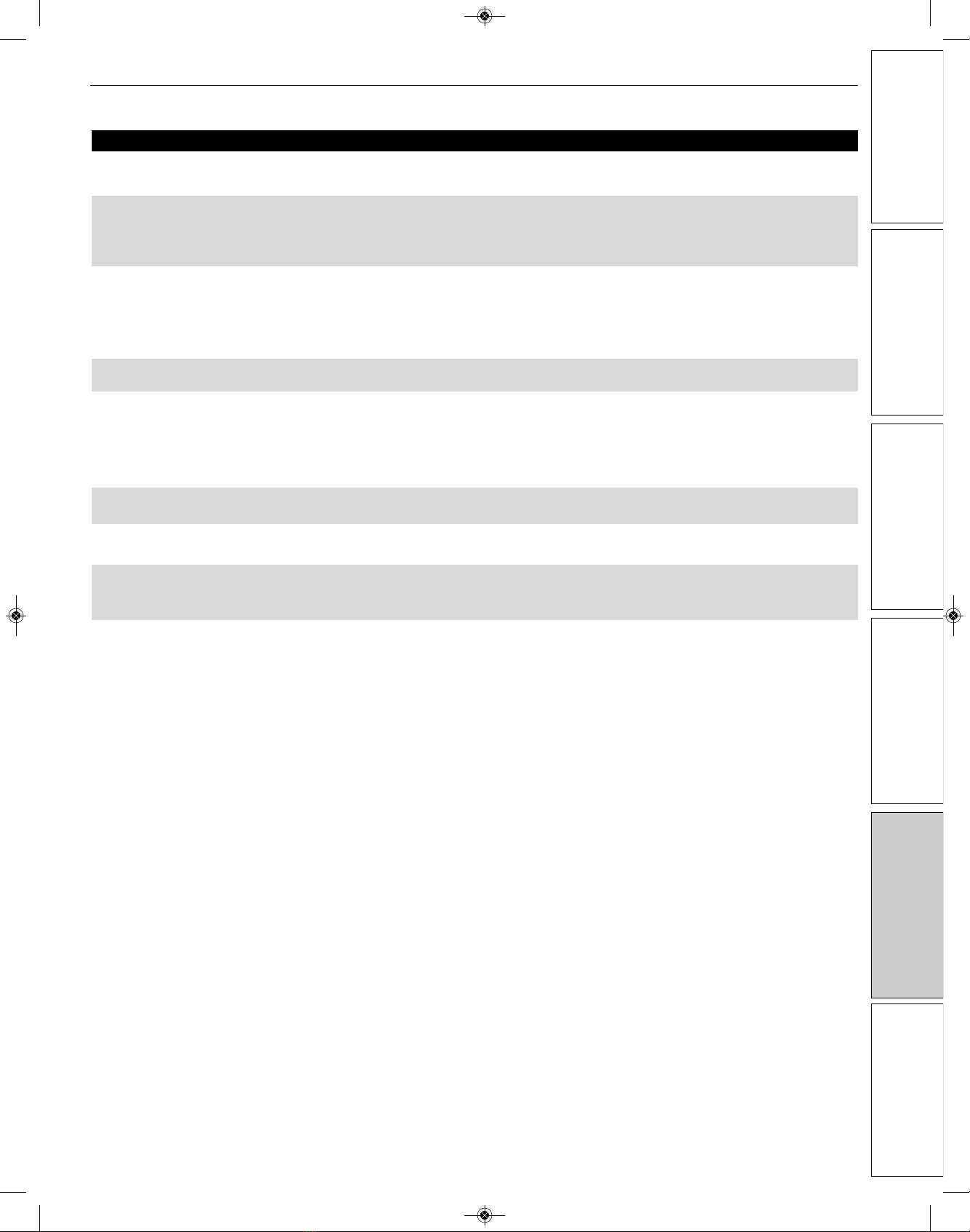
TROUBLESHOOTING GUIDE
Symptom ossible Cause(s) Corrective Action
Motor will not run
Excessive dust in air
Excessive impeller noise
Excessive motor noise
Motor fails to develop full power
or motor stalls
Motor slow to start or
fails to reach full speed
Motor overheats
Tripping circuit breaker or fuses
1. Defective plug, cord, switch or motor
2. Blown fuse or circuit breaker
1. Leaking bag or hose connection
2. Filter or collector bag leaks
1. Large debris or piece of wood in
impeller housing
2. Loose impeller
Defective motor
1. Low voltage to collector caused by
circuit overload
2. Low voltage to collector caused by
undersized extension cords
3. Low voltage from power source
1. Burned or defective motor
2. Defective motor capacitor switch
1. Motor overload
2. Improper motor cooling
1. Motor overloaded
2. Improper capacity of circuit breaker
or fuses
1. Check wiring, replace defective parts
2. Check fuse or breaker, replace
1. Check filter and collector bag connections.
Check collector hose connections
2. Dust trapped under bag clamp or collector bag
not sealed on flange
1. Do not vacuum metal materials. Turn collector
off and let debris settle in collector bag
2. Disconnect collector from power source. Re-
move lower housing (Figure 3, Ref. No. 36) and
tighten impeller
Have motor checked by qualified motor service
technician
1. Remove other electric machines or appliances
from circuit
2. Increase wire gauge size of extension cords or
shorten extension cords
3. Request voltage check from power company
1. Check motor, replace if necessary
2. Check switch, replace if necessary
1. Reduce load by slowing dust production
2. Clean sawdust from motor
1. Reduce load by slowing dust production
2. Use proper capacity circuit breaker or fuse
9686004_oipm_En011_9643301.01 03/21/18 Page 7
GE ING S AR ED
SAFE Y / SPECIFICA IONS
ASSEMBLY / INS ALLA ION
OPERA ION
ROUBLESHOO ING
MAIN ENANCE / REPAIR
NOR E Operating Manual & Parts List 9686004
8
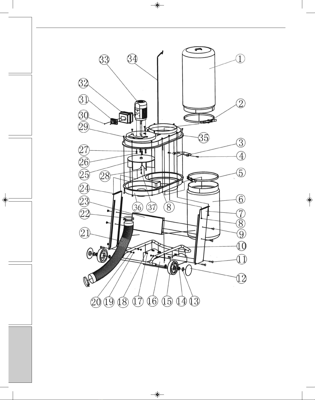
RE AIR ARTS ILLUSTRATION FOR 9686004 650 CFM DUST COLLECTOR
Figure 3 – Repair parts illustration for Dust Collector
9686004_oipm_En011_9643301.01 03/21/18 Page 8

NOR E Operating Manual & Parts List 9686004
GE ING S AR ED SAFE Y / SPECIFICA IONS ASSEMBLY / INS ALLA ION OPERA ION ROUBLESHOO ING MAIN ENANCE / REPAIR
9
RE AIR ARTS LIST FOR 9686004 650 CFM DUST COLLECTOR
1 Filter bag 9635427.00 1
2 Locking strap 9635428.00 1
3 Handgrip 9643302.01 1
4 Tapping bolt ST5.530 *
5 Locking strap 9635428.00 1
6 Collector bag 9686008.00 1
7 Left side panel 9643303.01 1
8 Nut M5 *
9 Square neck bolt M8x12 *
10 Base tube 9643304.01 1
11 Square neck bolt 40 *
12 Wheel cover 9635430.00 1
13 Circlip *
14 Washer #8 *
15 Wheel 9635430.00 1
16 Bottom plate 9643305.01 1
17 Screw M5x6 *
18 Washer #5 *
19 Nut M8 *
20 Washer #8 *
21 Hose 9635431.00 1
22 Hose clamp 9635432.00 1
23 Horizontal plate 9643306.01 1
24 Right side panel 9643307.01 1
25 Impeller 9635433.00 1
26 Hex bolt M8x12 *
27 Washer #8 *
28 Washer #6 *
29 Cup square neck bolt M5x12 *
30 Pan head tapping screw ST4.8x15 *
31 Switch 9635434.00 1
32 Switch box 9643308.01 1
33 Motor 9635435.00 1
34 Bag support 9635436.00 1
35 Upper housing 9643309.01 1
36 Lower housing 9643310.01 1
37 Screw M616 *
∆ Hose connector 9635437.00 1
∆ Connector adaptor 9635438.00 1
∆ Operating Instructions & Parts Manual 9643301.01 1
Ref.
No. Description art No. Qty.
(∆) Not shown.
(*) Standard hardware item, available locally.
(NA) Not available as replacement part.
9686004_oipm_En011_9643301.01 03/21/18 Page 9

NOTES
10
GE ING S AR ED
SAFE Y / SPECIFICA IONS
ASSEMBLY / INS ALLA ION
OPERA ION
ROUBLESHOO ING
MAIN ENANCE / REPAIR
NOR E Operating Manual & Parts List 9686004
9686004_oipm_En011_9643301.01 03/21/18 Page 10

11
NOTES
NOR E Operating Manual & Parts List 9686004
GE ING S AR ED SAFE Y / SPECIFICA IONS ASSEMBLY / INS ALLA ION OPERA ION ROUBLESHOO ING MAIN ENANCE / REPAIR
9686004_oipm_En011_9643301.01 03/21/18 Page 11
NOR E by C.H. Hanson warrants their products to be free of defects in material or workmanship. This
warranty does not cover defects due directly or indirectly to misuse, abuse, normal wear and tear, failure
to properly maintain the product, heated, ground or otherwise altered, or used for a purpose other than
that for which it was intended.
The warranty does not cover expendable and/or wear part (i.e. v-belts, screws, abrasives, jaws), damage to
tools arising from alteration, abuse or use other than their intended purpose, packing and freight. The
duration of this warranty is expressly limited to the terms noted below beginning from the date of
delivery to the original user.
The NOR E branded items carry the following warranties on parts:
All NOR E branded Tools and Accessories 1 YEAR
The obligation of NOR E by C.H. Hanson is limited solely to the repair or replacement, at our option, at its
factory or authorized repair agent of any part that should prove inoperable. Purchaser must lubricate and
maintain the product under normal operating conditions at all times. Prior to operation become familiar
with product and the included materials, i.e. warnings, cautions and manuals.
Failure to follow these instructions will void the warrant .
This warranty is the purchaser's exclusive remedy against C. H. Hanson for any inoperable parts in its
product. Under no circumstances is C. H. Hanson liable for any direct, indirect, incidental , special or
consequential damages including loss of profits in any way related to the use or inability to use our
products. This warranty gives you specific legal rights which may vary from state to state.
SERVICE & REPAIR
1. If a NOR E product requires a repair or warranty service DO NOT return the product to
the place of purchase.
2. All warranty related work must be evaluated and approved by NOR E.
3. Prior to returning any item the user must obtain factory approval and a valid RGA number.
4. For instructions and RGA number call toll free (800) 827-3398.
NORSE - a C.H. Hanson Brand
2000 N. Aurora Rd., Naperville, IL 60563 U.S.A.
or call: 1-800-827-3398
NOR E Operating Manual & Parts List 9686004
NORSE Warranty
9686004_oipm_En011_9643301.01 03/21/18 Page 12


