Chainway CW-601G User manual

1/12
OBD Telematics Dongle
CW-601GX0
User Manual

2/12
CONTENTS
1. PREVIEW.....................................................................................................................................................................3
2. DEVICE........................................................................................................................................................................3
2.1 GENERAL INTRODUCTION....................................................................................................................................................3
2.2TECHNOLOGY SPECIFICATIONS...........................................................................................................................................3
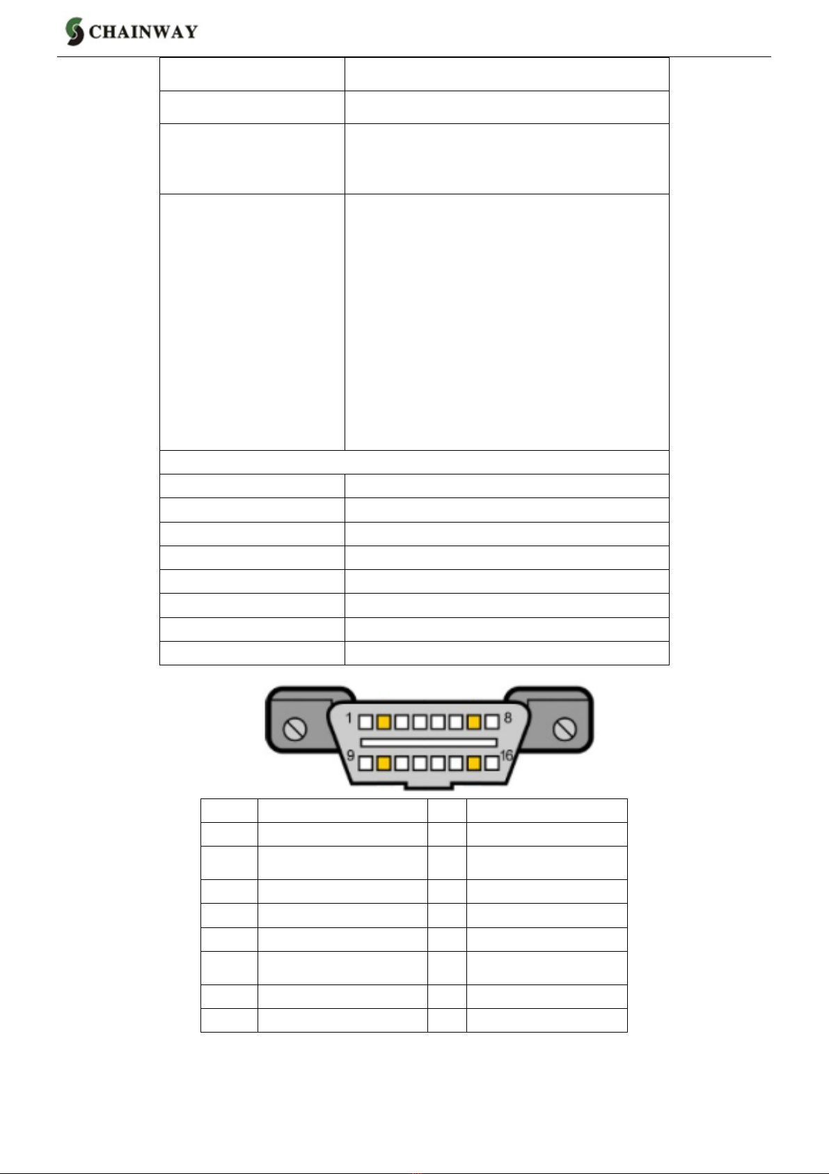
2.3 INTERFACE...........................................................................................................................................................................4
2.4 2D CODES...........................................................................................................................................................................4
2.5 INSTALLATION.......................................................................................................................................................................5
3. MAIN FUNCTIONS......................................................................................................................................................5
3.1 VEHICLE PROTECTION.........................................................................................................................................................5
3.2 VEHICLE POSITIONING.........................................................................................................................................................5
3.3 EMERGENCY RESCUE.........................................................................................................................................................6
3.4 DEVICE STATUS...................................................................................................................................................................6
3.5 MILEAGE AND FUEL CONSUMPTION COLLECTION...............................................................................................................6
3.6 DRIVING BEHAVIOR OPTIMIZING..........................................................................................................................................6
3.7 REMOTE UPDATE.................................................................................................................................................................7
3.8TROUBLE CODE DIAGNOSIS................................................................................................................................................7
4. ANDROID APP............................................................................................................................................................7
4.1INSTALLAPP.........................................................................................................................................................................7
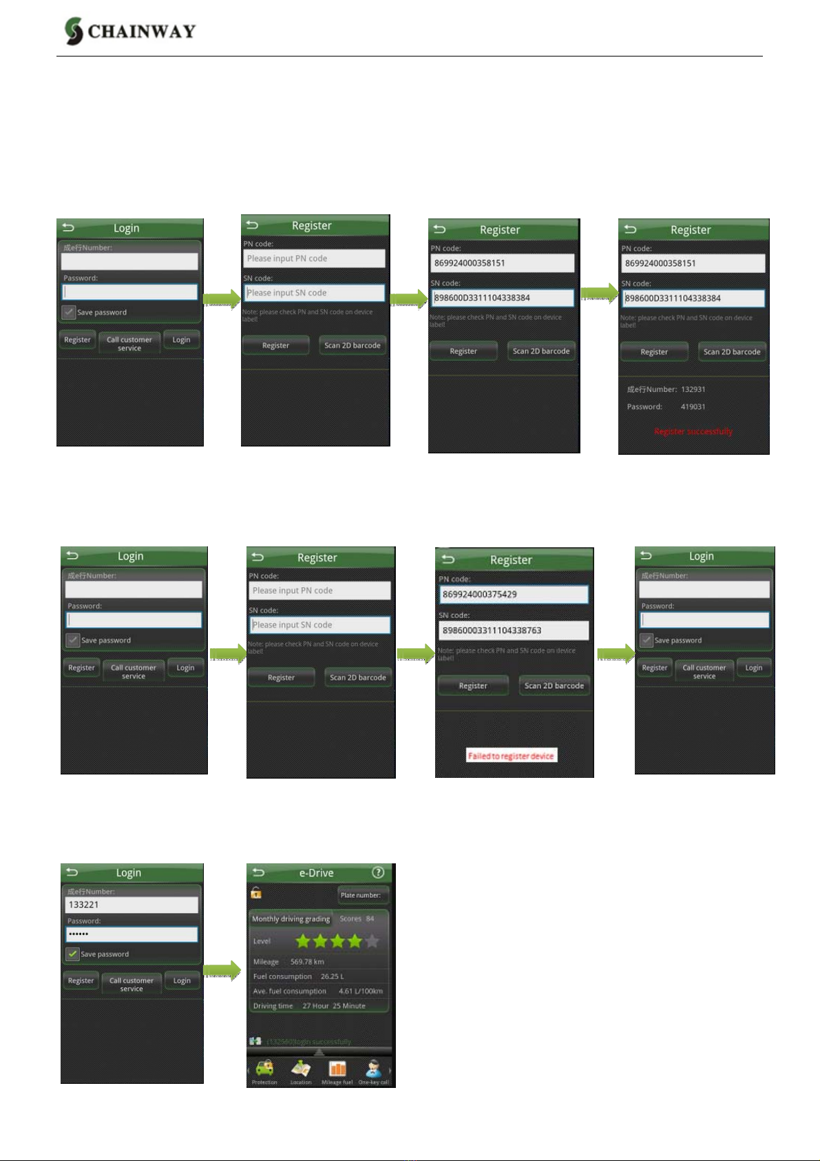
4.2 REGISTER AND LOGIN E-DRIVE NUMBER.............................................................................................................................8
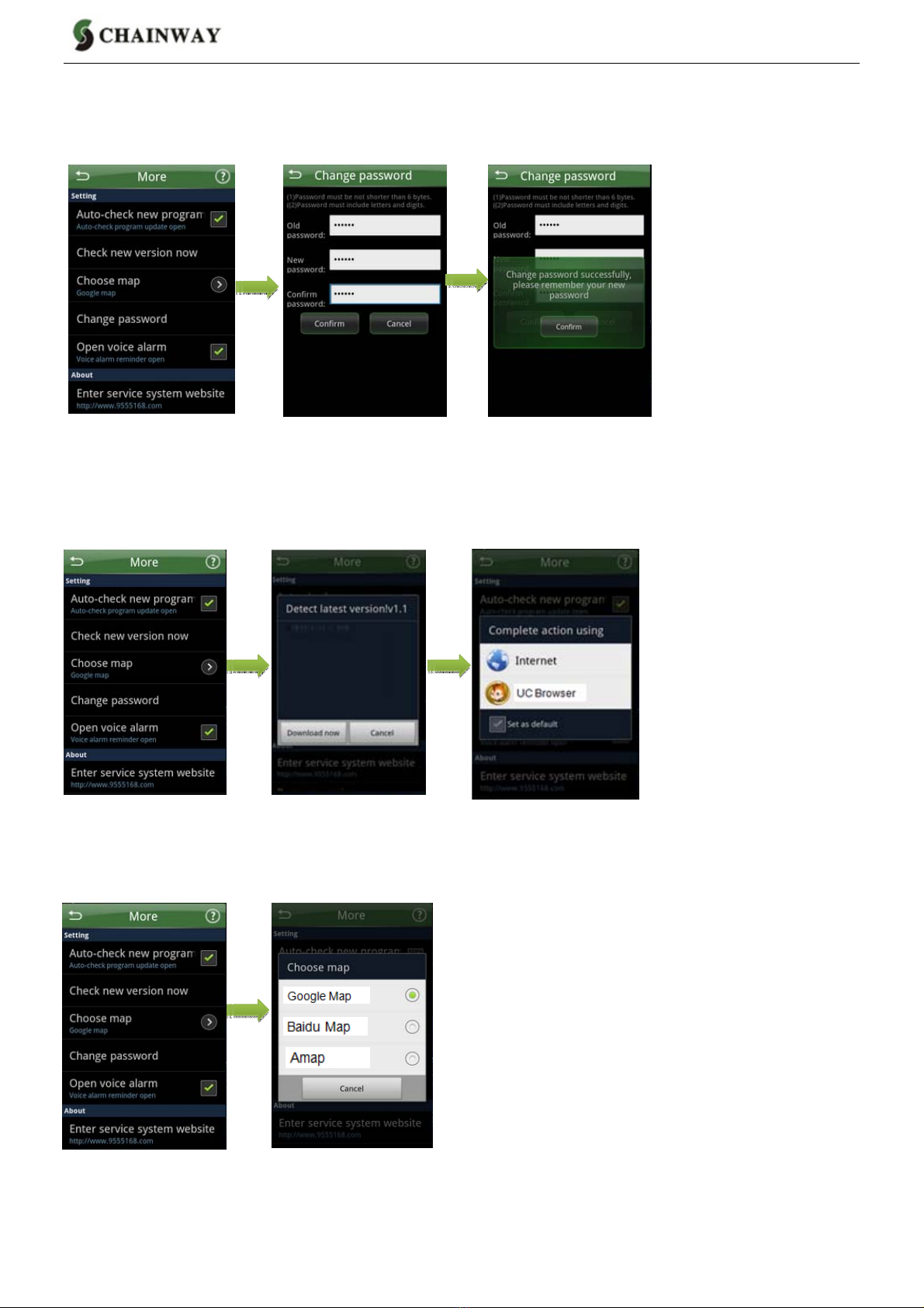
4.3 CHANGE E-DRIVE PASSWORD.............................................................................................................................................9
4.4 UPDATE PROGRAM VERSION..............................................................................................................................................9
4.5 CHOOSE MAP......................................................................................................................................................................9
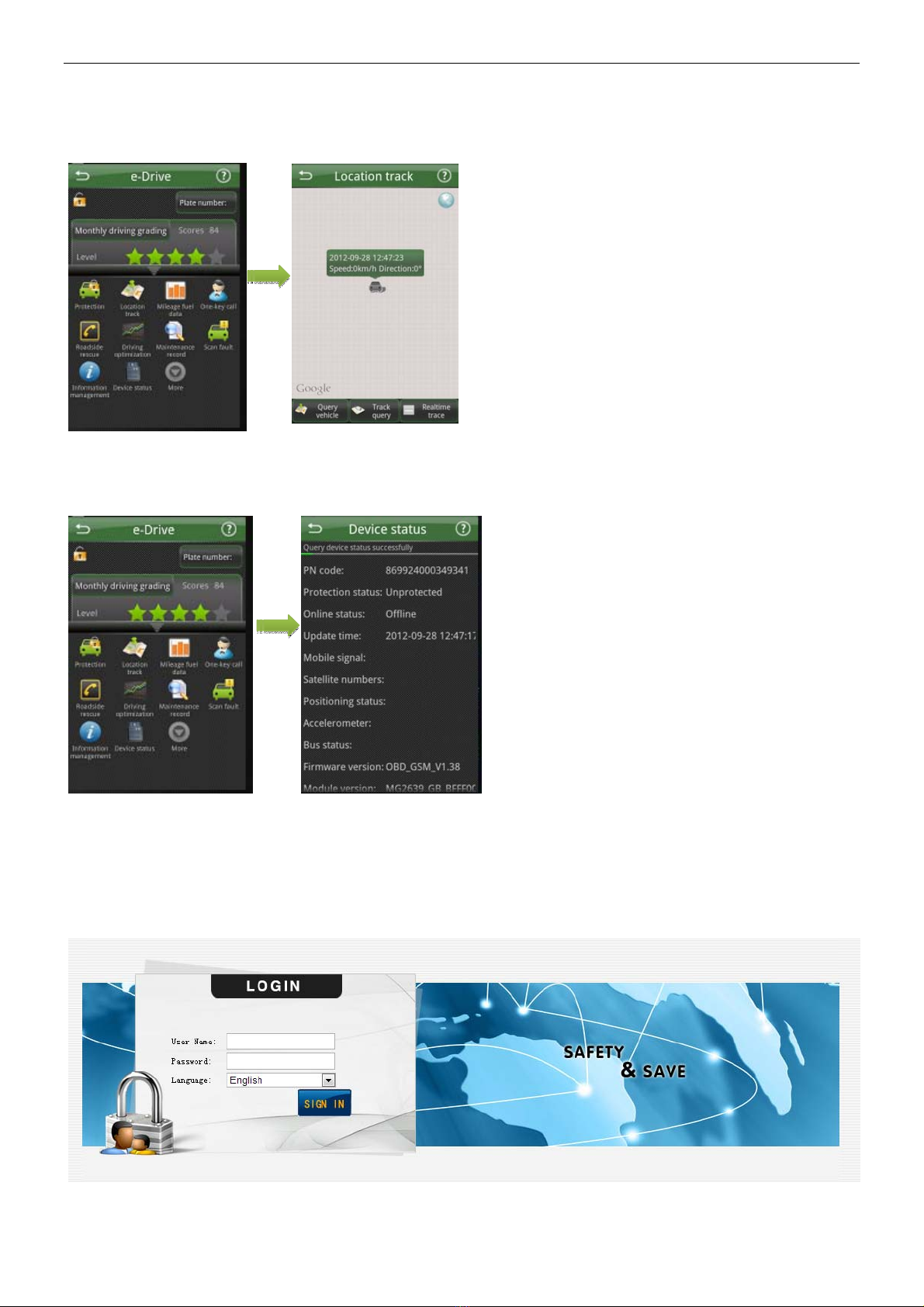
4.6 QUERY LOCATION..............................................................................................................................................................10
4.7 QUERY DEVICE STATUS.....................................................................................................................................................10
5. PLATFORM SOFTWARE.........................................................................................................................................10
5.1 LOGIN.................................................................................................................................................................................10
5.2 QUERY DAILY DRIVING DATA.............................................................................................................................................11
5.3 QUERY MONTHLY DRIVING DATA......................................................................................................................................11
5.4 QUERY YEARLY DRIVING DATA..........................................................................................................................................12
5.5 EDIT PERSONAL INFORMATION..........................................................................................................................................12
5.6 EDIT PASSWORD................................................................................................................................................................12

3/12
1. Preview
This user guide is written for end users mainly to introduce how to use our OBD telematics dongle CW-601.
2. Device
2.1 General Introduction
CW-601G is plug-and-play monitoring and diagnostic device with OBDII port and internal communication and
GPS module. It uses high performance communication module and high sensitive GPS module as well as
internal communication and GPS antennas. It supports GPRS, SMS, TCP, UDP and OTA.
It adapts advanced power management solution. It supports low power consumption and auto-sleep. It can
continue working for some time even if disconnected from automotive power.
It supports various automotive data communication protocol. It can be used for many vehicle types.
Installation is very simple and easy. User can save much time and cost compared to traditional vehicle GPS
monitoring device.
Device has been used widely for logistic, enterprise fleet, insurance, passenger transport, automotive
mortgage and rental, 4S dealers and automotive manufacturers etc.
2.2 Technology Specifications
Appearance Features
16 Pin Connector Insert in OBDII port in vehicle
Three Indicators
When device connects power at first time, three
indicators will light and blink together then turn
off. Yellow and red indicators will blink late. This
mean device has been initialized.
Yellow Indicator Quick blinking means offline, slow blinking
means online.
Red Indicator Quick blinking means no GPS signal, slow
blinking means GPS signal received.
Green Indicator Sleeping status: Indicator will blink but red and
yellow indicators will be off.
Working mode: Indicator will be off.
USB Port Locally update firmware and debug program
GPS Antenna Internal
Communication Antenna Internal
Technology Parameters
CPU NXP ARM7

4/12
GPS Module U-Blox
Communication Module GSM850/900/1800/1900MHz
3D Accelerometer Range:±2g/±4g/±8g
Dynamic, Optional
Output data rate(ODR): 1.56-800Hz
Protocol
ISO 15765-4 (CAN)
ISO 14230-4 (Keyword Protocol 2000)
ISO 9141-2 (Asian, European, Chrysler
vehicles)
SAE J1850 VPW (GM vehicles)
SAE J1850 PWM (Ford vehicles)
ISO 15765
ISO 11898 (raw CAN)
SAE J1939 protocol
General Statement
Material ABS
Size 62*48*20mm
Weight 70g
Battery 50mAh li-polymer
Battery DC 9 - 32V
Current 70mA (Working), 20mA(Sleeping)
Working Temperature -30℃-75℃
Working Humidity 95%(Non-condensed)
2.3 Interface
PIN Function PIN Function
1 NC 9 NC
2 SAEJ1850 bus + 10 SAEJ1850 BUS-
3 NC 11 NC
4 Vehicle body GND 12 NC
5 Signal GND 13 NC
6 CANBUS HIGH 14 CANBUS LOW
7 K line 15 L or K2 line
8 NC 16 Power +
2.4 2D Codes
There is 2D code on device. It is used to indicate device. The codes include PN and SN:
-50

5/12
PN:Product number, 15 digits, the only identification for device
SN:Serial number, 20 digits, also the only one
2.5 Installation
It is very easy to install device. User only need insert device in OBDII port in vehicle. Different vehicle maybe
have different OBDII position. User can query device status after finishing installation.
3. Main Functions
3.1 Vehicle Protection
Vibration alarm: set protection status on smart phone APP. If device has inspected that vehicle is vibrating
under sleeping status, device will wake up automatically and send alarm after being online.
Starting alarm: set protection status on smart phone APP. If device has inspected that engine is turned on
under sleeping status, device will wake up automatically and send alarm after being online. Special situation:
there will be illegally starting alarm if engine is turned on before the first-time online that device goes online
before installation or wakes up regularly.
Special situation: device will issue illegal starting alarm if the vehicle is ignited before online at first time or
timing wake-up. This is starting alarm under special situation. APP will tell there is illegal starting alarm.
Moving alarm: set protection status on smart phone APP. If device has inspected vehicle is moving under
sleeping status, device will wake up automatically and send alarm after being online.
Power disconnection alarm: device will send power disconnection alarm message to the server. The alarm
message will be shown on platform software.
3.2 Vehicle Positioning
When speed is more than 8km/h and turn is more than 50°, device will send position information including
positioning time, GPS speed, meter speed, direction, altitude, position and ignition status information in order
to improve driving trace accuracy.
When there is harsh acceleration, harsh deceleration, harsh turn, protection alarm and emergency alarm,
device will send position information including positioning time, GPS speed, meter speed, direction and altitude
etc.
Users can query driving trace on platform or smart phone APP calculated according to the above position

6/12
information.
3.3 Emergency Rescue
Rollover alarm: if vehicle rolls over during driving (three-axis acceleration sensor detects that rollover degree is
more than 60°), device will send alarm and make emergency rescue call.
Impact alarm: if vehicle impacts during driving (three-axis acceleration sensor detects that acceleration is more
than 19.6 m/s²), device will send alarm and make emergency rescue call.
Smart phone APP dose not distinguish rollover alarm and impact alarm, both are considered as emergency
alarm.
If there is impact or rollover during sleeping, device will wake up and send alarm after being online. If there is
impact or rollover during working, device will send alarm immediately.
3.4 Device Status
Device indicators status: when device gets power at first time, three indicators will blink at same time and then
turn off. The yellow and red indicators will blink after that, which means initialization has been finished. The
yellow is online indicator, quick blinking means offline, slow blinking means online. The red is positioning
indicator, quick blinking means not fixed position, and slow blinking means fixed position.
Device status query: when device is online, user can query status by smart phone APP, can obtain detailed
working status and know current working status.
Uploading contents: device ID, protection status, online status, status update time, communication signal
strength, satellites positioning status, accelerator sensor status, bus connection status, device firmware
version, module version and runtime etc.
Device sleeping: if device starts at first time, device will keep online until device sleep after fixing position. If
device does not fix position in 25 minutes, it will sleep soon. If device has already fixed position, it will sleep in 2
minutes. Device will wake up 1 time every 1 hour during sleeping, and then sleep again after 200 seconds.
3.5 Mileage and Fuel Consumption Collection
Mileage collection: device can collect GPS speed and meter speed to calculate interval mileage and send to
platform. Platform works out total mileage according to interval mileages.
Fuel consumption collecting: device can connect BUS to collect interval fuel consumption data and send to
platform. Platform works out total fuel consumption according to interval fuel consumption data, and make
various fuel consumption diagrams.
3.6 Driving Behavior Optimizing
Device can collect harsh acceleration, harsh deceleration, high engine revolution times, mismatch between

7/12
speed and revolution, over speed times and idle times etc and send to platform for calculation and statistics.
Smart phone APP grades driving behavior according to platform data.
Over speed: if driving speed is over than preset speed and last preset time, it will be considered as over speed.
Harsh acceleration: when acceleration in 2 seconds is more than preset acceleration, it will be considered as
harsh acceleration.
Harsh deceleration: if deceleration in 2 seconds is more than preset deceleration, it will be considered as
harsh deceleration.
Harsh turn: if turn in 5 seconds is more than 50° and driving speed is more than 3.5 km/h, it will be considered
as harsh turn.
High revolution: if revolution is more than preset revolution, it will be considered as high revolution.
Speed not matches revolution: device obtains vehicle speed and engine revolution, and then check whether
the matching relation between the revolution and the speed has obeyed the preset matching relations.
Idle times: if vehicle keeps static status or speed is always less than preset value, it will be considered as idle
status. The idle times will add one more every 10 minutes if vehicle is in idle status. Idle times are judged by
ignition and speed.
3.7 Remote Update
Device supports automatically update and manual update.
Automatically update: platform configure update files. Platform sends synchronization parameters when device
is online. If it is different version, device will start to update automatically.
Manual update: platform sends update command when device is online. If it is different version, device will
start to update. Device will restart and run new program after finishing update.
Device can keep waking up during update until finishing update.
3.8 Trouble Code Diagnosis
Device supports various protocols. It can read vehicle fault information and send to server. User can check
detailed fault information on smart phone APP.
4. Android APP
4.1Install APP
Please contact your local service provider to get Android APPAPK and install in your smart phone.

8/12
4.2 Register and login e-Drive number
4.2.1 Register
Register successfully
Login e-Drive APP -> Register -> Scan 2D code (on device) -> Register e-Drive number -> Register
successfully
Failed to login
Login e-Drive APP -> Register -> Scan 2D code(on device) -> Register e-Drive number -> Failed to register ->
Call customer service
4.2 .2 Login
Input e-Drive number and password -> Login -> Enter homepage

9/12
4.3 Change e-Drive Password
Main menu -> More -> Set -> Change password -> Input new password -> Ensure
4.4 Update Program Version
Check new version soon
Main menu -> More -> Check new version -> Download soon -> Choose download method -> Install
4.5 Choose Map
Main menu -> Choose map -> Choose

10/12
4.6 Query Location
Main menu -> Location trace -> Query location
4.7 Query Device Status
Main menu -> Device status
5. Platform Software
5.1 Login
Login address is based on server, please input correct address. Login page is as below:

11/12
After login successfully and enter software, the home page is as below:
5.2 Query Daily Driving Data
Main menu -> Driving data -> Daily driving data
5.3 Query Monthly Driving Data
Main menu -> Driving data -> Monthly driving data

12/12
5.4 Query Yearly Driving Data
Main menu -> Driving data -> Yearly driving data
5.5 Edit Personal Information
Main menu -> User info
5.6 Edit Password
Main menu -> Password reset

This device complies with part 15 of the FCC rules. Operation is subject to
the following two conditions: (1) this device may not cause harmful
interference, and (2) this device must accept any interference received,
including interference that may cause undesired operation.
Changes or modifications not expressly approved by the party responsible
for compliance could void the user’s authority to operate the equipment.
Note: This equipment has been tested and found to comply with the limits
for a Class B digital device, pursuant to part 15 of the FCC Rules. These limits
are designed to provide reasonable protection against harmful interference
in a residential installation. This equipment generates, uses and can radiate
radio frequency energy and, if not installed and used in accordance with the
instructions, may cause harmful interference to radio communications.
However, there is no guarantee that interference will not occur in a particular
installation. If this equipment does cause harmful interference to radio or
television reception, which can be determined by turning the equipment off

and on, the user is encouraged to try to correct the interference by one or
more of the following measures:
—Reorient or relocate the receiving antenna.
—Increase the separation between the equipment and receiver.
—Connect the equipment into an outlet on a circuit different from that to
which the receiver is connected.
—Consult the dealer or an experienced radio/TV technician for help.
RF Exposure
When using the device, ensure that the antenna of the device is as least 20
cm away from all persons.
This manual suits for next models
2
Table of contents