Challenger AD37 User manual

AD37 G2 PIR Dual Tech Manual
Challenger_AD37 _Instructions_Rev01
DUAL TECHNOLOGY MOTION DETECTOR
MODEL NO. LP402
Installation Manual
MODEL NO. AD37

AD37 G2 PIR Dual Tech Manual
Challenger_AD37 _Instructions_Rev01
Pyroelectric
Sensor
RCR Sensor
FIRES
WINDOWS BOILERS RADIATORS
B
A
B
C
AD37 G2 PIR Dual Tech Features
Grade 2 passive microwave and infra-red dual element intrusion detector.
S.M.D. Technology.
12m, 90∘Convex honey comb, hemispherical infra-red lens.
Excellent false alarm suppression.
Thermal optic protection cavity.
LED indicator: A multi-color LED provides detector status
High RFI & EMI Immunity.
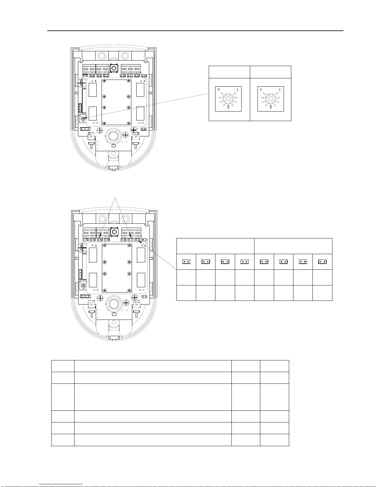
Pulse Counter (2, 3 and 4 pulses selectable)
Range-controlled radar(RCR) technology
Selectable EOL resistance.
Temperature compensation for the sensitivity of the PIR.
Introduction
The AD37 is a dual technology motion sensor combine range-controlled radar(RCR) technology with a passive infrared (PIR)
system to increase false alarm immunity by allowing then to sense human-sized objected with a specified range. Both the RCR
and PIR systems must be trigged to set off an alarm.
The AD37 is compact, attractive and easy to install, it can be mounted indoors on a wall or in a corner.
The AD37 is ideal for commercial, office and residential applications.
The AD37 emits no radiation and is harmless to humans & animals.
The AD37 reduces false alarms to a very low level due to its effective elimination of background noises and nuisance stimuli.
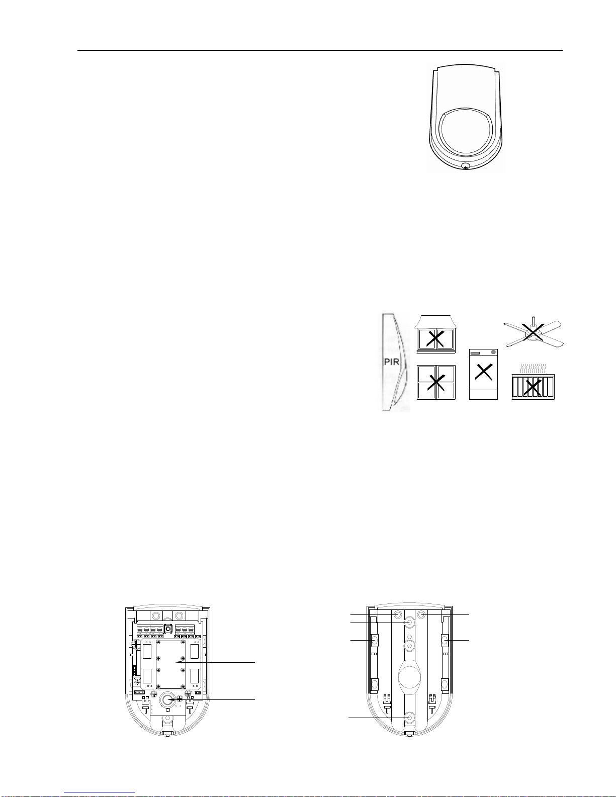
Mounting Location
The AD37 is designed for indoor use. It should not be mounted near to large
metal objects or on metal surfaces. It needs to be mounted on a wall or in a
corner at a height of approximately 2-2.5meters for the best general
coverage in an average room. The detector has been designed to avoid false
alarms, nevertheless, it is best to avoid looking directly at sources of heat
such as fires and boilers, and always try to keep away from a window. A
PIR can look at a radiator but should not be sited above one.
Please note that the microwave sensor can penetrate walls, floors and
ceilings.
When installing multiple sensors:
-DO NOT mount sensors facing each other.
-DO NOT mount facing moving or vibrating objects. (fans, pulleys, conveyor belts)
-Mount them at least 40 feet(12.2m)apart.
-Mounting sensors back to back is not recommended, but if an application requires such mounting, use the 13 ft (4.0m)range,
mount at least 1 ft(0.3m) apart, and walk test the installation to ensure proper operation.
Do not site a PIR where its field of view may be obstructed (e.g. by curtains). Also note that PIRs work best when sensing
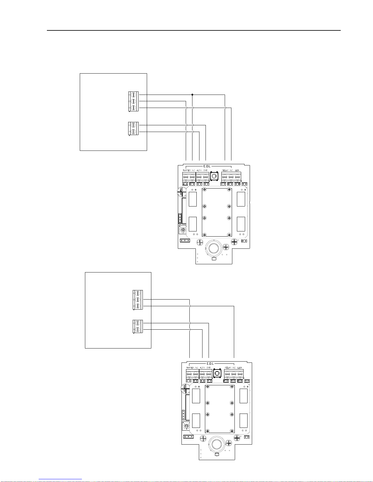
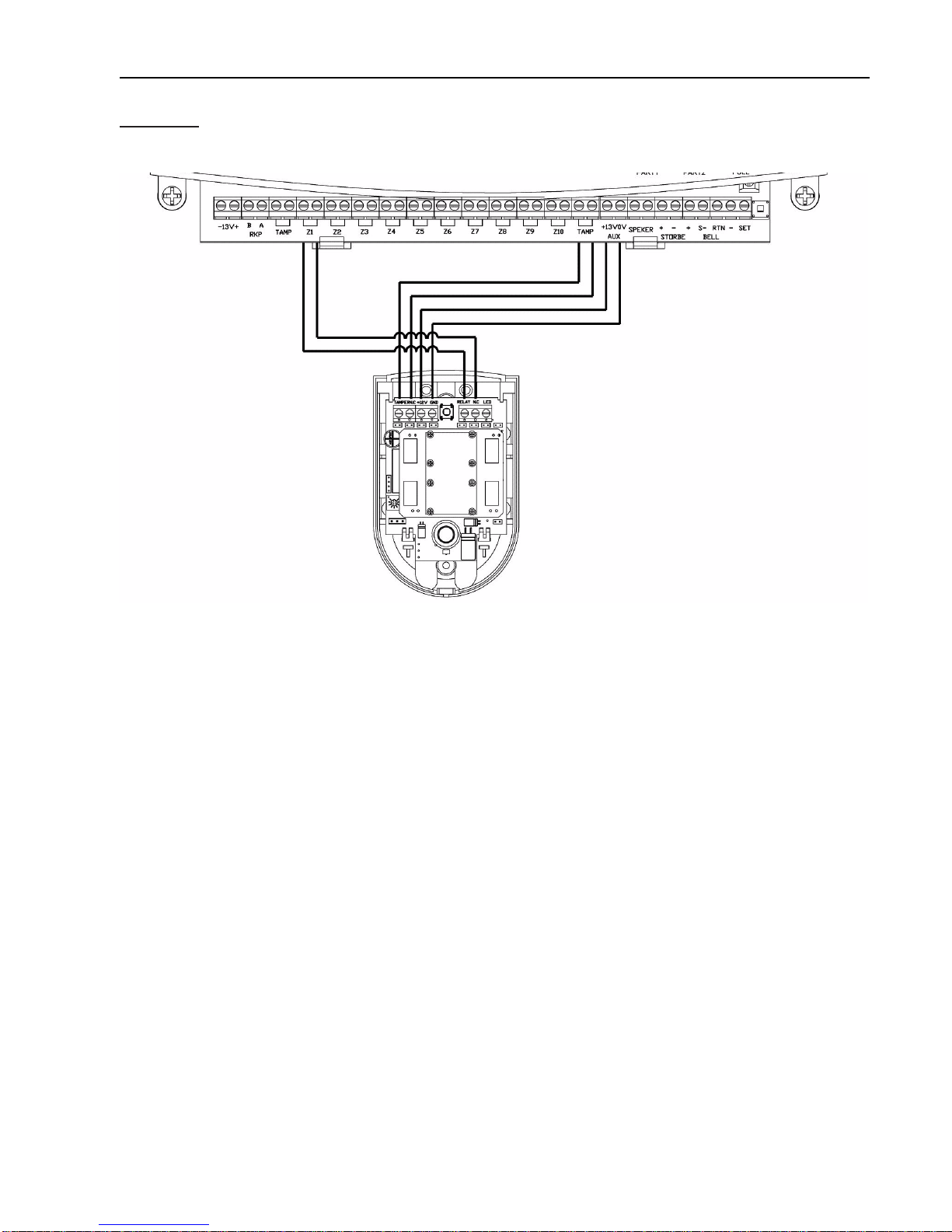
movement across rather than along their detection beams. You need to consider the need to wire these units back to the Control
Unit.
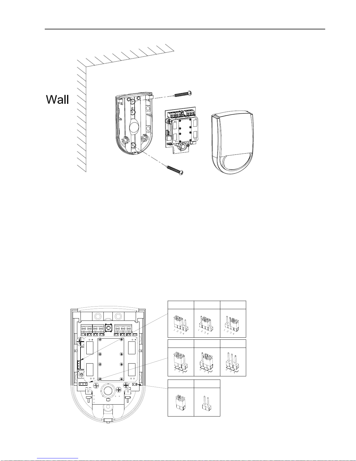
Mounting the detector
1. Remove and retain the screw from the bottom of the PIR and lift off the cover.
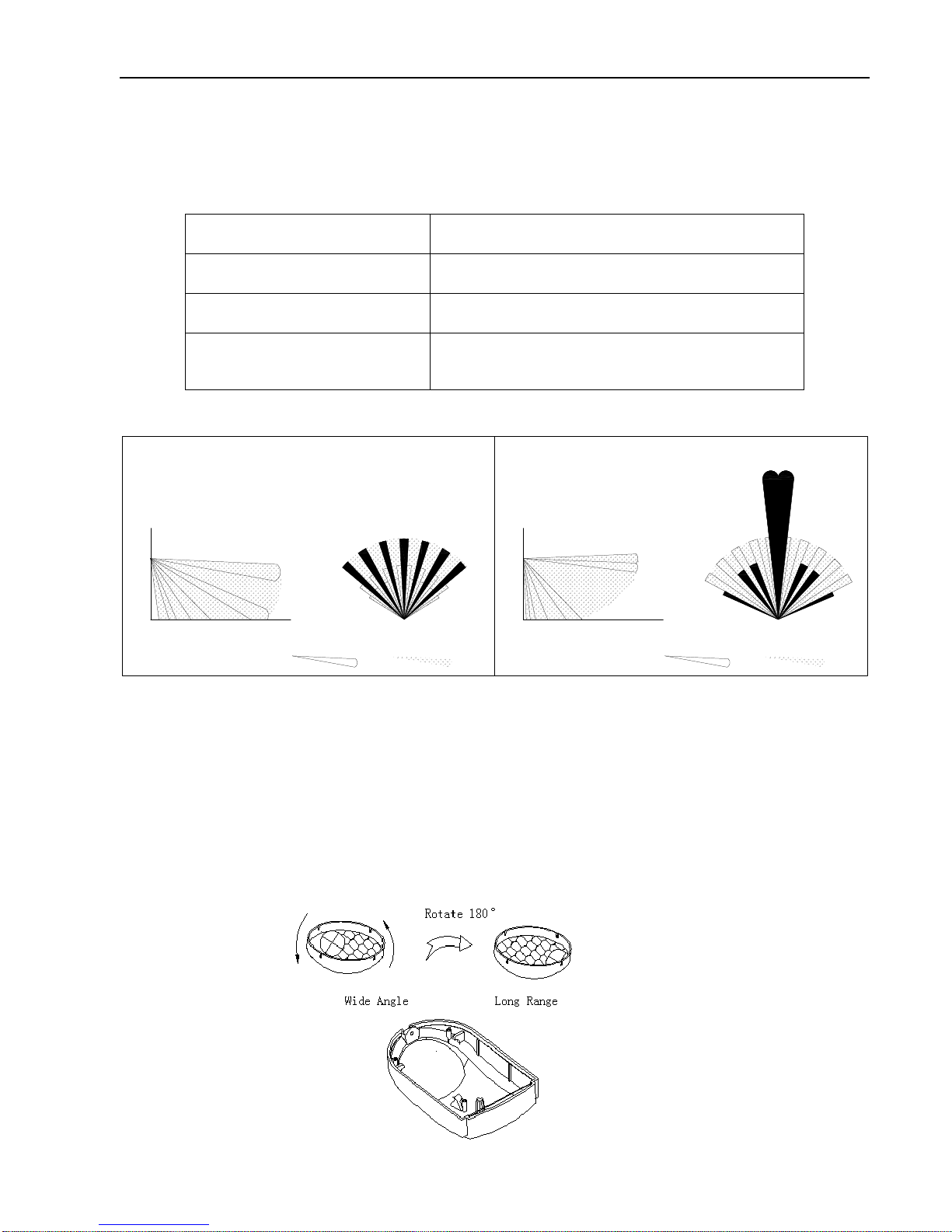
2.
Carefully remove the electronic module from its retaining clips, ensuring not to touch the pyroelectric sensor and RCR
Sensor (Illustration 1).
FAN
Illustration 1
Illustration 2

AD37 G2 PIR Dual Tech Manual
Challenger_AD37 _Instructions_Rev01
3. Install PIR on wall as below figure
4. Hold the base of the PIR in the chosen position, ensuring that the front of the PIR will face
towards the center of the protected area, mark and drill two fixing holes in the wall.
Choose one of the cable entry holes “C” and make a third hole in the detector base. Put one end of the wire through this
hole “C”, then secure the PIR to the wall.
5. Replace the electronic module into the retaining clips, ensuring that it is correctly positioned and firmly seated.
6. If required, select the LED “ON” or “OFF” option and the sensitivity (pulse count)of PIR by setting the corresponding
jumpers on the electronic module. Note that Pulse2 option is more sensitive than the pulse 4 option. Pulse 2 option is used
when it is necessary to activate an alarm on the first detected pulse, or in high security installations – where fast “catch”
performance is of greatest importance. Pulse 3 or 4 settings provides improved protection against false alarms caused by all
types of environmental disturbances. (Illustration 3)
7. Jumper J14 for walk test of part company. Selected 1-2 position for PIR testing, Selected 2-3 position for range-controlled
radar(RCR), Selected 3-4 position for PIR and range-controlled radar(RCR) testing together. (Illustration 3)
8. Range-controlled radar (RCR) provides trimmer (VR2) to select the detection range. (Illustration 4). You need to set VR2
as close to the intended coverage range as possible. Overshooting the coverage area may cause false alarms.
9. For disable EOL function do not set jumpers of alarm and tamper.
(
Illustration 6)
10. Enable EOL function and selectable EOL resistance.
Refer to the chart below for the correct endof line resistance, and set jumpers of
alarm and tamper. (
Illustration 5、Illustration 7 and Illustration 8) Please Note: for Grade 2 EOL function is required
11.
Illustration 3
IR&MW
MW
IR
LED OFFLED ON
Pluse Count 2 Pluse Count 3 Pluse Count 4

AD37 G2 PIR Dual Tech Manual
Challenger_AD37 _Instructions_Rev01
Illustration 4
Illustration 5
Control panel types available on this model.
Type Control Panel Alarm Tamper
1 Honeywell, Ademco Microtech 1K 1K
2
Challenger (Force-48),
Scantronic, Menvier,
Pyronix PCX (12, 22, 44, 128 VID), Texecom,
Castle CareTech G3 Plus.
4K7 2K2
3 DSC 5K6 5K6
4 Guardtec 6K8 4K7
5 Pyronix Matrix, PCX SMS, 134, 256. 4K7 4K7
Max Min
E.O.L
Black Red Blue YellowYellow
Blue
Red
Black
Alarm
Tamper
1K
4K7
5K6
6K8
4K7 5K6 2K2 1K

AD37 G2 PIR Dual Tech Manual
Challenger_AD37 _Instructions_Rev01
Wiring Diagram
1).
Use this wiring configuration when connecting normally closed detection devices to the zone using 6-Wires. (
Force-48
illustrated)
Illustration 6
2). Fully Supervised (
Force-48
illustrated)
Illustration 7
Tamper E.O.L resistor=2K2
Alarm E.O.L resistor=4K7
Tamper E.O.L resistor=N.P
Alarm E.O.L resistor=N.P
AUX
Zone
0V
+13V
A
T
C
C
T
A
+13V
0V
E.O.L
Zone
AUX

AD37 G2 PIR Dual Tech Manual
Challenger_AD37 _Instructions_Rev01
3). Use this wiring configuration when connecting normally closed detection devices to the zone using 6-Wires. (
Force-10
illustrated)
Please Note: If more than one tamper is to be wired Force 10 system then the TAMP circuit will need to be wired in series and not parallel.
Illustration 8
12. Connect the wires in accordance with the terminal block connections.
–12V+ Connect to a regulated D.C. power source, observing correct polarity.
TAMP Connect to a Tamper or 24 Hr. zone, NC in the control panel. Note these are normally closed switch contacts
which open when the tamper opens.
RELAY Connect to an Alarm zone, NC in the control panel. Note these are normally closed relay contacts which
open when the detector alarms.
Walk Testing
A. Apply power and allow 3 minutes for warming up and stabilizing.
B. Adjust the vertical pattern angle per Fig.1 below.
C. Walk slowly across the field of view (in opposite directions) and observe the LED – it lights whenever you enter or exit a
sensitive beam. Allow 2 seconds between each test for the unit to stabilize.
(See Understanding the LED)
D. After testing, the LED can be disabled to prevent unauthorized tracing of the coverage pattern. To disable the LED,
remove the jumper from the left and middle pins of the LED selector (ON) and place it across the middle and right pins
(OFF).
Tamper E.O.L resistor=N.P
Alarm E.O.L resistor=N.P

AD37 G2 PIR Dual Tech Manual
Challenger_AD37 _Instructions_Rev01
Understanding the LED
The multi-color LED located on the bottom of the sensor indicates the status of the unit as described in the following table.
Table1:LEDs
Lens Arrays
Fig.1
LENS can be adjusted to suit your needs by simply rotating the angle of the lens 180∘to change from wide angle version
(Ex-factory version) to long range version if required.
WIDE ANGLE LONG RANGE
Angle: 105
o
x 110
o
Angle: 5
o
x 5
o
Distance: 12m Distance: 14m
Zone Number: 64 Zone Number: 8
Default Setting – Ex Factory Default Setting + 180
o
LED
Status
Yellow
RCR detection only(no alarm)
Green
PIR detection only (no alarm)
Red
PIR and RCR detection. The sensor is in alarm and the relay
has switched
PIR RadarRadarPIR
Long Range
Side View
Top View
Wide Angle
Top View
Side View
(Ex-factory Version)

AD37 G2 PIR Dual Tech Manual
Challenger_AD37 _Instructions_Rev01
Specifications
Operating Voltage 10 - 15V D.C.
Typical Current 27mA
Maximun Current 30mA
Alarm Output Normally closed dry contacts (0.5A/24V) with 15Ωresistor in series
Tamper Output Normally closed dry contacts (0.5A/24V)
Alarm Period 2-3 seconds
Pulse Count 3 position selector2,3 and 4 pulse operation
LED Walk test enabled and disabled with internal link
Detector Dual Element low noise Pyroelectric sensor, Range-controlled radar
Coverage 90∘
Range Up to 12 meters
Operating Temperature 0 - 50℃
Due to our policy of continuous improvement we reserve the right to change specification without prior notice. Errors
and omissions accepted. These instructions have been carefully checked prior to publication. However, no
responsibility can be accepted by Challenger Security Products for any misinterpretation of these instructions.
Distributed by:
CHALLENGER SECURITY PRODUCTS
10 SANDERSONS WAY, BLACKPOOL, FY4 4NB
Email: enquiries.challenger@adivision.co.uk
Website: www.challenger.co.uk
Table of contents
Other Challenger Accessories manuals