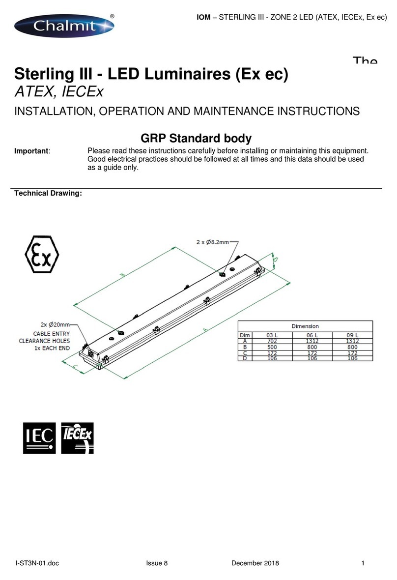
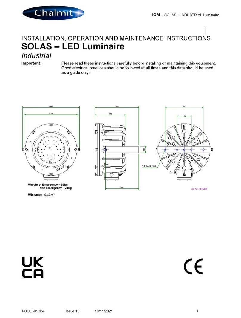
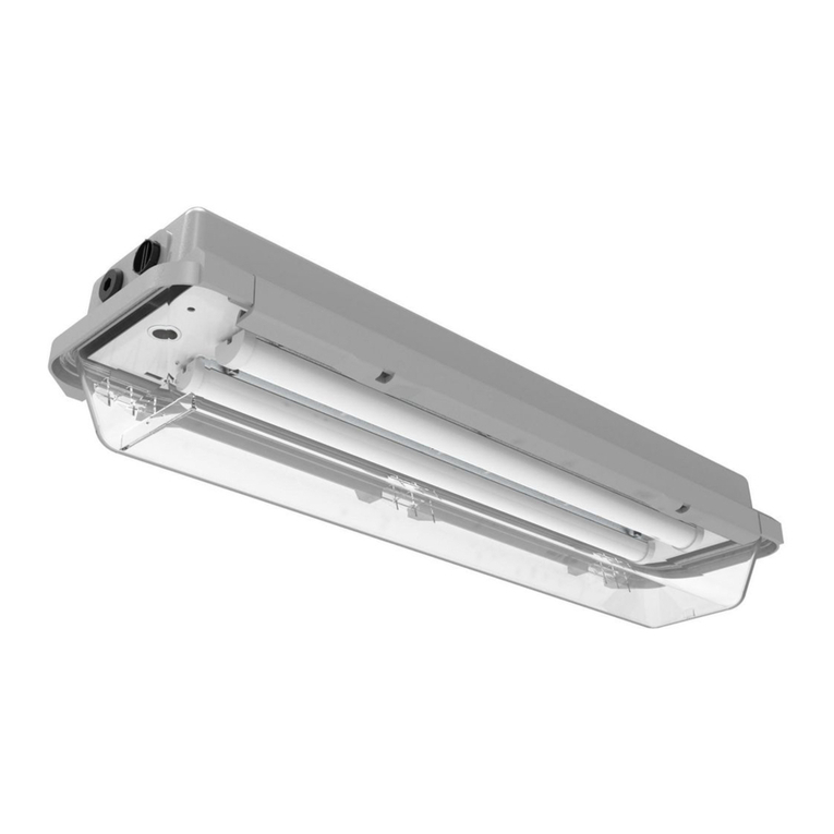
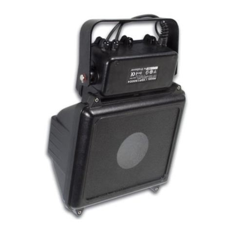
Chalmit NexLED Manual

I-NELE-11.doc Issue 05 18/07/2018 1
NEXLED EMERGENCY (IEx)
ENGLISH
INSTALLATION, OPERATION AND MAINTENANCE INSTRUCTIONS
NexLED – Emergency Bulkhead Luminaire
Important: Please read these instructions carefully before installing or maintaining this equipment.
Good electrical practices should be followed at all times and this data should be used
as a guide only.
168
99
300
205
2 x M20
Entries
Type Of
Protection
Ex e ib mb (Increased safety, intrinsic safety, encapsulation)
Protection
Standards
ABNT NBR IEC 60079-0, 60079-7, 60079-11, 60079-18, 60079-1.
Area of
application
Zone 1 and Zone 21 areas to EN/IEC 60079-10-1 and 60079-10-2.
Installation EN60079-14
Certificate IEx 15.0299
Equipment
Coding
Ex e ib mb IIC T4 Gb -45oC ≤ Ta ≤ +55oC
Ex db e ib mb IIC T4 Gb (when fitted with flameproof
isolation switch).
Standard product -20°C to +55°C
Low Temp version down to -45°C Add
suffix /LT to Catalogue Code
Ingress
Protection
IP66/67
Laser safety Class 1 LED product

I-NELE-11.doc Issue 05 18/07/2018 2
NEXLED EMERGENCY (IEx)
ENGLISH
1.0 Introduction
The Chalmit NexLED emergency brings to hazardous areas the very latest in lighting technology. It is a compact
light source that uses ultra bright light emitting diodes to provide light from mains power. The LEDs are
maintenance free and can last up to 80000 hours or more. They are housed in an impact and corrosion resistant
marine grade aluminium enclosure with a toughened glass lens. The control gear is electronic with regulated
lamp output. The LEDs work equally well at very low temperatures as they do at high and produce a product with
very low overall power consumption. When the Nexled is specified for low temperature it should be fitted with a
battery pack heater to enable the battery pack to be kept at an optimum temperature for maximum reliability and
duration. The LEDs also emit no ultra-violet light and no forward heat.
The product is available with 2 or 6 LED Array and an accessory kit is available for exit signs.
Led 2 x 1
W
(/201) 6 x 1
W
(/801)
Voltage range AC 110 - 254V
Frequency range Hz 50/60/0Hz
Power Watts 220-254V 7W (15W) 11.1W (20.6W)
Current Amps 220-254V 51mA (82mA) 71.6mA (101.5mA)
Power Watts 110-130V 6W (15W) 10.6W (20.8W)
Current Amps 110-130V 52mA (127mA) 100.7mA (193.8mA)
* Figures brackets represent values when heater is in operation
The safety limit for surface temperature (T rating) is +/-10% on the rated voltage. Equipment should not be
operated continuously at more than +10/-10% of the rated voltage of the control gear.
Batteries 4.2V 4Ah NiCd (Battery Pack is disconnected for transportation)
Emergency Duration 90 minutes duration for the 6 x 1 Watt and
3 hours duration for the 2 x 1 Watt
Emergency Output 100%
Power Factor 0.85 minimum
EMC EN 61547 EN 55015
Over voltage 400V ac for 1 min
Looping The looping current rating is 16A. 4mm² terminals are standard (6mm² wiring
can be used in the terminals in accordance with the luminaire certificate)
Tamb Storage -40°C to +50°C
Storage Luminaires are to be stored in cool dry conditions preventing ingress of moisture
and condensation.
LED The LED used in the Nexled is the latest technology and is a class 1 LED
product.
Fuse and MCB Ratings Current consumption of an 6 LED unit is 66mA and for a 2 LED unit 49mA. It is
recommended that for selection of MCB's users should consult the MCB
manufacturer. MCB ratings can vary depending on the manufacturer and type
and the size of the installation, i.e. impedance of conductors, however type ‘C’
breakers are usually suitable. The electronic control gear has an inrush current
SPECIAL CONDITIONS FOR SAFE USE
None

I-NELE-11.doc Issue 05 18/07/2018 3
NEXLED EMERGENCY (IEx)
ENGLISH
of 12A for less than 1ms on 230V. These figures are worst case with low resistance connections with short
cables and low impedance supplies.
2.0 Storage
Luminaires and control gear boxes are to be stored in cool dry conditions preventing ingress of moisture and
condensation. Any specific instructions concerning emergency luminaires must be complied with.
Diagram showing fully specified circuit with optional heater.
3.0 Installation and Safety
3.1 General
There are no health hazards associated with this product whilst in normal use. However, care should be
exercised during the following operations. Installation should be carried out in accordance with ABNT NBR IEC
60079-14 or the local hazardous area code of practice, whichever is appropriate, and fitting of specified
insulating material to be adhered to where a specific fire resistance rating is required. In the UK the requirements
of the 'Health and Safety at Work Act' must be met.
Handling and electrical work associated with this product to be in accordance with the 'Manual Handling
Operations Regulations' and 'Electricity at Work Regulations, 1989'. Your attention is drawn to the paragraphs
(i) 'Electrical Supplies', (ii) 'Electrical Fault Finding and Replacement' and (iii) 'Inspection and Maintenance'.
The luminaires are class 1 and should be effectively earthed. Certification details on the rating plate must be
verified against the application requirements before installation.
The information in this leaflet is correct at the time of publication. The company reserves the right to make
specification changes as required.
3.2 Tools
No 1/2 Philips/Pozidriv/T20 Torx screwdrivers
3mm and 5mm flat blade screwdriver
Spanners for installing cable glands.
Pliers, knife, wire Strippers/cutters.
EARTH
LIVE CONSTANT
NEUTRAL
6 or 2 x 1W LED
ELECTRONIC
CONTROLLER
LIVE SWITCHED
BATTERY
PACK
HEATER
THERMISTOR

I-NELE-11.doc Issue 05 18/07/2018 4
NEXLED EMERGENCY (IEx)
ENGLISH
3.3 Electrical Supplies
The standard unit is rated for a nominal 110V-254V AC 50/60/0Hz. A maximum voltage variation of +6%/-6% on
the nominal is expected. (The safety limit for T rating is +10%). The lamp supply is regulated therefore the light
output over the supply range is constant.
The battery pack red wire should be the last connection made prior to energising supply power.
3.4 LED Array & Driver
This product is fitted with LED array that can last in excess of 80000 hours. Therefore in many applications
replacement of the LED array will be unnecessary. If replacement is required ensure mains supplies are isolated
before commencing work.
Open the front cover by unscrewing the 4 cheese head screws, and hang to the side.
Gain access to control gear & wire connections below the LED array, loosen the 4 Trox head screws, slide Array
plate out and hang to the side.
Disconnect the battery red wire and insulate bare conductor in a spare terminal.
Disconnect the flying lead wires from LED array at the terminal block.
Assembly is the reverse of disassembly.
The driver and batteries may be replaced, ensure the correct parts are ordered and that the cables are
reconnected correctly. Also ensure that the gasket/glass mating surfaces are clean and cables are not trapped.
Prior to any work internally the Red Battery wire should be disconnected and insulate bare conductor in
a spare terminal.
3.5 Mounting
Luminaires should be installed where access for maintenance is practical and in accordance with any lighting
design information provided for the installation. Mounting is by 4 holes in the base of the body casting external to
the gasket. These should be secured with lock washers or self-locking nuts and bolts and are accessed by
removing the front cover. Any mounting attitude may be used.
3.6 Cabling and Cable Glands
3.6.1 Cables
The maximum conductor size is 4mm². Internal earth point is provided next to the main terminal block. 300/500V
cable ratings are adequate and no special internal construction is necessary. The standard looping cable size is
up to 4mm². The selection of cable size must be suitable for the fuse rating. Terminals are supplied with
suitability for looping. Where looping is used the maximum current is 16A. Terminals are accessed by removing
the front cover and LED module. Maximum cable temperature rise is 20oC above ambient.
3.6.2 Cable Glands
The installer and user must take responsibility for the selection of cables, cable glands and seals. Three tapped
cable entries are provided, two with a plug and seal suitable for permanent use, the other with a travelling plug
not suitable for use in service. Sealing plugs are similarly rated and a tool must be used for their removal. Cable
entries are M20x1.5. Cable glands and sealing plugs must have “Generation E” approval.
The cable and gland assembly when installed must maintain a minimum of IP66/67 rating.
The cable glands must be suitable for the application. Where brass cable glands are used in a corrosive
environment, cadmium or nickel plating should be used.
3.8 Emergency Operation
When there is a disruption to the mains supply the Nexled will switch over to battery backup; as there is no
difference in light output this will be signalled by one blink at switchover. Following a full discharge, the LEDs will
blink periodically as the batteries regenerate.
It is recommend that the battery pack is charged for a 24 hour cycle, then fully discharged and re-charge so that
the full duration can be achieved. However if the battery pack has been fully discharged an additional cycle may
be required.

I-NELE-11.doc Issue 05 18/07/2018 5
NEXLED EMERGENCY (IEx)
ENGLISH
3.9 Battery Maintenance
The battery pack is a 4.2V 4Ah NiCad 4 cell pack. Periodic testing allowing full discharge will enable the cells to
remain in a healthy condition. Should the battery pack need to be replaced spares may be ordered from Chalmit
Lighting. The battery assembly must be protected from damage and water ingress then removed from any
potentially hazardous area as soon as practical.
The luminaire must not be operated without the battery connected. If the battery is removed and not replaced
the control gear supply must be disconnected at the mains terminal block and secured. Care must be taken to
connect the positive and negative terminals correctly.
3.9.1 Low temperature operation with battery heater
At temperatures near 0°C ambient the battery heater will switch on. This enables the batteries to be maintained
within their optimum temperature range down to -45°C.
4.0 Inspection and Maintenance
Visual inspection should be carried out at a minimum of 12 monthly intervals and more frequently are severe;
refer to ABNT NBR IEC 60079-17.
4.1 Electrical Fault Finding and Replacement
Any fault finding must be done by a competent electrician with the luminaire isolated and, if carried out with the
luminaire in place, under a permit to work. Fault finding is by substitution with known good components.
5.0 Routine Maintenance
Visual tests and checks should be carried out at intervals described by the appropriate regulations, ABNT NBR
IEC 60079-17, and should include the following:
Check that the LEDs are working.
Check for mechanical damage/corrosion.
Check for loose connections including earthing.
Check for undue accumulations of dust or dirt.
Verification of tightness of fixing, glands, blanking plugs etc.
Check for unauthorised modifications.
Check condition of enclosure gasket and fastenings.
Check for any accumulation of moisture.
Periodic inspection of the enclosure seal should be carried out to ensure that the seal is sound.
If the luminaire has been subject to abnormal conditions, for example, severe mechanical impact or chemical
spillage, it must be de-energised until it has been inspected by an authorised and competent person. If in doubt,
the unit should be returned to Chalmit for examination and, if necessary, replacement.
Before re-assembling, all connections should be checked and any damaged cable replaced.
Prior to any work internally the Red Battery wire should be disconnected and insulate bare conductor in
a spare terminal, and should be the last connection made prior to closing the unit.
6.0 Disposal of Material
Any disposal must satisfy the requirements of the WEEE directive [2012/19/EU] and therefore must not be
treated as commercial waste. The unit is mainly made from incombustible materials. The control gear contains
plastic resin and electronic components. All electrical components may give off noxious fumes if incinerated.
6.1 Battery Disposal
Nickel cadmium batteries are defined as 'controlled waste' under the hazardous waste regulations and the
person disposing needs to observe a 'duty of care'.
Batteries can be returned to the manufacturers for recycling. They must be stored and transported safely and
any necessary pollution control forms completed prior to transportation. Take care to fully discharge batteries
before transporting, or otherwise ensure that there can be no release of stored energy in transit. For further
details refer to our Technical Department

I-NELE-11.doc Issue 05 18/07/2018 6
NEXLED EMERGENCY (IEx)
ENGLISH
To comply with the Waste Electrical and Electronic Equipment directive 2012/19/EU the
apparatus cannot be classified as commercial waste and as such must be disposed of or
recycled in such a manner as to reduce the environmental impact.
Table of contents
Other Chalmit Lantern manuals
Popular Lantern manuals by other brands

IKEA
IKEA STRALA J2025 manual
Timeguard
Timeguard CLLED44PIRB Installation & operating instructions

J D Williams
J D Williams PD531 Assembly instructions

LIVARNO LUX
LIVARNO LUX 43174 Operation and safety notes
GOAL ZERO
GOAL ZERO Lighthouse Micro Charge user guide

HAMPTON BAY
HAMPTON BAY 32300-008-4pk Use and care guide
