manuals.online logo
Brands
  1. Home
  2. •
  3. Brands
  4. •
  5. UFO
  6. •
  7. Lantern
  8. •
  9. UFO Cube DMX Specification sheet

UFO Cube DMX Specification sheet

PRODUCT USER GUIDE
Cube Illuminator
PLEASE READ THIS USER GUIDE BEFORE INSTALLING, OPERATING
OR PERFORMING MAINTENANCE ON THE ILLUMINATOR UNIT
E357731
Rev: C2
Thank you for purchasing this UFO illuminator/luminaire.
To ensure that the illuminator is set up optimally and gives a long service life, please read this
user guide before installing, operating or performing any maintenance on the unit.
Please keep this User Guide for future reference. This User Guide is laid out in three sections
Installation -details on how to connect your luminaire
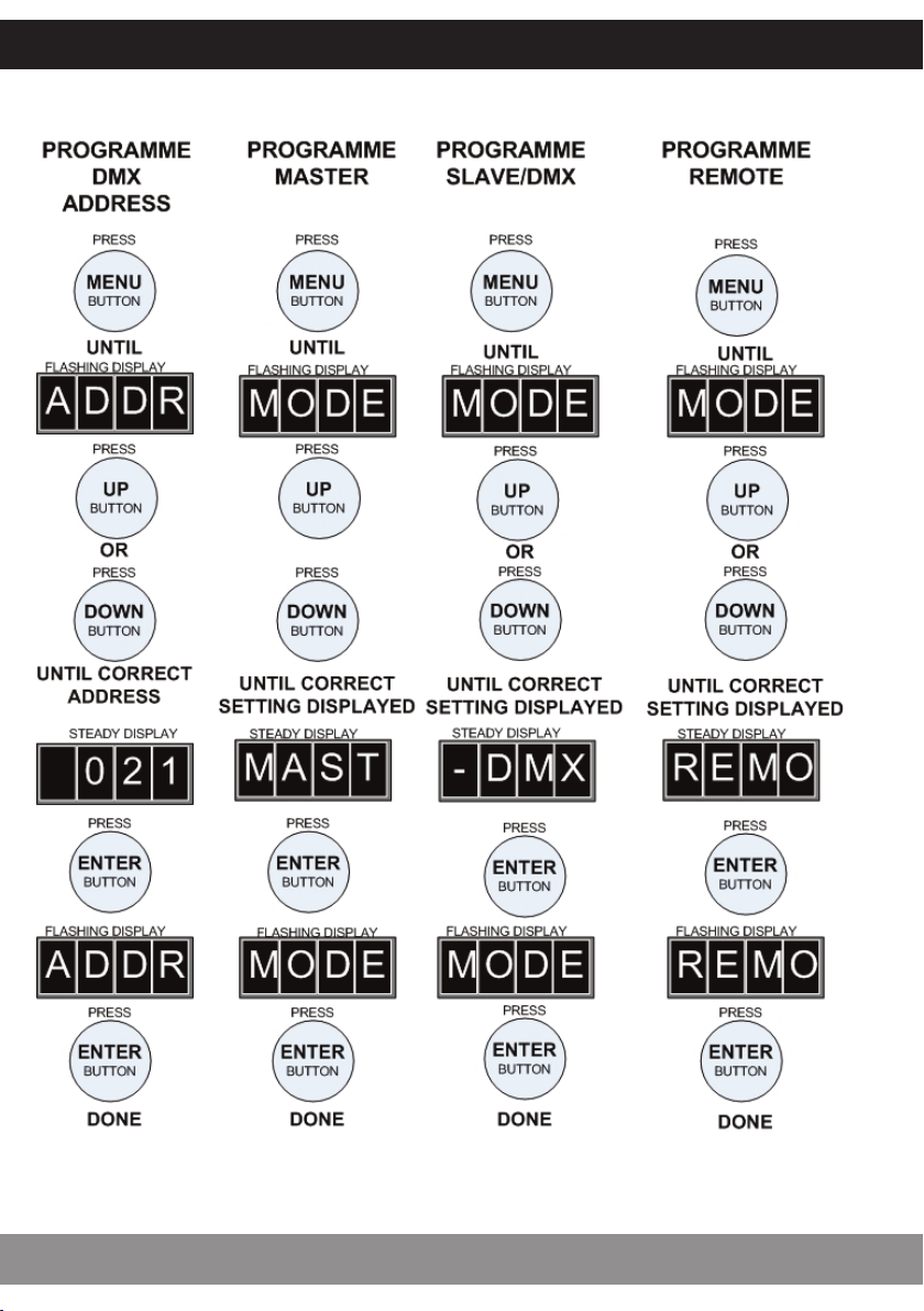
Operation - details how to programme and set up your luminaire
Maintenance - maintenance log, troubleshooting guide, technical specification
MODELS COVERED BY THIS USER GUIDE
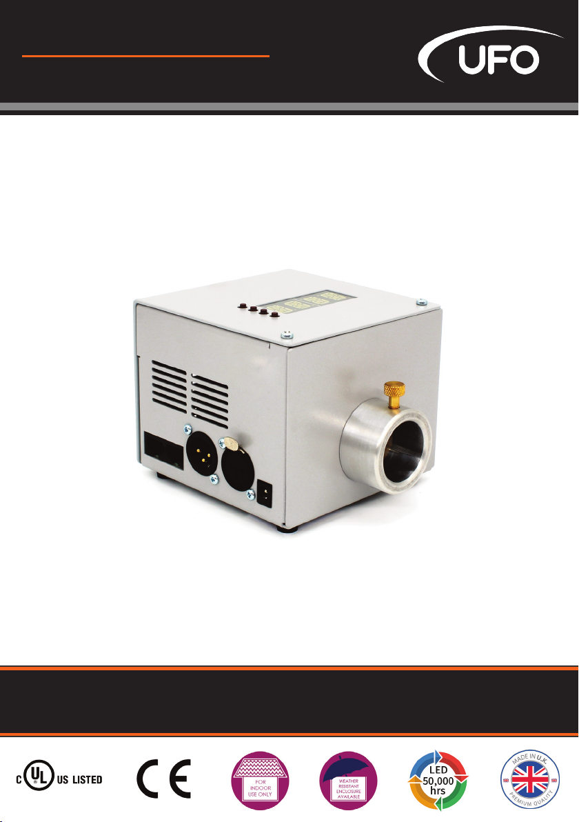
UFO Cube DMX
UFO Cube DMX-R
IMPORTANT
This product must be installed in accordance with the applicable installation code, by a person
familiar with the construction and operation of the product, and the hazards involved.
These illuminators are not mains dimmable.
The LED array in this illuminator is not replaceable. When it reaches end of life the whole unit
must be replaced.
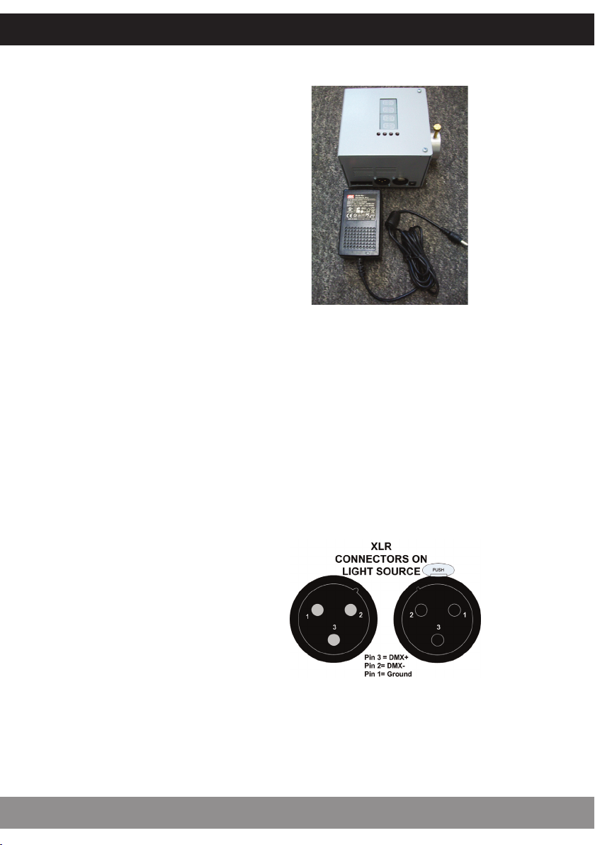
Type Y Attachment: If the external flexible cable or cord of this luminaire or associated
PSU/driver is damaged, it shall be exclusively replaced by the manufacturer or his service agent
or a similar qualified person to avoid a hazard.
Location: Do not locate this illuminator closer than 200mm from any flammable surface.
Clearance / Ventilation: It is imperative that a gap of 200mm is le around the unit. This is to
allow air to circulate and prevent overheating. The location must have free ventilation and must
not have an ambient temperature higher than that specified for the luminaire.
Mounting: This luminaire comes with an integral mounting plate for securing the unit to a
vertical or horizontal surface. Refer to the instruction sheet supplied with the plate.
Warning: Never look directly at the luminaire through the fiber port of the illuminator.
Warning: The luminaire should be positioned so that prolonged staring into the
luminaire at a distance closer than 2.7 metres is not expected.
INTRODUCTION
CUBE USER GUIDE
2
POWER SUPPLY REQUIREMENTS
The Cube illuminator is powered from a
24V DC desk top power supply unit. This
PSU is an IEC input device catering for UK,
European and USA mains supplies using
the relevant power cord.
INSTALLATION
3
UFO LIGHTING
MOUNTING PLATE INSTALLATION
This luminaire supplied with a separate
mounting plate. If using the mounting
plate refer to the fitting instructions
supplied with it.
CONNECTIONS
There are 3 connections required – the fiber port, the mains supply cable and, optionally, the
DMX control cable. The fiber port should be connected first. Connect and secure the fiber optic
connector into the 30mm diameter collar and secure using the M5 locking screw.
Connect the PSU to the DC input jack socket on the illuminator, and connect the IEC plug to the
PSU. Plug the mains plug into the electrical supply socket. Switch on power. The LED Indicator
will illuminate and the illuminator is ready for use.
If no light is produced consult the troubleshooting section.
If DMX control is required, connect up
the DMX control cables to the XLR
sockets on the rear of the illuminator.
The pin out details for the plugs are
shown right.
CONNECTIONS
As well as the standard XLR connectors for DMX connection, the Cube is also fitted with RJ45
connectors which also oer DMX capability. Details of these are below:
Pin No: 1 2 3 4 5 6 7 8
Color White
Orange Orange White
Green Blue White
Blue Green White
Brown Brown
Funcon DMX+ DMXSpare Spare Spare Spare Ground Ground
XLR = Pin 3 Pin 2   Pin 1 Pin 1
Note:
It is recommended that a 120ohm terminating resistor be connected across DMX+ and
DMX- on the last illuminator on the DMX universe or cable run
INSTALLATION
CUBE USER GUIDE
4
REAR PANEL CONTROLS
The le hand display shows a rotating line when DMX data is received.
STANDALONE MASTER MODE
In this mode the illuminator (set to Master) can be used in two ways – either as a single
independent illuminator or in a Master/Slave configuration with several illuminators connected
together using DMX cables. The Slave (set to DMX) will mimic whatever standalone
programme the Master illuminator is set to. All menu functions are available in Master mode.
Note: For Master/Slave to operate, both master & slave units must be set to address 001 only.
STANDALONE REMOTE MODE
Again in this mode the illuminator (set to Remote) can be used in two ways – either as a single in-
dependent illuminator or in a Master/Slave configuration with several illuminators connected to-
gether using DMX cables. The Master color sequences are controlled by a RF remote control and
again the Slave will mimic the Master illuminator.
DMX MODE
In this mode the illuminator (set to DMX) can be controlled either by another Cube in Master
mode or by a DMX controller.
OPERATION
5
UFO LIGHTING
CUBE REMOTE CONTROL UNIT
Descripon Details Comments
Power 2 x AAA baeries 
Range 30 metres Measured in free space, may be aenuated by
obstrucons or other RF devices
Frequency 2.4GHz Approved for use in UK, USA and Europe
With the illuminator powered up as described
above, remove the rear cover on the remote control
unit. Taking care not to touch any of the front
buttons, insert the batteries.
If you touch the remote control buttons when
inserting the batteries it WILL eect the operation of
your remote control. If you do accidentally touch any
of the buttons, remove the batteries and start again.
Once the batteries are inserted do not use the
remote control for 3 seconds.
BATTERIES
The remote control unit is matched with the illuminator at the factory.
If the remote control is not matched or an additional or replacement remote control is required
carry out the “Matching Remote to Light Source” instructions as detailed later in this guide.
If a remote control is to be removed from control of a illuminator carry out the “Unmatching
Remote to Light Source” instructions as detailed later in this guide.
FURTHER INFORMATION
OPERATION
CUBE USER GUIDE
6
REMOTE CONTROL OPERATION
No. Descripon Funcon
1 Buon Power on
2 Buon Power off
3 Color Ring Touch control all colors (white not available)
4 Indicator Indicates controller acve when buons pressed
5 Buon Increase color cycle speed
6 Buon Increase brightness
7 Buon Decrease brightness
8 Buon Decrease color cycle speed
9 Buon [Mode +] Step up through color cycle programmes
10 Buon [Mode ] Step down through color cycle programmes
10
9
8
7
6
5
4 3
2
1
MATCHING REMOTE CONTROL UNIT TO ILLUMINATOR
Remove the power plug from the rear of the Light Source, then
replace and touch button 5 within 3 seconds, the Light Source
will “blink” twice slowly indicating that the Remote Controller
is matched to the Light Source.
Once the remote is matched, follow the procedure on page 10
to put the illuminator into remote programme mode. The illu-
minator should then respond to remote commands.
UNMATCHING REMOTE CONTROL UNIT FROM ILLUMINATOR
Remove the power plug from the rear of the Light Source, then
replace and touch and hold button 5 within 3 seconds and the
Light Source will “blink” 9 times indicating that the Remote
Controller is unmatched from the Light Source.
OPERATION
7
UFO LIGHTING
Note:
More than one Light Source controlled by one Remote Controller will
eventually run out of sync with each other (color cycle mismatch)
REMOTE CONTROL MODES AND FUNCTIONS
No. Mode Brightness Speed Comment
1. Stac white Adjustable Non adjustable
Touch color ring then
mode + to enter this
mode at any me
2White and col
ors mixed Adjustable Non adjustable
Color ring control. Touch
color ring to enter this
mode at any me
3 All colors fade Adjustable Adjustable No white
4 RGBW fade Adjustable Adjustable Red, green, blue, white
5RGBW snap Adjustable Adjustable Red, green, blue, white
6 7 colors snap Adjustable Adjustable White and colors mixed
7 2 colors snap Adjustable Adjustable Red and white
8 2 colors snap Adjustable Adjustable Blue and white
9 2 colors snap Adjustable Adjustable Green and white
10 1 color flash Adjustable Adjustable Red
11 1 color flash Adjustable Adjustable Blue
12 1 color flash Adjustable Adjustable Green
13 1 color flash Adjustable Adjustable White
14 All colors
snap/fade Adjustable Adjustable Random
Mode Buttons – Do not work in a loop, i.e. touching the mode+ button will not eventually bring
you back to mode 1. To revert to mode 1, either touch mode – button repeatedly to step back
up through the mode numbers, or touch color ring then mode+
Color Ring –The color ring can be used to select individual colors by touching the ring
and sliding your finger around the ring,
Brightness – brightness can be increased or reduced in any mode using buttons 6 & 7
Cycle Speed – speed of color cycling in modes 3 to 14 can be adjusted using buttons 5 & 8
OPERATION
CUBE USER GUIDE
8
REMOTE RANGE WALK TEST
Once the illuminator is fully installed carry out a complete range walk test and record the range
in the table below.
This information is essential for maintenance purposes to determine if the range/sensitivity is
reducing and also to record dead areas within the remote control units range due to RF
obstructions and/or RF interference.
Note: Where a illuminator has more than one remote control, reduction in operating range may
be experienced when both (or multiple) remote controls are used simultaneously.
Descripon Date Max Range
Controller 1
Controller 2
Controller 3
Dead Areas
OPERATION
9
UFO LIGHTING
PROGRAMMING
OPERATION
CUBE USER GUIDE
10
PROGRAMMING
OPERATION
11
UFO LIGHTING
STANDALONE OPERATION
Prog Funcon Effect
1 Color 1 White
2 Color 2 Red
3 Color 3 Green
4 Color 4 Blue
5 Color 5 Yellow
6 Color 6 Cyan
7 Color 7 Magenta
8Snap color change between
colors 1,2,3,4,5,6,7
Display color for adjustable me (display
mer) and then snap to next color
9Snap color change between
colors 2,3,4,5,6,7
Display color for adjustable me (display
mer) and then snap to next color
10 Snap color change between
colors 1,2,3,4
Display color for adjustable me (display
mer) and then snap to next color
11 Fade color change between
colors 1,2,3,4,5,6,7
Display color for adjustable me (display
mer) and then fade slowly to next color
12 Fade color change between
colors 2,3,4,5,6,7
Display color for adjustable me (display
mer) and then fade slowly to next color
13 Fade color change between
colors 1,2,3,4
Display color for adjustable me (display
mer) and then fade slowly to next color
OPERATION
CUBE USER GUIDE
12
DMX CHANNEL OPERATION
The Cube DMX occupies 6 DMX channels as detailed below.
Channel Funcon Values
1Red 0225
2 Green 0225
3 Blue 0225
4 White 0225
5 Redundant 
6 LED & Fan 0250 on / 251255 off
Date Maintenance Undertaken
Note: A record of all maintenance MUST be kept in the table above, indicating what maintenance
was undertaken and when. This MUST be dated for warranty purposes.
OPERATION
13
UFO LIGHTING
MAINTENANCE
Problem Probable Cause(s) Remedy
Illuminator dead,
LED indicator on PSU
not illuminated
Main supply offCheck supply and reinstate
Loose mains plug Check plug
PSU faulty Replace PSU
Unit dead – LED
indicator on PSU illu
minated, LCD display
on illuminator not il
luminated
Loose DC plug Check plug
PSU faulty Check PSU output / replace PSU
Illuminator faulty Replace illuminator
Illuminator no light
output but LCD
display on illumina
tor is illuminated
If programme Mode is set to “REMO”, illu
minator may have been switched offusing
RF remote control
Switch array on using RF remote control
LED array/driver faulty Replace illuminator
RF remote controller
range reduced
Remote baeries failing Replace baeries as per user guide
Another RF device causing interference Check for another RF device in same area
RF remote control needs reseng Remove and reinsert baeries as per user guide
RF remote failing Replace remote
Illuminator receiver failing Replace illuminator
Illuminator won’t re
spond to RF
remote controller
Illuminator not in Remote mode Check mode programming and set to “REMO”
Remote baeries failed Replace baeries as per user guide
RF remote control needs reseng Remove and reinsert baeries as per user guide
RF remote failed Replace remote
Illuminator receiver failed Replace illuminator
Not responding to
DMX – no rotang
symbol on LCD dis
play
Illuminator not in “DMX”mode Check mode programming and set to “DMX”
DMX address incorrectly set Change address on illuminator or DMX controller
No DMX signal from controller Check DMX controller for correct seng
Wiring fault on DMX cables/connecons Check cable connecons and repair as necessary
DMX driver failure Replace illuminator
Not fully responding
to DMX – some but
not all colors con
trollable, no rotang
symbol on LCD
display
Illuminator address out of range – not 6
available channels on DMX controller
Change address on illuminator or DMX controller
to make 6 channels available
Not responding to
DMX – no light
output, rotang
symbol on LCD
display
Incorrect address set on illuminator or
controller Check addresses
No values set in DMX channel Check DMX controller channel values
Channel 6 value high (251255) switching
offthe array Reduce channel 6 value to <251
LED array/driver failed Replace illuminator
Poor light output on
fiber
Unit needs cleaning Clean the LED lens with a dry cloth
Clean fiber common end
Fiber port connector not plugged in
correctly
Ensure plugged in correctly and secured with
locking screw
TROUBLESHOOTING
CUBE USER GUIDE
14
TECHNICAL SPECIFICATION
15
UFO LIGHTING
Port Connector Size 30mm diameter
Fiber Type Glass / PMMA
Material/Finish Aluminum, powdercoated grey
Dimensions (L x W x H) 110mm (4.3”) x 110mm (4.3”) x 95mm (3.7”)
Weight 0.6kg
Operang Environment Indoor use IP20
Min Ambient Temp. 10°C
Max Ambient Temp. +45°C
LED Array Type Custom RGBW array
LED Array Power 35W
LED Array Model Luxeon 16 LED array
LED Array Life (L70, B10) 50,000 hours typical at 25°C
Red 615nm \ 345lm
Green 530nm \ 500lm
Blue 460nm \ 110lm
White 6500K \ 580lm
Control Funconality DMX & manual dimming
DMX Funconality User addressable to 512
DMX Channels 6 channels
Color Change
Funconality DMX, manual & remote control
RF Remote Frequency 2.4GHz
RF Remote Range 30m, depending on environment
RF Remote Power 2 x AAA baeries (supplied)
Supply Voltage 90264Vac
Mains Running Current 0.2A @240Vac
Mains Voltage VA rang 50VA
External PSU Type Meanwell, 24V, 2.5A, 60W
Fan Type Sunon, 60mm, 10dBA


DESIGN SPECIFY BUILD INSTALL
United Kingdom •United States •Germany •Europe •UAE
UFO Licht GmbH
Friendsfactory AG \Gutenbergstraße 1
85737 Munchen \ Deutschland
+49 (0)9491 955880
www.ufo-licht.de
Universal Fiber Optic Lighting USA LLC
1749 Northgate Blvd
Sarasota \FL34234 \USA
941-343-8115
www.fiberopticlighting.com
Universal Fiber Optics Ltd
Home Place \Coldstream
TD12 4DT \UK
+44 (0)1890 883416
www.ufo.lighting

Other manuals for Cube DMX

1

This manual suits for next models

1

Other UFO Lantern manuals

UFO Sirius SIRCW Specification sheet

UFO

UFO Sirius SIRCW Specification sheet

Popular Lantern manuals by other brands

WE-EF RFL540-SE LED Series Installation and maintenance instructions

WE-EF

WE-EF RFL540-SE LED Series Installation and maintenance instructions

Pro-Elec PEL01364 instructions

Pro-Elec

Pro-Elec PEL01364 instructions

olympia electronics GR-796/ST/DUO/ADR quick start guide

olympia electronics

olympia electronics GR-796/ST/DUO/ADR quick start guide

Dale Tiffany 8774 Assembly instructions

Dale Tiffany

Dale Tiffany 8774 Assembly instructions

Coleman 200A LANTERN owner's manual

Coleman

Coleman 200A LANTERN owner's manual

CREE LIGHTING VG Series installation instructions

CREE LIGHTING

CREE LIGHTING VG Series installation instructions

Eurotops Z 09553 operating instructions

Eurotops

Eurotops Z 09553 operating instructions

Ultraframe Classiclantern FABRICATION GUIDE

Ultraframe

Ultraframe Classiclantern FABRICATION GUIDE

Muller licht 57030 manual

Muller licht

Muller licht 57030 manual

Techko SJL-641 user manual

Techko

Techko SJL-641 user manual

NEO TOOLS 99-087 Translation of the original instructions

NEO TOOLS

NEO TOOLS 99-087 Translation of the original instructions

Naturally Solar 1600093 Care and use instructions

Naturally Solar

Naturally Solar 1600093 Care and use instructions

Tamlite ELITE SLS Installation & operating instructions

Tamlite

Tamlite ELITE SLS Installation & operating instructions

Orion AL 11-1141/1 Mounting and safety instructions

Orion

Orion AL 11-1141/1 Mounting and safety instructions

VIPOW URZ0020 user manual

VIPOW

VIPOW URZ0020 user manual

Gama Sonic 132i90012 instruction manual

Gama Sonic

Gama Sonic 132i90012 instruction manual

Primus 2245 Instructions for use

Primus

Primus 2245 Instructions for use

Coleman 2000000859 operating instructions

Coleman

Coleman 2000000859 operating instructions

manuals.online logo
manuals.online logoBrands
  • About & Mission
  • Contact us
  • Privacy Policy
  • Terms and Conditions

Copyright 2025 Manuals.Online. All Rights Reserved.