Champion UltraCOOL CP70 User manual

Champion Cooler
5800 Murray St.
Little Rock, AR 72209
www.championcooler.com
Portable Evaporative Cooler
Safety Rules
1. Unit must be in the Off Position and Unplugged from power receptacle when performing any mainte-
nance.
2. To reduce the risk of electric shock, plug unit into a properly grounded 120 Volt A.C., 60 Hz receptacle.
3. To reduce the risk of electric shock, install only on a circuit protected with a Ground Fault Circuit Inter-
rupter (GFCI).
4. This appliance is not intended for use by persons (including children) with reduced physical, sensory or
mental capabilities, or lack of experience and knowledge, unless they have been given supervision or
instruction concerning use of the appliance by a person responsible for their safety. Children should be
supervised to ensure that they do not play with the appliance.
WARNING: To reduce the risk of fire or electric shock, do not use this fan with any “solid-state
fan speed control device.”
110489-5
5/09
Evaporative Cooling
Evaporative cooling is an economical way to cool. Air is cooled while being drawn across wet evapora-
tive media. The movement of this fresh cooled air over the skin is what makes it feel cool. It is important
when using an evaporative cooler in an enclosed space to have adequate exhaust by opening windows,
doors, etc. Without an outlet to exhaust the air, humidity will build up in the enclosed space and the
unit will not cool adequately. It is preferable to have an opening behind the unit to bring in fresh air and
another opening across the room to exhaust and help move the air.
Read And Save These Instructions
NOTICE: This Product May Temporarily Produce An Odd Odor When First
Turned On. This Is NORMALAnd Will Dissipate AfterA Few Hours.
If you have any problems with this product, please call 1-800-643-8341
BEFORE returning it to your retailer.
Model
CP70

Cooler Installation
Install Pedestal and Casters
Unpack the unit and remove the media frame to access the pedestal and 4 cast-
ers. See the maintenance section for instructions on removing media frame.
CAUTION: Do not damage hose connecting pump to media frame. Cut
the cable ties holding pedestal to frame of unit and remove pedestal. Remove
the casters from the underside of the pedestal. To install the pedestal, turn the
unit on it’s side. Line up the bosses on the pedestal to the bosses on the base
of the unit (see fig. 1). Use the four provided screws to attach the pedestal
to the base of unit. Press the stem casters into each corner hole of pedestal,
installing the 2 locking casters on the front and the 2 non-locking on the back
side. Operation
Fill With Water
To fill this unit with water, open the water fill door and fill with a
pitcher or water hose (see fig. 2). Do Not Overfill. CAUTION:
Take care when moving unit filled with water, spillage may
occur. Unlock casters when moving. Do not tip unit.
Water Level Indicator
On the front of the unit there is an access window to view the
level of the water (see fig. 2). When the unit is full of water, the
level indicator will be at the top of the window and as the level
of the water is decreased in the unit, the indicator will lower.
Refer to the control panel in figure 3 for the following instructions.
Turning On Unit
Once the unit is plugged in, pressing the “Power” button will light up the backlight on the display and start
the unit in Fan-High mode. The pump will not start until the “Pump” button is pressed. The display will
remain backlit for 2 minutes after the last button on the control is pushed.
Pump / Cooler Operation
To operate this unit as an evaporative cooler, the unit must be filled with water and the pump powered on.
Press the “Pump” button to turn on the pump. The water drop indicator on the display will flash while the
pump is on. To operate the unit as a fan only, press “Pump” to turn off the pump.
Note: The pump will not run if the water level falls below a certain level. When the water level drops
below this level, an audible alarm will sound and the “Low Water” indicator on the display will flash on
and off. The audible alarm will stop after 60 seconds or when the “Pump” button is pushed. The indica-
tor will remain flashing until the unit is filled with water. You will need to restart the pump by pressing
“Pump” after the unit is refilled with water.
Fan Operation
Pressing the “Speed” button on the control will cycle the fan
speed from High to Mid to Low. The speed setting will be
highlighted in the display.
Oscillate Mode
Pressing the “Oscillate” button will oscillate the vertical vanes
back and forth, distributing the air side to side. The “Oscillate”
indicator on the display will be displayed when on. Press the
button again to turn off.
Timer Mode
This unit is equipped with a timer. You may set the time interval for the unit to stay on. Pressing the
“Timer” button will set the time interval in 1/2 hour increments up to 8 hours. The display will flash while
setting the time and will display constantly once it is set. The display will count down the time remaining
in 1/2 hour increments. When the time interval is reached, the unit will turn off.
FAN PUMP
TIMER
OSCILLATE
LOW
MID HIGH
COOL VENT LOW WATER
hr
Oscillate
Timer Power Speed Pump
Fig. 3
2
Water
Fill
Door
Water Level
Indicator
Fig. 2
Caster
Pedestal
Base
Fig. 1
Screw

Limited Warranty
This warranty is extended to the original purchaser of an evaporative cooler installed and used under nor-
mal conditions. It does not cover damages incurred through accident, neglect, or abuse by the owner. We
do not authorize any person or representative to assume for us any other or different liability in connection
with this product.
TermsAnd Conditions Of The Warranty
For One Year from date of purchase, we will replace any original component provided by Champion
Cooler which fails due to any defect in material or factory workmanship only.
Exclusions From The Warranty
We are not responsible for replacement of evaporative media. These are disposable components and
should be replaced periodically. We are not responsible for any incidental or consequential damage result-
ing from any malfunction.
We are not responsible for any damage received from the use of water softeners, chemicals, de-scale mate-
rial or plastic wrap.
We are not responsible for the cost of service calls to diagnose the cause of trouble, or labor charge to
repair and/or replace parts.
How To Obtain Service Under This Warranty
Contact the Dealer where you purchased the evaporative cooler. If for any reason you are not satisfied
with the response from the dealer, contact the Customer Service Department: Champion Cooler, 5800
Murray Street, Little Rock, Arkansas 72209. 1-800-643-8341. info@championcooler.com
This limited warranty applies to the original purchaser only.
Register your product online at www.championcooler.com/eac/onlineregistration-eac.htm
Maintenance
WARNING: Before doing any maintenance be sure unit is unplugged.
Drain Unit
To drain the unit, remove the media frame and remove the rubber drain stopper from the bottom of the unit
by pulling it out of the drain hole. The unit should be drained periodically to keep the water fresh. We
recommend draining the unit once a week. Drain the water from the unit when it will not be used for an
extended period.
Note: To remove the media frame, first remove the two screws located at the top of the frame (see
fig. 4). Tilt the frame back while pressing on the bottom of the frame where it says “Push” until it
snaps out, then lift out. The water distribution hose can be removed from the media frame to allow
complete separation of media frame from unit. Do not operate unit with media frame removed.
Clean/Replace Evaporative Media
The evaporative media should be cleaned twice a season or when
needed. To clean the media, rinse with clean water. Light scrub-
bing might be necessary. Be careful not to damage media. After
2 years, or when it becomes clogged, the media will need to be
replaced. To remove the media, first remove the keeper disks from
the keeper stems (see fig. 4). Remove the keeper stems from the
media and remove the media.
When replacing the evaporative media, install it so that the steeper
flute angle of the media is sloping down towards the media frame
(see fig. 4). Push the keeper stems through the media from the
back of the media frame and press the keeper disks onto the stems
to secure the media in place.
3
Keeper
Disk Keeper
Stem
Fig. 4
45°
15°
Screw

Trouble Shooting
Problem:
Cooler does not pump
water
Fan does not operate
Cause/Remedy:
• Water level is low. Fill with water and make sure Pump is activated.
• Pump may be defective. Replace pump.
• Check that unit is plugged into a 120V power receptacle.
• Check the fuse or breaker.
• If connected to a GFCI outlet, check if it is tripped.
Replacement Parts
No. Description CP70
1 Evaporative Media..................................................................................110132-3
2 Evaporative Media Frame Assembly......................................................110874-1
3 Water Tray ..............................................................................................110874-3
4 Water Distributor Nozzle........................................................................110874-4
5 Keepers (Set of 4)...................................................................................110871
6 Pump.......................................................................................................110439-1
7 Drain Plug...............................................................................................110698
8 Float Assembly.......................................................................................110873
9 Swivel Casters - Non-Locking ...............................................................110822-6
10 Swivel Casters - Locking........................................................................110822-7
11 Pedestal...................................................................................................110874-2
12 Water Distributor Tubing........................................................................110734-1
13 M4 x 12mm Pan Head S.S. Screws (Qty 2)...........................................111130
14 M4 x 12mm Truss Head S.S. Screws (Qty 4) ........................................111131
4
8
5
5
1
9
10
9
10
6
7
11
2
12
43
13
14

Champion Cooler
5800 Murray St.
Little Rock, AR 72209
www.championcooler.com
Enfriador Evaporativo Portátil
Lea y Conserve Estas Instrucciones
Reglas De Seguridad
1. La unidad debe ser Apagada y Desconectada de la electricidad cuando haga cualquier mantenimiento.
2. Para reducir el riesgo de descarga eléctrica, conecte únicamente a un receptáculo debidamente conecta-
do a tierra de 120 voltios y 60 ciclos.
3. Para reducir el riesgo de descarga eléctrica, instale únicamente en un circuito protegido por un interrup-
tor de circuito por falla de conexión a tierra (GFCI).
4. Este aparato no está destinado para el uso de personas (niños incluyendo) con capacidades físicas,
sensoriales o mentales reducidas, o la carencia de experiencia y de conocimiento, a menos que hayan
sido supervisados o dados instrucción referente al uso del aparato por una persona responsable de su
seguridad. Los niños deben ser supervisados para asegurarse de que no juegan con el aparato.
ADVERTENCIA: Para reducir el riesgo de incendio o toques eléctricos, no use este ventilador con
ningún “dispositivo de estado sólido para controlar la velocidad del ventilador.”
Modelo
CP70
Enfriamiento Por Evaporación
El enfriamiento por evaporación es una manera económica de enfriarse. El aire se enfría mientras se traza
a través de medio evaporativo mojado. El movimiento de este aire enfriado fresco sobre el piel es qué
hace la sensación fresca. Es importante al usar un enfriador evaporativo en un espacio encerrado agotar
adecuadamente el aire por medio de las ventanas, las puertas, etc. Sin una salida para agotar el aire, la
humedad se acumulará en el espacio encerrado y la unidad no se enfriará adecuadamente. Es preferible
tener una abertura detrás de la unidad a traer adentro el aire fresco y otra abertura a través del cuarto para
agotar y ayudar a mover el aire.
AVISO: Este Producto Puede Producir Temporalmente Un Olor Extraño Al
Principio. Esto Es NORMAL y Se Disipará Después De Unas Horas De Uso.
Si usted tiene algún problema con este producto, por favor llame al
1-800-643-8341 ANTES de devolverlo a la minorista.

Instalación
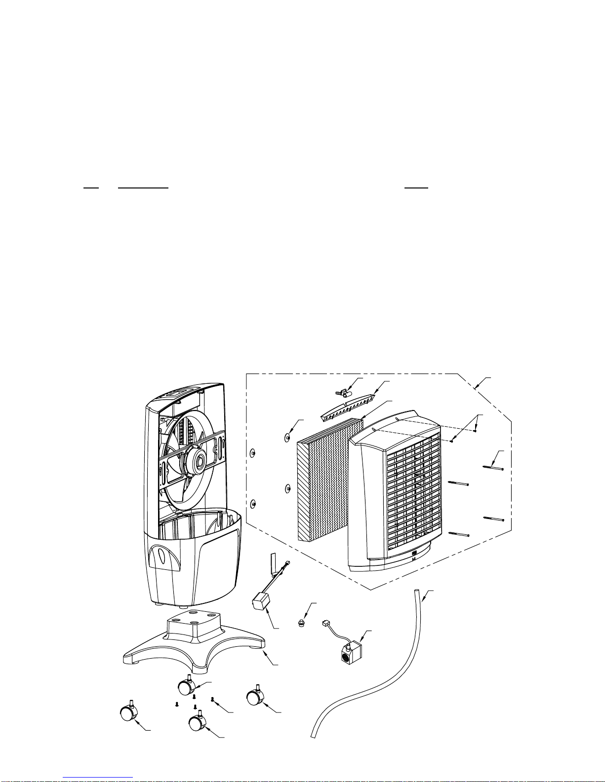
Instalar El Pedestal y Las Ruedas
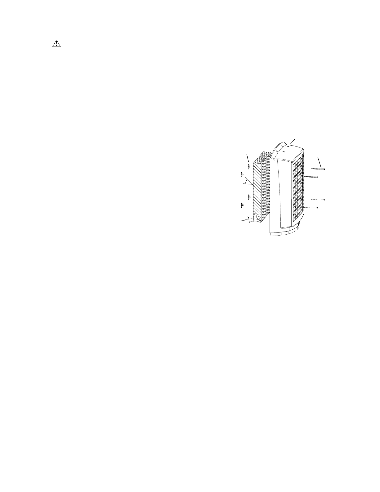
Desempaquete la unidad y quite la armazón del medio evaporativo para
tener acceso al pedestal y a 4 ruedas. Véase la sección de conservacion para
instrucciones de quitar la armazón. PRECAUIÓN: No dañe el tubo de agua
conectado a la armazón del medio. Corte las abrazaderas plásticas que sostie-
nen el pedestal al marco de la unidad y quite el pedestal. Quite las ruedas del
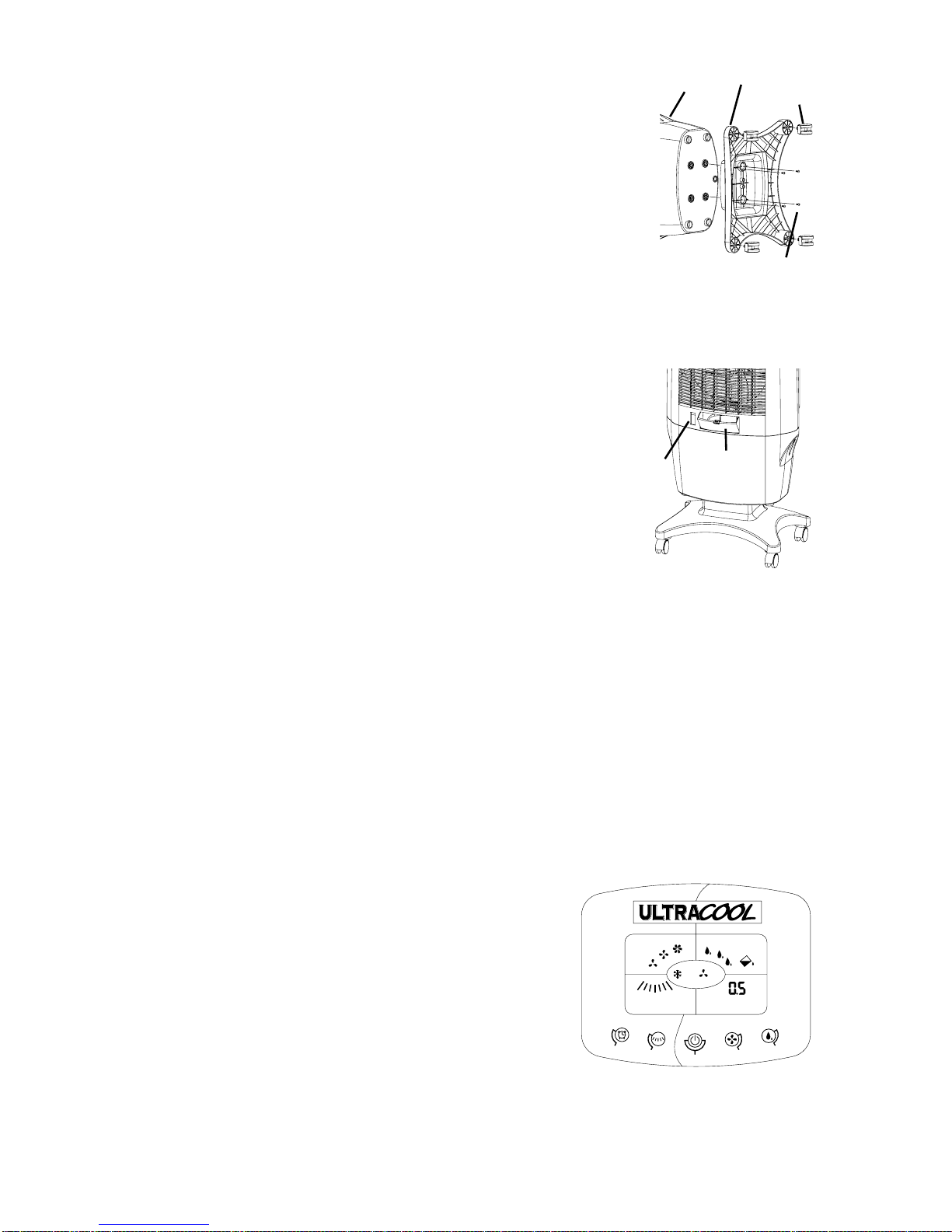
base del pedestal. Para instalar el pedestal, pone la unidad por su lado. Alinéese
a los resaltes moldeados en el pedestal a los resaltes moldeados en la base de
la unidad (véase fig. 1). Utilice los cuatro tornillos proporcionados para fijar el
pedestal a la base de la unidad. Presione los vástagos de las ruedas dentro de los
agujeros de cada esquina del pedestal. Instale los ruedas con frena al frente y los
sin frena en el lado trasero. Funcionamiento
Llenar Con Agua
Abre la puerta de agua (véase fig. 2) y llene con agua usando una jarra
o una manguera de jardín. No Sobrellene. PRECAUCIÓN: Mueva la
unidad con cuidado en caso de que se derrame. No incline la unidad.
Indicador De Nivel DeAgua
En el frente de la unidad hay una ventana de acceso para ver el nivel de
agua (véase fig. 2). Cuando está llena de agua, el indicador de nivel de
agua estará en la tapa de la ventana y cuando el nivel de agua se disminu-
ye en la unidad, el indicador bajará.
Para las instrucciones siguientes refiere a la figura 3 del panel de control.
Poner En Marcha La Unidad
Una vez que se enchufa la unidad, al presionar el botón “Power” iluminará de fondo la pantalla y pondrá
en marcha la unidad en el modo de ventilador alto. La bomba no arrancará hasta que se presione el botón
“Pump”. La pantalla quedará iluminada por 2 minutos después del presionar una botón.
Funcionamiento Del Enfriador / Bomba
Para funcionar esta unidad como enfriador evaporativo necesita llenar la unidad con agua y presionar el bo-
tón “Pump” para arrancar la bomba. El indicador de gotas de agua en la pantalla en la sección de la bomba
parpadeará cuando la bomba está prendido. Para funcionar la unidad como ventilador solamente, presione
“Pump” para apagar la bomba.
Nota: La bomba no funcionará si el nivel del agua está debajo de un cierto nivel. Cuando el nivel del agua
cae debajo de este nivel, una alarma audible sonará y el indicador de agua bajo (Low Water) en la pantalla
parpadeará intermitente. La alarma audible parará después de 60 segundos o cuando se empuja el botón
“Pump”. Después de llenar con agua, el indicador dejará de parpadear. Necesitará presionar el botón
“Pump” para poner en marcha otra vez la bomba después de rellenar la unidad con agua.
Funcionamiento Del Ventilador
Presionar el botón “Speed” en el panel de control cambiará la velo-
cidad del ventilador entre alto (High), mediado (Mid) y bajo (Low).
El ajuste de la velocidad será destacado en la pantalla.
Modo De Oscilación
Presionar el botón “Oscillate” oscilará las paletas verticales hacia
adelante y hacia atrás y destacará el indicador en la pantalla. Para
apagar la oscilación presione el botón otra vez.
Descontador De Tiempo
Esta unidad se equipa de un descontador de tiempo. Se puede fijar
el intervalo de tiempo hasta que la unidad se apaga. Presionar el botón “Timer” fijará el intervalo de tiempo
en incrementos de la media hora hasta 8 horas. Los números en la pantalla parpadeará mientras que fija el
tiempo y será sólido cuando está fija. La pantalla demuestra cuántas horas está quedado en incrementos de la
media hora. Cuando se alcanza el intervalo de tiempo, la unidad apagará.
FAN PUMP
TIMER
OSCILLATE
LOW
MID HIGH
COOL VENT LOW WATER
hr
Oscillate
Timer Power Speed Pump
Fig. 3
S-2
Puerta De
Agua
Indicador
de Nivel
de Agua
Fig. 2
Rueda
Pedestal
Base
Fig. 1 Tornillos

Garantía Limitada
La presente garantía se extiende al comprador original de un enfriador evaporativo instalado y utilizado bajo
condiciones normales. No cubre daños ocurridos por accidente, descuido o abuso por parte del propietario.
No autorizamos que ninguna otra persona o representante asuma por nosotros cualquier otra o diferente
responsabilidad en relación con este producto.
Términos y Condiciones De La Garantía
Durante Un Año a partir de la fecha de compra, reemplazaremos cualquier componente original proporcio-
nado por Champion Cooler que falle debido a cualquier defecto de material o mano de obra en la fábrica
solamente.
Exclusiones De La Garantía
No somos responsables por reemplazar los medios evaporativos del enfriador. Estos son componentes des-
echables y deben cambiarse periódicamente. No somos responsables por daños que resulten a consecuencia
de alguna falla de funcionamiento.
No somos responsable por cualquier daño producido por el uso de suavizadores de agua, productos químicos,
materiales desincrustantes o envolturas de plástico.
No somos responsables por el costo del servicio para diagnosticar la causa del problema ni por la mano de
obra necesaria para reparar y/o reemplazar piezas.
Como Obtener Servicio Bajo Esta Garantía
Póngase en contacto con el Concesionario que le vendió el enfriador. Si por alguna razón usted no queda
satisfecho con la respuesta por parte del Concesionario, comuníquese con el departamento de servicio al
cliente: Champion Cooler, 5800 Murray Street, Little Rock,Arkansas 72209. 1-800-643-8341. info@
championcooler.com.
Esta garantía limitada se aplica al comprador original solamente.
Registre su producto en línea a: www.championcooler.com/eac/onlineregistration-eac.htm
Conservación
ADVERTENCIA: Siempre desconecte el enfriador antes de procurar cualquier tipo de servicio.
Drenar La Unidad
Para drenar la unidad, quite la armazón del medio evaporativo y quite el tapón de goma del desagüe situado
en la parte inferior de la unidad. Necesita drenar la unidad periódicamente para mantener el agua dulce. Re-
comendamos el drenar de la unidad una vez por semana. Drene el agua de la unidad cuando no será utilizada
por un período extendido.
Nota: Para quitar la armazón del medio evaporativo, necesitará quitar primero los dos tornillos situa-
dos en la tapa de la armazón del medio. Incline la armazón del medio detrás mientras que presiona
la parte inferior de la armazón donde dice “Push” hasta que quite de la base de la unidad. Se puede
quitar el tubo de agua de la armazón para seperar completamente la armazón del medio de la unidad.
No funcione la unidad con la armazón quitada.
Limpiar/Cambiar El Medio Evaporativo
Debe limpiar el medio evaporativo dos veces al temporada o cuando
sea necesario. Para limpiar el medio, aclare con el agua potable.
Puede ser necesario fregar ligeramente el medio. Tenga cuidado de
no dañar el medio. Después de 2 años o cuando el medio se atasca,
necesitará reemplazarlo. Para quitar el medio, primero quite los
discos del sujetador de los vástagos del sujetador (véase fig. 4). Quite
los vástagos del sujetador del medio evaporativo y quite el medio.
Cuando reemplace el medio evaporativo, instálelo de modo que el án-
gulo más escarpado del medio esté inclinándose abajo hacia la parte
posterior de la armazón del medio (véase fig. 4). Empuje los vástagos
del sujetador a través del medio de la parte posterior de la armazón.
Presione los discos del sujetador sobre los vástagos para asegurar el
medio en el lugar.
S-3
Disco Vástago
Fig. 4
45°
15°
Tornillo

La Localización De Averías
Problema:
No Bombea El Agua
No Funcionara La Ven-
tilador
Causa/Remedio:
• El nivel de agua es bajo. Llene con agua y asegúrese de que la bomba está
activada.
• La Bomba puede ser defectuosa. Reemplace la bomba.
• Compruebe que la unidad está enchufada en un receptáculo de 120 voltios.
• Compruebe el fusible o el cortacircuito.
• Si está conectado con un enchufe de GFCI, compruebe si se desconectó.
Piezas De Repuesto
n°. Descripción CP70
1 Medio Evaporativo.................................................................................110132-3
2 Montaje De Armazón Del Medio Evaporativo.......................................110874-1
3 Canal De Agua........................................................................................110874-3
4 Boquilla De Distribuidor De Agua.........................................................110874-4
5 Equipo De (4) Sujetadores......................................................................110871
6 Bomba ....................................................................................................110439-1
7 Tapón De Goma......................................................................................110698
8 Flotador y Indicador De Agua................................................................110873
9 Rueda Giratoria - Sin Frena....................................................................110822-6
10 Rueda Giratoria - Con Frena ..................................................................110822-7
11 Pedestal...................................................................................................110874-2
12 Tubo De Agua.........................................................................................110734-1
13 M4 x 12 mm Tornillos De Cabeza Redondeada (Cantidad de 2)...........111130
14 M4 x 12 mm Tornillos De Cabeza Segmentada (Cantidad de 4)...........111131
S-4
8
5
5
1
9
10
9
10
6
7
11
2
12
43
13
14
Table of contents
Languages:
Other Champion Air Cleaner manuals
Popular Air Cleaner manuals by other brands

aldes
aldes InspirAIR Home Premium SC240 Installation and maintenance instructions

DUKART
DUKART My Air Protector Travelmap TL 30 instruction manual

Kampmann
Kampmann KA-520 XL quick start guide

Triad Aer
Triad Aer air purifier system owner's manual

NateoSante
NateoSante AIR INITIAL STYLE user guide

Giabo
Giabo GERMAGIC PAC-2302C user manual