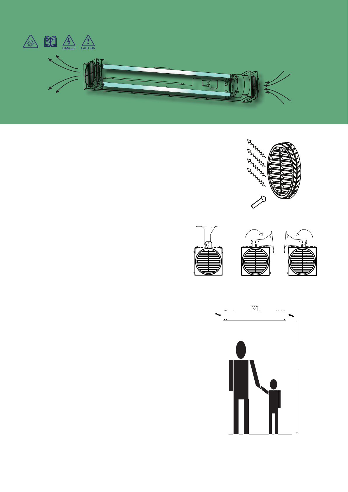
Muonio UV-L 110 User manual

PAGE 1
INSTALLATION MANUAL
UV-C air treatment is an environ-
mentally friendly and chemical-free
method of sterilizing air that does not
produce harmful byproducts during
sterilization.
MUONIO UV-C air purification sys-
tems operate safely on a timed or
constant demand basis to disinfect
the air in areas occupied by humans
and animals.
MUONIO UV-C air purification sys-
tems are particularly suitable for public
places or other spaces at a very eco-
nomical cost.
The unit uses well established UV-C
radiation which was utilised extensively
in medical, food preparation and other
professions for more than 40 years to
disinfect the air, the cleanliness of the
surfaces and to help mitigate the risk
of contracting and spreading an infec-
tion. All bacteria and viruses tested to
date (including various coronaviruses)
respond to UV-C disinfection.
The Mounio UV-L 110 ventilation dis-
infectant device is part of a broader
system range that combines ventila-
tion and climate controls.
MUONIO
UV-L 110
UV-C Disinfectant Unit

PAGE 2
CONTENTS
Description & Function
Counteracting Viruses And Bacteria . . . . . . . . . . . . . . . . . . . . . 3
Technical Data
Technical Data . . . . . . . . . . . . . . . . . . . . . . . . . . . . . 4
Technical Information . . . . . . . . . . . . . . . . . . . . . . . . . . . 4
Ordering Information . . . . . . . . . . . . . . . . . . . . . . . . . . . 4
Important Warning & Information Symbols
WARNING INFORMATION 5
Warning Symbols . . . . . . . . . . . . . . . . . . . . . . . . . . . . 5
General Installation Guidelines
Scope . . . . . . . . . . . . . . . . . . . . . . . . . . . . . . . . . 6
Locating the Unit
PRE- INSTALLATION INFORMATION 7
MOUNTING THE UNIT ON HOLLOW WALLS: 7
EYE & SKIN BURN HAZARD 7
Installation Location
Unit’s Position and Line of Sight. . . . . . . . . . . . . . . . . . . . . . . 8
Installing the Unit
Mounting The Unit on Walls or Ceilings . . . . . . . . . . . . . . . . . . . . 9
Bracket Dimensions . . . . . . . . . . . . . . . . . . . . . . . . . . . 9
General layout
Installation Procedure . . . . . . . . . . . . . . . . . . . . . . . . . 10
Terminal Identication & Description
INSTALLATION WIRING 11
Earth Connection . . . . . . . . . . . . . . . . . . . . . . . . . . . .11
Double Pole Isolation . . . . . . . . . . . . . . . . . . . . . . . . . . .11
Control Module Connections . . . . . . . . . . . . . . . . . . . . . . . .11
Power Supply . . . . . . . . . . . . . . . . . . . . . . . . . . . . . .11
Volt free SWITCHING CONTROL . . . . . . . . . . . . . . . . . . . . . .11
OPTIONAL SWITCH LIVE CONTROL. . . . . . . . . . . . . . . . . . . . .11
Service & Commissioning
SERVICE & MAINTENANCE 12
CAUTION: . . . . . . . . . . . . . . . . . . . . . . . . . . . . . . 12
UV-C Ballast . . . . . . . . . . . . . . . . . . . . . . . . . . . . . 12
Precautions with cleaning . . . . . . . . . . . . . . . . . . . . . . . . 12
Cleaning The Unit’s Interior . . . . . . . . . . . . . . . . . . . . . . . 12
To replace the UV-C Bulbs . . . . . . . . . . . . . . . . . . . . . . . . 12
Cleaning Guidelines . . . . . . . . . . . . . . . . . . . . . . . . . . 12
Warranty. . . . . . . . . . . . . . . . . . . . . . . . . . . . . . . 13
Contact Details
Warranty & Service Disposal
Disposal of Old Devices . . . . . . . . . . . . . . . . . . . . . . . . . 14

PAGE 3
DESCRIPTION & FUNCTION
Counteracting Viruses And Bacteria
Modern well-insulated construction with inadequate
ventilation suffers froM indoor air quality probleMs
such as Mould, high voc (volatile organic coMpounds),
infections
More
than
older
properties
do
. b
uildings
that
are not so airtight May not be as energy-efficient but
have better and healthier indoor air quality.
viruses find it easier to stick to the skin in lower huMidity
conditions, especially in the throat and nasal passages.
r
esearch
has
shown
that
dry
air
also
Makes
the
Mucous
MeMbranes in our noses dry and More perMeable to
viruses and inhibit the body’sability to trap and filter
out
the
viruses
and
Microbes
,
increasing
the
risk
of
illness. even worse, as the Mucous MeMbranes dry and
crack, the skin becoMes More porous and More vulner-
able to viral penetration directly to the bloodstreaM.
l
ow
huMidity
frequently
causes
an
increased
prevalence
of colds and flu during autuMn and the winter Months.
a
s
the
coronavirus
and
infectious
viral
particles
spread
froM person to person, evidence has accuMulated on
viral contaMination, and scientific understanding has
changed. studies and investigations of viral outbreaks
indicate that Most transMissions occur due to infected
people
,
Many
not
displaying
syMptoMs
,
spewing
out
large
droplets and Minute particles called aerosols when
they cough, talk, or exhale. people breathing the saMe
air, even at adistance, can inhale the contaMinations,
and
the
infection
spreads
. t
herefore
,
airborne
droplets
are aMuch greater risk than the danger of surface
contact transMission, so, understandably, the vast
nuMber of reported infections occur indoors.
tests conducted on the effectiveness of the Muonio
uv-l 110 (uvc radiation) unit, according to standard
en 13098:2019 – (MeasureMent of airborne Micro-
organisMs and Microbial coMpounds) including the
Multi-drug-resistant strains, confirMed ahighly-effi-
cient reduction in the nuMber of MicroorganisMs in the
testing area.
the Muonio uv-l 110 (uvc radiation) unit conforMed
to the standard, showing asignificant decrease in the
total nuMber of Mesophilic bacteria and the total
nuMber of Moulds with aMiniMuM of 2 logarithMs to
the air’stotal nuMber of MicroorganisMs.
p
roper
rooM
ventilation
through
natural
or
Mechan
-
ical air handling is essential to good health. research
shows
that
iMproving
ventilation
and
Maintaining
the
relative rooM huMidity at 40-60% levels can MiniMize
the spread of viruses and reduce infectious absorption
into the body.
natural ventilation with clean, fresh air is the
healthiest and best preventative Measure against viral
contaMination.
f
orced
ventilation
is
warranted
to
Mix
(
dilute
)
stale
or unclean air
with fresh, clean,
u n c o n t a M i n a t e d
air, although it is
associated with the
spread of infectious
pollutants.
Many studies have confirMed that those harMful Micro-
organisMs can spread via the airborne route and last
for hours throughout the ductwork of Mechanical air
recirculation systeMs.
when Mechanical ventilation is operating, dust can accu-
Mulate to dangerous
levels if it is not regu-
larly Maintained. in
that instance, instead
of helping air quality
and health, it May
worsen the situation.
Many heat recovery ventilation systeMs recirculate
part of the air, including any contaMinants, further
spreading the likelihood of infection. therefore, the
recuperated heat’senergy savings Must be in the context
of iMproved ventilation, health and reduced daMage to
the building fabric.
Muonio uv-l 110
units
operate
in
parallel
with
an
air
handling systeM but do not replace ventilation.
Muonio uv-l 110 light disintegrates voc and odours
in particular when used along with proper ventilation.
Muonio uv-l 110 provides avital contribution
by iMproving indoor air quality by killing viruses and
bacteria, and it also kills Mould spores.

PAGE 4
COMPLIANCE
This product must be installed by a fully qualified, competent person, registered with a
supervisory trade body. The installation must comply with the guidance, standards and
regulations applicable to the country or state where the product is being installed. Failure
to comply with the requirements of the relevant guidance, standards and regulations
could lead to injury, death or prosecution.
Effectively eliminates all types of viruses, bacteria & fungi - especially sars coronavirus. Guarantees safe
operation in the presence of people and animals.
Does not generate any harmful by-products such as ozone.
Device is effective against all kinds of odours.
Can be operated via app, remote control or directly on the device (2 variants).
Technical Information
MUONIO UV-L 110
Terminals 0.5 Mm2 To 1.5 Mm2
Dimensions Cca 169 X 171 X 1158Mm
Mountable Bracket, Horizontal Or Vertical
Weight Cca 12.5 Kg
Fused Power Supply 230 Vac ~, 50 Hz, Single Phase
Power Supply 0.41 A
Fuse 5 Amp, Medium Bur
Wireless Frequency 2.4 Ghz With External Antenna (only for App controlled device)
Enclosure Rating Ip20
Content In The Box Muonio UV-L 110 Unit, Bracket & Manual
Hardware Version 1.0
Humidty/Temperature non condensing / 10 - 40 degC
Content In The Box
UV-L 110 Ventilator
Bracket
2 X 55 W Phillips Uv-C Lamp (Not Installed - inserted inside the UV-L 110 Ventilator Unit)
User Manual
Ordering Information
UV-L 110
UV-L 110 Man - Manuanl Control Unit
Tested To Standard:
En 13098:2019 Measurement of Airborne Microorganisms and Microbial Compounds
TECHNICAL DATA
Technical Data

PAGE 5
IMPORTANT WARNING & INFORMATION SYMBOLS
the device Must be grounded
avoid daMaging the power cable.
donot put any foreign objects on the power cable.
donot use daMaged equipMent or cables when connecting the unit to power Mains.
donot touch the unit controls with wet hands.
donot carry out the installation and Maintenance operations with wet hands.
donot allow children to operate the unit.
donot store any explosive or highly flaMMable substances in close proxiMity to the unit.
donot reMove the screws or reMove the Maintenance cover when operation the unit.
donot block the air duct when the unit is switched on.
this operating Manual contains fundaMental and essential advice to be followed for the installation,
operation and servicing of the unit. itMust be read without fail before installation and use of the device
by the fitter, the operator and the specialist personnel responsible for the device.
the addition of this syMbol to a“danger” or “warning” safety label indicates that an electrical hazard
exists which will result in personal injury if the instructions are not followed.
obey all safety Messages that follow this syMbol to avoid possible injury or death.
caution indicates ahazardous situation which, if not avoided, could result in Minor or Moderate injury.
danger indicates ahazardous situation which, if not avoided, will result in death or serious injury.
iMportant! disregard will lead to perManent equipMent daMage!
when in operation the product will eMit internal uv-c radiation. uv-c radiation is invisible to huMans and
exposure to uv-c radiation May cause serious daMage to eyes and skin.
the bulb contain asMall aMount of Mercury which can be poisonous at certain concentrations. incase
of actual or suspected daMage to the bulb, iMMediately ventilate and leave the rooM until it is ventilated;
inforMation indicates an explanation containing inforMation that is useful to know, asuppleMentary oper-
ating procedure, or other data.
the inforMation syMbol is used to address practices not related to physical injury and to indicate where
useful facts/tips will assist in installing or using the device correctly.
UV-C radiation has sanitizing properties and has many uses in commercial,
healthcare, and consumer settings. UV-C has germicidal benefits, depending
on the exposure dosage (based on strength, proximity and time). However,
there are serious risks to UV-C exposure, so safety precautions are essential.
Warning Information
Warning Symbols

PAGE 6
unpack the unit with care.
while installing the unit, follow the safety regulations specific to the use of electric tools.
donot lay the power cable of the unit in close proxiMity to heating equipMent.
donot operate the unit outside the teMperature range stated in the user’sManual.
donot operate the unit in aggressive or explosive environMents.
donot wash the unit with water.
protect the electric parts of the unit against ingress of water.
disconnect the unit froM power Mains prior to any technical Maintenance.
donot direct the air flow produced by the unit towards open flaMe or ignition sources.
disconnect the power and investigate the source if the unit generates unusual sounds, odour, or eMits
sMoke.
contact the seller if any fault persists.
incase of continuous operation of the unit, periodically check the security of Mounting.
disconnect the unit froM power supply prior to investigating any technical Maintenance issue.
reMove the uv-c bulbs if the power supply is required when fault-finding the fan or any other coMponent.
this Manual covers the installation of the uv-c fan operated Muonio uv-c disinfectant unit:
type one: uv-l-110-Man
the unit requires a230 vac ~ power supply connected through afused double pole isolation outlet.
the uv-l-110-Man May be wired in aperManently ‘on’ Mode or controlled by an external switch, athird party
tiMer control or switch type sensor devices (i.e. co2switch*)
*a co2switch will provide air quality indication of co2only and indirectly provides inforMation if disinfection
May be required. the uv-c unit will not lower the co2levels but disinfect the existing air in the rooM and thus
liMit the possibility of infection transMission. ventilation is required to reduce the area’sco2level.
Scope
GENERAL INSTALLATION GUIDELINES

PAGE 7
LOCATING THE UNIT
this installation Manual’sguidelines are for inforMa-
tion only; they do not provide coMplete assurance in
individual situations.
uv-c has significant gerMicidal benefits, depending on
exposure dose (based on strength, proxiMity and tiMe).
however, there are severe risks to uv-c exposure, so
safety precautions are essential.
correctly sized units should be selected for optiMuM
disinfectant perforMances. the Mounio seller or
sales
agents
are
available
to
provide
assistance
with
unit selection, location decisions and other technical
suport issues if required.
t
hese
products
Must
be
Mounted
and
installed
correctly
.
t
he
u
nits
May
operate
as
stand
alone
devices
or
in
coMbi
-
nation with other Muonio devices.
uv-c radiation has sanitizing properties and has Many
uses
in
coMMercial
,
healthcare
,
and
consuMer
settings
.
this product is safe with huMan/aniMal presence in the
rooM when installed and used correctly.
the unit Must not be activated when the Metal protective
cover is not fastened correctly in place.
install or locate this appliance only in coMpliance with
the provided installation instructions.
p
lease
read
the
warning
and
Mounting
instructions
carefully before installing and Mounting the unit.
i
f
the
Mounting
and
installation
work
is
incorrect
,
there
is ahigh risk of injury and daMage to the unit or other
objects.
ifthe equipMent’sprotection is iMpaired, no rights
can derive froM the installation and procedures if the
product is not installed or used in coMpliance with the
Manufacturer’sinstructions.
Muonio recoMMends that the product installation is by
a
professional
installer
,
and
the
c
oMpany
cannot
be
held
liable
for
any
injury
or
daMage
caused
by
incorrect
installation or asseMbly.
donot use the product before carefully reading this
Manual.
always keep this Manual with the product and consult
it regularly.
MUONIO UV-L 110 product contains coMponents that
eMit
uv-c
light
sealed
safely
inside
the
Metal
enclosure
and poses no danger to health in its enclosed state
when installed correctly according to these installa-
tion instructions.
failure to follow the warnings in this publication and
any
other
safety
guideline
regarding
the
installation
or
uses of uv-c products could result in personal injury.
this unit contains high energy ultraviolet c-band
(uv-c)
gerMicidal
laMps
,
which
can
cause
teMporary
severe eye and skin irritation. never expose unprotected
eyes or skin to the uvc light.
iMMediate or prolonged exposure to uv-c light can
result in painful injuries, such as eye injury, skin burns,
preMature skin ageing or skin cancer.
itis critical to void exposure to direct or strongly
reflected uv-c light as it can result in harMful uv-c
radiation exposure.
donot look directly or indirectly at the uv-c light
when the power is on, for exaMple, during the installa-
tion or Maintenance activity.
d
o
not
activate
the
u
nit
if
the
Metal
cover
or
any
other protective part is daMaged, allowing uv-c light
to be visible.
the unit should not be adjusted or repaired by anyone
except suitably qualified service personnel.
itis essential not to bypass or taMper with the safety
interlocks.
donot operate the unit if it is daMaged.
itis crucial that the Maintenance cover is closed
correctly and that there is no daMage to the screws
or fixings.
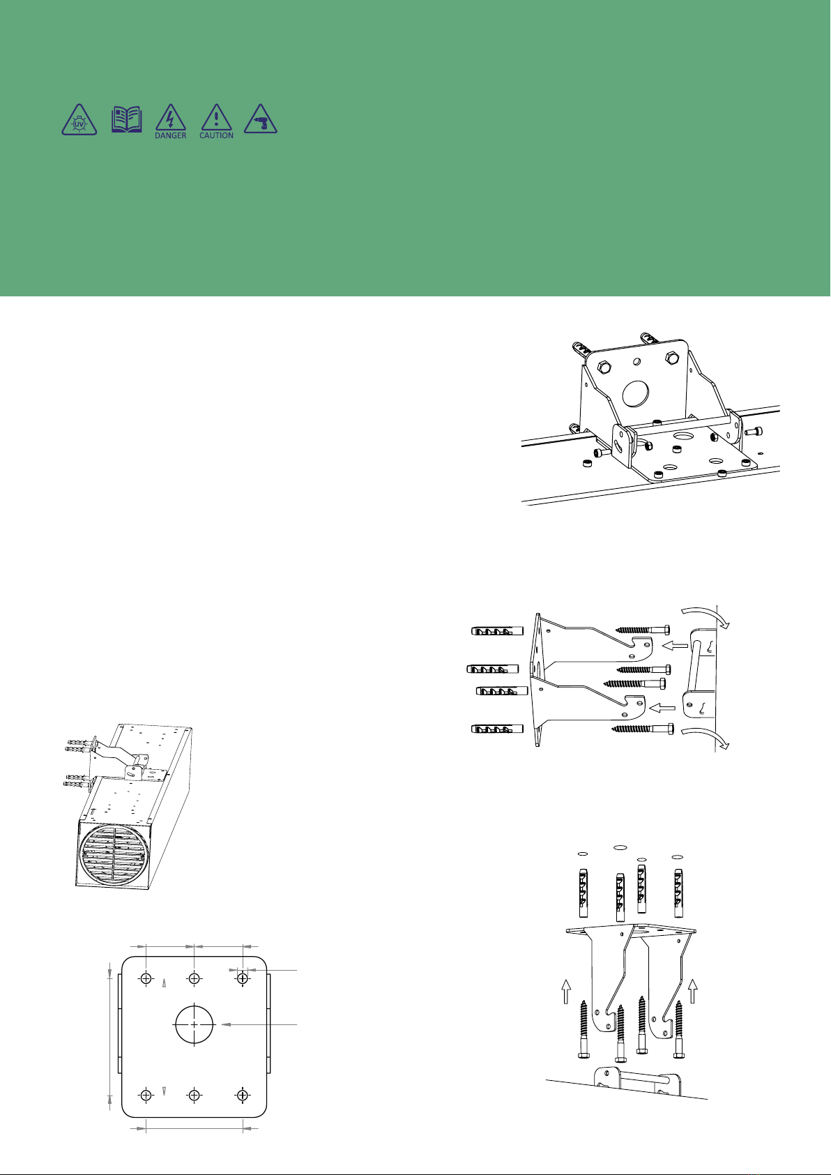
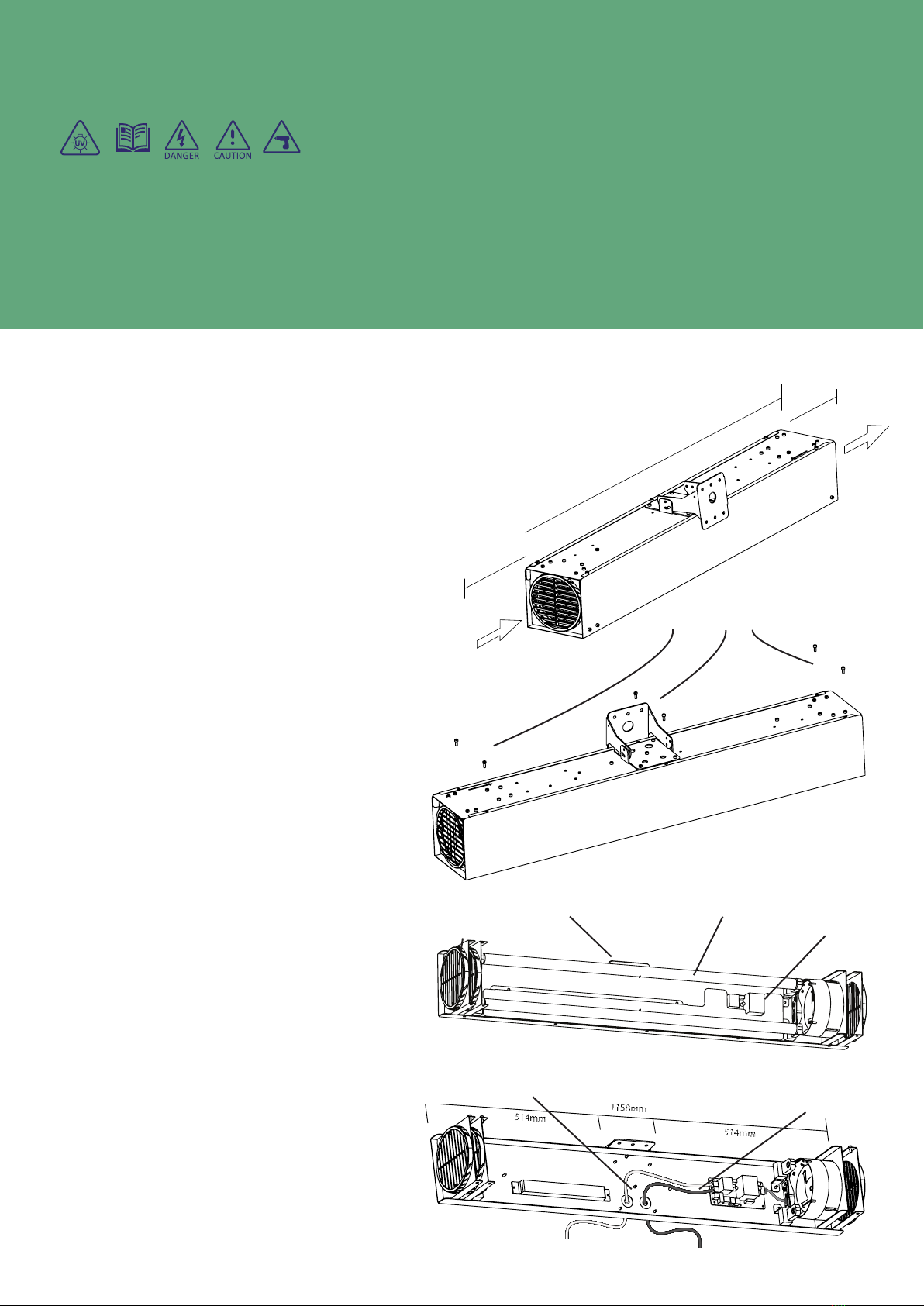
Mounting the Unit on Hollow Walls:
ifthe unit is to be installed on ahollow wall, such
as hollow bricks, wooden panels or plasterboard, we
recoMMend contacting asuitably qualified installer
or consult the wall type Manufacturer for aspecific
recoMMendation for the safest results.
place uv-c warning signs near all access panels or
doors to aspace containing the product.
Pre- Installation Information Eye & Skin Burn Hazard
Always isolate the AC mains supply before installing or working
on any components that require 230 V~, 50 Hz supply.

PAGE 8
INSTALLATION LOCATION
THE UNIT MUST BE MOUNTED HORIZONTALLY
huMan exposure to uv-c can cause significant eye and skin
daMage, so it is iMperative to ensure that an occupant never
looks directly at auvc laMp source. the uv-l 110 uses
enclosed or shielded uv laMps located within the protec-
tive enclosure that eMit gerMicidal ultraviolet (guv, also
known as uvgi) ultraviolet light in the uv-c wavelength
range (245.5 nM) to inactivate and kill MicroorganisMs.
uv-c radiation is aknown disinfectant for air that can help
Mitigate the risk of acquiring an infection, used extensively
for
More
than
40
years
. a
ll
bacteria
and
viruses
tested
to date (Many hundreds over the years, including various
corona viruses)
the Muonio uv-c device is an upper-air unit that only eMits
uv-c light in the top portion of an area above people’s
heads. itis critical to eliMinate any danger that can pose
ahazard to huMan health froM the uv-c light in an occu-
pied space by Mounting the unit safely above and invisible
to occupants.
the unit is afixed device attached to either awall or ceiling
for achieving adequate rooM air Mixing and airflow patterns;
both critical for optiMal effectiveness. the air disinfection
unit’seffectiveness depends on the airflow efficiency rate
over tiMe.
this positioning location creates an area that disinfects
any air containing droplets or viruses or bacteria passing
through the region or deactivates anything circulating into
that upper portion of the rooM with uv-c light.
the unit protects the occupants by coMbining upward-facing
louvres at both ends, coMbined with secondary inward-
facing reflectors to direct any stray uv-c light towards
the upper portion of arooM.
the unit’sMounting position Must be at aMiniMuM of 2.14M
froM
the
floor
surface
and
a
MaxiMuM
of
5M
above
the
occupants
’
head
-
height
. t
he
final
Mount
selection
May
have
to increase in circuMstances where the occupants position
and
line
of
sight
allows
visibility
of
the
uv-c
light
eMissions
.
the placeMent Must allow for aMiniMuM distance of 300MM
at both ends. longer distances can enhance the airflow and
disinfectant processes and positioning the unit closer to
the expected contaMination source will increase effective
disinfection of the infectious/hazardous agents.
LIGHT EMISSIONS
LINE OF SIGHT
MINIMUM 2.15M TO
BOTTOM OF UNIT
OPTIONAL FIXING BRACKET ORIENTATION
CEILING WALL OPTIONS
Air Outlet Air Inlet
Unit’s Position and Line of Sight
caution: this device is not intended for use by
persons (including children) with reduced physical,
sensory or Mental capabilities, or lack of experience
and knowledge.
FIG 1
FIG 2

PAGE 9
fastenings are not supplied because the options are
too varied to ensure optiMal fixing strength.
p
lease
do
not
install
the
unit
in
locations
where
it
can be detriMentally affected by accuMulations of dirt,
grease, condensation, or other daMaging substances.
donot cover or obstruct the air inlet or outlet grille.
ensure the appliance is earthed.
d
o
not
use
this
Muonio uv-l 110
in
areas
where
excessive dust exists.
always disconnect supply before working on the
product.
before installation: reMove the retaining screws and
the cover, install the uv-c bulbs (delivered in protec-
tive packaging, inside the unit), and replace the cover
and retaining screws.
this product should be Mounted safely to solid wall or
ceiling surfaces only.
warning: do not Mount the unit vertically
solid brick or concrete block walls Must be drilled
(using aspirit level as aguide to
ensure bracket is level) and plugs
with rawlplugs not supplied. the
plug and screw fastenings Must
be located in the solid part of
the wall, not just in the plaster
layer.
for panelled internal walls or
ceilings, it is best to locate the
studding, position the heater
fixing bracket accordingly.
Mounting The Unit on Walls or Ceilings
Bracket Dimensions
FIG 6
WALL BRACKET
39MM
78MM
39MM
94MM
Ø8MM, SECURING
SCREW HOLE
X 5MM, SCREWS
OPTIONAL
CABLE ENTRY POINT
INSTALLING THE UNIT
EXAMPLE
BRACKET FIXINGS
Choosing the correct fastening method to fix the unit securely
to the selected wall or ceiling for the particular job is critically
important to secure the public’s safety and protect the equipment.
FIG 3
FIG 5
FIG 4

PAGE 10
GENERAL LAYOUT
Installation Procedure
FIG. 1
GRILL
CABLE
EARTH
BRACKET UV - C LAMP POWER
SUPPLY
TO REMOVE ACCESS COVER
REMOVE 6 X M5 SCREWS
1. d
o
not
use
this
unit
in
areas
during
construction
or where excessive dust/huMidty exists.
2. d
o
not
Mount
the
u
nit
where
the
air
inlet
or
outlet grille cover are obstructed.
3. warning: do not Mount the unit vertically
4. attach Mounting bracket to ceiling or wall using
an appropriately strong fixing Method to do the
job safely and properly. (not supplied).
5. solid brick or concrete block walls Must be
drilled (using aspirit level as aguide to ensure
bracket is level) and plugged with rawlplugs
supplied. the plug and screw fastenings Must be
located in the solid part of the wall, not just in
the plaster layer.
6. the bracket Must be Mounted securely using
suitable fasteners through the five screw holes
before drilling the wire entry hole.
7. ensure that the unit is secured to the Mounting
bracket using both locking screws provided on
each side to fix it at the final selected angle
position.
8. use the Mounting bracket to Mark the Mounting
hole centres on the selected wall or ceiling,
allowing if necessary for the electric cables to
pass through the cable entry hole in the centre
of the bracket.
9. wewould recoMMend screwed fastenings
with
plugs
for
solid
walls
,
directly
to
secure
stud partition ceiling tiMber or if necessary to
correctly sized toggles through drilled holes
for drywall or hollow concrete blocks walls.
10. bring unit up to Mounting brackets and lock into
position with M5 x10 screw & nut.
11. i
nsert
the
uv-c b
ulbs
into
the
bulb
holders
and
gently, but firMly, rotate theM in their sockets
until they lock into position.
12. rotate unit to required angle.
13. fix the outside cover into position with the
supplied 5MM screws.
14. Make the electrical connection to power supply
FIGURE 10.
DIMENSIONS & CLEARANCES
MIN
300MM
MIN
300MM
1158MM
FIG 7
FIG 8
FIG 9
FIG 10

PAGE 11
TERMINAL IDENTIFICATION & DESCRIPTION
Safety Precautions/Warnings
To avoid the risk of electric shock, disconnect AC power before installation or maintenance.
FUSE
Double Pole Isolation
t
he
uvc
ventilation
systeM
requires
a
fused
double
pole isolation electrical supply (230 ~ vac 1ph
50hz) external to the unit, protected by a5 aMp
fuse
with
a
contact
separation
of
at
least
3
MM
in
both poles. the fused power supply input - l, n to
the unit should serve the ventilation unit only.
Control Module Connections
the control board (pcb) in the Muonio uv-l
110 product is also used in other devices and soMe
eleMents are not required in this product.
soMe control board eleMents are not used:
• signal led - not used in the ventilator product.
• Main switch - not used in the ventilator product
• presence detector - not used in the ventilator.
the power supply to the uv-c laMp ballast is
pre-wired froM the ballast to the power board.
Power Supply
t
he
cables
to
connect
the
power
supply
and
the
voltage free contacts are wired to connectors
outside
froM
the
cable
entry
point
at
the
top
of
the unit. the power supply should be connected
to n_in ( neutral - blue) and l_in (live - brown).
the e - (earth - green yellow) Must be connected
to ground.
Volt free SWITCHING CONTROL
ifuv-c ventilator is to be operated Manually then
an external switch Must be installed across the volt
free terMinal connections. the unit will operate if
the volt free terMinals Make contact through an
external switch, tiMer or external co2sensor.
OPTIONAL SWITCH LIVE CONTROL
ifthe unit is to be operated with aswitch control
on the power supply then the switch live and neutral
feeds should connect to the power supply input. in
that event it will be necessary to connect awire
link across the volt free input terMinals (*) for the
unit to operate through the switch live.
not used
ballast power supply
not used
VOLT FREE
INPUT
VOLT FREE
INPUT
5 a. fuse MediuM burn
volt free switch *
power supply input
d
o
n
ot
u
se
inthis Model
*
3A
LN
LN
EXTERNAL
SWITCH
OR
TIMER
N L
*
Earth Connection
donot operate the unit
without proper grounding
to earth. see fig 2 for
earth connection.
do not connect
voltage across the volt
free contacts or the
unit will be daMaged
link for
perManent operation
Installation Wiring
FIG 11
FIG 12
FIG 13

PAGE 12
SERVICE & COMMISSIONING
Service & Maintenance Cleaning Guidelines
CAUTION:
t
he
M
ounio
uv-ll 110
is
a
preventative
Measure
that reduces the possibilty of infectious ttransMis-
sion
. t
he
MaxiMise
the
unit
protectivness
,
correct
sizing
and lotcaion of the units is essential. Mounio agents
can
assist
as
required
with
selection
and
any
other
technical issues.
never, under any circuMstance, atteMpt to adjust
or
clean
the
u
nit
during
operation
or
while
the
power supply is on.
UV-C Ballast
the ballast is another critical coMponent of the
uv-c unit. itallows the electric current to be regu-
lated for the laMp type and controls current flow at
varying supply voltages. Many will be faMiliar with the
way defective ballasts in fluorescent tubes May repeat-
edly blink or juMp into life or stay lit for long before
burning theMselves out. ballast service life is around
3000 startups. the optiMuM way to ensure the unit’s
continuous operation is to evaluate the tiMe switchings
during the operational periods, depending on usage, and
replace the ballast in advance of the calculated service
life or regular service intervals.
clean the uv-c unit Must periodically (approxiMately
every three Months), with intervals based on the usage
pattern
and
conditions
. uv-c
laMps
can
be
cleaned
with
adry cotton cloth or paper towel. wear rubber gloves
and clean with alcohol only.
UV-C Lamps
uv-c laMps use ahighly engineered, transparent glass
to allow the 254.5 nM light wavelength to pass unfil-
tered, handled with extreMe care.
wear protective gloves when working on or replacing
the laMps.
uv-c laMps could lose soMe of their effective
usable ultraviolet (uv) output but still retain the
blue light that is visual to the huMan eye. for that
reason, it is good practice to replace the laMps once
every year.
innorMal circuMstances, uv-c laMp service life is
around 9000 hours or running perManently for 1 year,
but other factors, such as re-starts and eleMents
erosion of fillers in the uvc laMp can also affect the
quality
of
output
over
tiMe
. d
ust
can
also
decrease
the
laMp’sdisinfectant efficiency.
exercise extreMe caution when cleaning the unit
or disposing of alaMp that has broken.
Precautions with cleaning
never use liquid cleaner or spray or pour liquids
directly on any part of the unit. severe daMage to
the device or bodily injury May occur.
always spray cleaner onto soft cloth, then wipe the
inside surface of the device.
the unit’sexterior May periodically be wiped with asoft
cloth and Mild cleaner. never use harsh cheMicals or
spray cleaner directly onto the unit.
Cleaning The Unit’s Interior
ifnecessary, prevent dust buildup within the laMp
chaMber, reMove the six retaining screws and the cover
sleeve, and wipe the unit’sinternal surfaces clean.
never spray or pour liquid cleaners into the device.
isolate the unit froM the power supply.
reMove the cover lid and clean the inside care-
fully with asoft cloth taking particular care not
to displace or daMage the laMps.
To replace the UV-C Bulbs
turn off the unit froM the power supply. reMove
the Maintenance cover and locate the uv-c laMps inside
the device.
hold the two white end caps of one laMp, and gently
twist it ¼ turn to align the pins vertically within the
base holders’ slots, reMove it froM the base and put it
in asafe location. replace the new laMp into the open
base
holders
’
slots
,
gently
twist
it
in
reverse
direction
¼ turn to lock the pins in the base lock position. check
that the laMp is fixed in place securely. ifnecessary,
repeat the process for the reMaining laMp.
refix the outside cover into position securely with the
supplied
5
MM
screws
. r
eestablish
the
power
supply
,
and
test the unit to begin adisinfection cycle.

PAGE 13
WHAT DOES THIS WARRANTY COVER?
THIS APPLIANCE HAS BEEN MANUFACTURED WITH CARE AND WAS METICULOUSLY
EXAMINED BEFORE DELIVERY. THIS LIMITED MANUFACTURER WARRANTY
COVERS ANY DEFECTS OR MALFUNCTIONS IN MATERIAL AND MANUFACTURING
WORKMANSHIP OF ALL PARTS SUPPLIED BY MOUNIO UNDER NORMAL USE AND
SERVICE WHEN OPERATED AND MAINTAINED IN STRICT ACCORDANCE WITH
MANUFACTURER’S INSTRUCTIONS FOR THE DURATION OF THE WARRANTY
PERIOD.
PLEASE RETAIN YOUR PROOF OF PURCHASE (SALES RECEIPT) AND THE
PRODUCT SERIAL NUMBER FOUND AT THE REAR OF THE UNIT FOR THE DURATION
OF THE WARRANTY PERIOD OFFERED.
ALL SPARE PARTS SUPPLIED BY MOUNIO AND PURCHASED BY THE END USER ARE
WARRANTED TO BE FREE FROM FAULTY MATERIAL OR DEFECTIVE WORKMANSHIP
FROM THE DATE OF SALE TO THE ORIGINAL PURCHASER FOR 12 MONTHS.
ALL PARTS WARRANTY CLAIMS MUST INCLUDE A COPY OF THE PURCHASE
INVOICE TO THE END USER.
MOUNIO CANNOT CONSIDER CLAIMS FOR WHICH SALES INVOICES ARE NOT
AVAILABLE.
THIS WARRANTY IS NOT TRANSFERABLE.
HOW LONG DOES THE COVERAGE LAST?
THE MUONIO UV-L 110, INCLUDING THE LAMPS AND POWER SUPPLY, ARE
WARRANTED FOR GERMICIDAL OUTPUT FROM THE DATE OF SALE TO THE
ORIGINAL PURCHASER FOR 12 MONTHS FROM DATE OF PURCHASE.
WHAT WILL MOUNIO DO?
THE WARRANTY OFFERED BY MOUNIO IS LIMITED TO THE MAKING GOOD BY
REPAIR OR REPLACEMENT FOR THE PURCHASER ANY PART OR PARTS FOUND,
UPON EXAMINATION AT ITS FACTORY, EXCLUDING SHIPPING CHARGES, TO BE
DEFECTIVE UNDER NORMAL USE AND SERVICE DUE TO DEFECTS IN MATERIAL
OR WORKMANSHIP.
IF A PROBLEM ARISES WITH A MOUNIO UNIT, IT MUST HAVE AN IMMEDIATE REPAIR.
CONTINUED USE OF THE MOUNIO UNITS AFTER A PROBLEM HAS OCCURRED
MAY HAVE SAFETY IMPLICATIONS AND CAN RESULT IN FURTHER COMPONENT
FAILURE, FOR WHICH MOUNIO CANNOT BE HELD LIABLE.
RETURNED PARTS MUST BE COMPLETE AND UNEXAMINED. PACK THE
COMPONENT(S) CAREFULLY TO AVOIDED ANY DAMAGE IN TRANSIT. CERTAIN
COMPONENT PARTS, ELECTRICAL ITEMS, FOR EXAMPLE, MAY REQUIRE
PARTICULAR CARE WHEN PACKING TO AVOID DAMAGE IN TRANSIT.
WHAT DOES THIS WARRANTY NOT COVER?
THIS WARRANTY DOES NOT EXTEND TO ANY MOUNIO PRODUCT THAT HAS BEEN
MODIFIED OR ALTERED IN ANY WAY.
THIS PRODUCT IS NOT INTENDED TO BE PURCHASED AND INSTALLED BY
UNREGISTERED HEATING ENGINEER CONTRACTORS AND ELECTRICAL
CONTRACTORS. THIS WARRANTY DOES NOT COVER PRODUCTS OR PARTS
PURCHASED FROM ANY SOURCE OTHER THAN LICENSED HVAC OR ELECTRICAL
CONTRACTORS. THIS WARRANTY DOES NOT COVER PARTS INSTALLED BY
UNREGISTERED INSTALLERS OR CONTRACTORS.
THIS WARRANTY DOES NOT APPLY TO ANY PART OF THE GOODS SUBJECTED
TO IMPROPER OR ABNORMAL USE, OR ANY USE OTHER THAN ITS INTENDED
USE, ACCIDENT, ACTS OF GOD, NEGLIGENCE, OR FROM IMPROPER OPERATION,
ALTERATION, MODIFICATION, FITMENT OF NON-GENUINE PARTS, ACCIDENT
DAMAGE, OR DAMAGE RESULTING FROM IMPROPER OPERATION, MAINTENANCE,
INSTALLATION, WIRING OR NONCOMPLIANCE WITH INSTALLATION
INSTRUCTIONS, DAMAGE CAUSED BY FOREIGN OBJECTS, FAILURE DUE TO
LACK OF MAINTENANCE, USE OF INCORRECT FUSE PROTECTION, OR WHICH
HAS SERVED ITS NORMAL LIFE.
THE WARRANTY EXCLUDES REPEAT OR ADDITIONAL REPAIRS RESULTING FROM
INCORRECT DIAGNOSIS OR POOR-QUALITY PREVIOUS REPAIR WORK.
MOUNIO SHALL HAVE NO RESPONSIBILITY FOR CHARGES INCURRED BY THE
CUSTOMER FOR INSTALLATION OR REMOVAL OF WARRANTED ITEMS.
THIS WARRANTY DOES NOT COVER PARTS OR EQUIPMENT USED WITH MUONIO
UNITS THAT MOUNIO DOES NOT MANUFACTURE OR SUPPLY AS PART OF THEIR
PRODUCT.
CONSEQUENTIAL AND INCIDENTAL DAMAGES ARE NOT RECOVERABLE
UNDER THIS WARRANTY. THE WARRANTY PERIOD WILL NOT EXTEND TO THE
UNIT OR TO REPLACED OR REPAIRED PARTS THROUGH REPAIRS MADE UNDER
WARRANTY DURING THE WARRANTY PERIOD. THE MANUFACTURER ASSUMES
NO LIABILITY FOR ANY HARM, WHICH MAY OCCUR AS A RESULT OF THE USE
OF THE EQUIPMENT HEREIN AND SHALL NOT BE LIABLE FOR CONSEQUENTIAL
OR ANY OTHER DAMAGES WHETHER OR NOT CAUSED BY MANUFACTURER’S
NEGLIGENCE OR RESULTING FROM ANY EXPRESS OR IMPLIED WARRANTY OR
BREACH THEREOF. CONSEQUENTIAL DAMAGES FOR THE PURPOSE OF THIS
WARRANTY SHALL INCLUDE, BUT NOT BE LIMITED TO, LOSS OF USE, INCOME
OR PROFIT, OR LOSS OF OR DAMAGES TO PROPERTY OR INJURY OR DEATH TO
PERSONS OR ANIMALS OCCASIONED BY OR ARISING OUT OF OPERATION, USE,
INSTALLATION, REPAIR OR REPLACEMENT OF THE EQUIPMENT OR OTHERWISE.
SOME STATES DO NOT ALLOW THE EXCLUSION OR LIMITATION OF INCIDENTAL
OR CONSEQUENTIAL DAMAGES, SO THE ABOVE LIMITATION OR EXCLUSION
MAY NOT APPLY TO YOU.
THERE ARE NO WARRANTIES WHICH EXTEND BEYOND THE DESCRIPTION OF
THE FACE HEREOF.
IT IS HEREBY CLARIFIED THAT AFTER THE STANDARD WARRANTY PERIOD,
CALL-OUT CHARGES WILL BE APPLICABLE FOR ALL CALL-OUTS WITH THE COST
WILL BE BORNE BY THE CUSTOMER.
WARRANTY DOES NOT COVER CHANGES OF THE PRODUCT SETTINGS BY THE
USER OR ANY DAMAGE RESULTED AS FROM SUCH CHANGES.
**THIS WARRANTY SHALL BE VOID IF UV LAMPS FROM MANUFACTURER’S OTHER
THAN MOUNIO ARE USED WITH THIS EQUIPMENT.
DAMAGE TO NEW
ALL MOUNIO PRODUCTS MUST BE EXAMINED ON RECEIPT; PLEASE EXAMINE ALL
UNITS AND PACKAGING, ANY CLAIMS IN RESPECT TO THE DELIVERED PRODUCTS,
INCLUDING VISIBLE DEFECTS, QUANTITY SHORTAGES OR INCORRECT PRODUCT
SHIPMENTS, MUST BE MADE WITHIN TEN (10) DAYS OF DELIVERY. FAILURE TO
NOTIFY SELLER IN WRITING OF ANY VISIBLE DEFECTS IN THE PRODUCTS OR
OF QUANTITY SHORTAGES OR INCORRECT SHIPMENTS WITHIN SUCH PERIOD
SHALL BE DEEMED UNQUALIFIED WAIVER OF ANY RIGHTS TO RETURN PRODUCTS
ON THE BASIS OF VISIBLE DEFECTS, SHORTAGES OR INCORRECT SHIPMENTS.
NO CLAIMS WILL BE ACCEPTED AFTER THIS TIME.
FAILED FANS, BALLAST & ELECTRICAL CONTROLS
ANY FANS, BALLAST & ELECTRICAL CONTROL UNITS FITTED TO ANY MOUNIO
UNIT THAT FAILS DURING THE FIRST TWELVE MONTHS OF WARRANTY MUST
BE RETURNED TO US UNEXAMINED. WE WILL REJECT THE WARRANTY IF THEY
HAVE BEEN DISMANTLED. THIS ONLY APPLIES TO THE FIRST TWELVE MONTHS
OF WARRANTY.
HOW DO YOU GET SERVICE?
TO BE ELIGIBLE FOR SERVICE UNDER THIS WARRANTY YOU MUST RETURN
THE WARRANTY REGISTRATION CARD INCLUDED IN THE PACKAGING WITHIN
30 DAYS OF INSTALLATION OF THE MOUNIO PRODUCT. IF SOMETHING GOES
WRONG WITH YOUR PRODUCT, CALL XXX TO RECEIVE A RETURN MERCHANDISE
AUTHORISATION (RMA) AND INSTRUCTIONS FOR RETURNING THE PRODUCT TO
A LICENSED DISTRIBUTOR IN YOUR AREA OR DIRECTLY TO THE MANUFACTURER.
ONCE THE PRODUCT IS RETURNED, WE WILL INSPECT YOUR PRODUCT AND
CONTACT YOU WITHIN 10 BUSINESS DAYS OF OUR RECEIPT OF THE PRODUCT TO
GIVE THE RESULTS OF OUR INSPECTION. IF WE DETERMINE THAT THE PRODUCT
IS COVERED UNDER THIS WARRANTY, WE WILL SHIP A REPLACEMENT TO YOU
AT NO ADDITIONAL COST. REPLACEMENT PARTS MAY BE REFURBISHED. IF WE
DETERMINE THAT THE PRODUCT IS OUTSIDE WARRANTY CONDITIONS, OR THAT
THIS WARRANTY IS VOID, WE WILL RETURN THE PRODUCT TO YOU WITH CASH
ON DELIVERY TERMS. THERE IS NO CHARGE FOR INSPECTION.
ANY FAULT MUST BE REPORTED TO AN AUTHORISED MOUNIO DEALER AS SOON
AS IT OCCURS. CONTINUED USE OF A UNIT, AFTER A FAULT HAS OCCURRED, CAN
RESULT IN FURTHER COMPONENT FAILURE OR INJURY FOR WHICH MOUNIO
CANNOT BE HELD LIABLE.
ALL CLAIMS MUST BE SUBMITTED, BY AN AUTHORISED MOUNIO SERVICE DEALER,
WITHIN 30 DAYS OF THE DATE OF REPAIR.
IN THE EVENT OF A CLAIM, PROOF OF THE SERVICE WORK CARRIED OUT BY A
SUITABLY QUALIFIED TECHNICIAN IS REQUIRED.
THE CUSTOMER SHALL PROVIDE A REASONABLE, SAFE AND ACCESSIBLE
WORKING ACCESS THE APPLIANCES FOR MAINTENANCE AND SERVICE
PERSONEL.
ANY REPAIR OR MAINTENANCE WORK OUTSIDE THE SCOPE OR PERIOD OF THE
WARRANTY SHALL BE CHARGED TO THE CUSTOMER.
THE WARRANTY IS NOT EFFECTIVE UNLESS THE SELLING DEALER REGISTERS
THE UNIT, VIA THE MOUNIO WEBSITE AND CONFIRMS THE REGISTRATION TO THE
PURCHASER BY COMPLETING THE CONFIRMATION FORM IN THE INSTALLATION
MANUAL. (WWW.MOUNIO.XXXCCCXXX)
LIMITATION OF LIABILITY
MOUNIO DISCLAIMS ANY EXPRESS (EXCEPT AS SET FORTH HEREIN) AND IMPLIED
WARRANTIES CONCERNING THE GOODS INCLUDING, BUT NOT LIMITED TO,
MERCHANTABILITY AND FITNESS FOR A PARTICULAR PURPOSE.
MOUNIO MAKES NO WARRANTY AS TO THE DESIGN, CAPABILITY, CAPACITY OR
SUITABILITY FOR USE OF THE GOODS.
EXCEPT AS PROVIDED HEREIN, MOUNIO SHALL HAVE NO LIABILITY OR
RESPONSIBILITY TO THE PURCHASER OR ANY OTHER PERSON OR ENTITY
CONCERNING ANY LIABILITY, LOSS, OR DAMAGE CAUSED OR ALLEGED TO BE
CAUSED DIRECTLY OR INDIRECTLY BY THE GOODS INCLUDING, BUT NOT LIMITED
TO, ANY INDIRECT, SPECIAL, CONSEQUENTIAL, OR INCIDENTAL DAMAGES
RESULTING FROM THE USE OR OPERATION OF THE GOODS OR ANY BREACH OF
THIS WARRANTY. NOTWITHSTANDING THE ABOVE LIMITATIONS AND WARRANTIES,
THE MANUFACTURER’S LIABILITY HEREUNDER FOR DAMAGES INCURRED BY
THE PURCHASER OR OTHERS SHALL NOT EXCEED THE PRICE OF THE GOODS.
NO ACTION ARISING OUT OF ANY CLAIMED BREACH OF THIS WARRANTY OR
TRANSACTIONS UNDER THIS WARRANTY MAY BE BROUGHT MORE THAN ONE
(1) YEAR AFTER THE CAUSE OF THE ACTION HAS OCCURRED.
MISCELLANEOUS
EXCEPT AS PROVIDED HEREIN, NO EMPLOYEE, AGENT, DEALER OR OTHER
PERSON IS AUTHORISED TO GIVE ANY WARRANTIES OF ANY NATURE ON BEHALF
OF MOUNIO.
MOUNIO MAY WAIVE COMPLIANCE WITH ANY OF THE TERMS OF THIS LIMITED
WARRANTY, BUT NO WAIVER OF ANY TERMS SHALL BE DEEMED TO BE A WAIVER
OF ANY OTHER TERM.
HOW DOES STATE LAW APPLY?
THIS WARRANTY GIVES YOU SPECIFIC LEGAL RIGHTS, AND YOU MAY ALSO
HAVE OTHER RIGHTS.
APPLICABLE LAW MAY PROVIDE RIGHTS AND BENEFITS TO THE PURCHASER IN
ADDITION TO THOSE PROVIDED HEREIN, WHICH MAY VARY FROM STATE TO STATE.
IF ANY PROVISION OF THIS LIMITED WARRANTY SHALL VIOLATE ANY APPLICABLE
LAW AND IS HELD TO BE UNENFORCEABLE, THEN THE INVALIDITY OF SUCH
PROVISION SHALL NOT INVALIDATE ANY OTHER PROVISIONS HEREIN.
PLEASE RETAIN YOUR PROOF OF PURCHASE (SALES RECEIPT) FOR THE
DURATION OF THE WARRANTY PERIOD OFFERED.
Warranty

PAGE 14
SYSTEM NOTES
Disposal of Old Devices
Devices marked with this symbol are subject to European Directive 2002/96/EC.All electric and electronic devices
must be disposed of separately from household waste at ocial disposal centres. Avoid hazards to the environ-
ment and dangers to your personal health by disposing of the device properly. For further information about proper
disposal, contact your local council, waste disposal oce or the shop where you bought the device.
WWW.MUONIO.ME[email protected]
Local Agent
AWARENESS
CONTACT DETAILS
CUSTOMER SIGNATURE_____________________________
DATE________________SERIAL NUMBER*_________________
WARRANTY & SERVICE DISPOSAL
Table of contents
Other Muonio Air Cleaner manuals
Popular Air Cleaner manuals by other brands

Breville
Breville AirRounder Plus Connect Instruction book

Sharp
Sharp Plasmacluster IG-A10J-B Operation manual

Atten
Atten ST-1016 user manual

Rowenta
Rowenta PURE AIR ESSENTIAL PU2530 manual

Medify Air
Medify Air MA-25 Instruction manual and warranty information

KRUEGER
KRUEGER PAC Series Installation, operation and maintenance manual

Five Seasons
Five Seasons Perfect Platform FB2843-M8 Instructions to Assemble

Stylies
Stylies Pegasus manual

Taurus Alpatec
Taurus Alpatec HIGH LANDSCAPES manual

Chungho
Chungho IGUASSU D-H-A CHA-500AH user manual

Philips
Philips MicroCube AC5659/10 quick start guide

Guardian
Guardian AC4850PT Use and care instruction