Channel Plus H512 User manual

The H512 single channel modulator creates a new channel to add to
existing television channels. The H512 creates this new channel from a
video signal it receives via a single CAT-5 cable connected to one of its
companion products such as the H721 camera or H110 wall plate. Any TV
connected to the output via coax can receive the signal, when tuned to the
proper channel.
2
ChannelPlusmodel H616
TelephoneMaster Hub (4 lines x 6 phones)
TelephoneMaster Hub (4 lines x 6 phones)
TelephonesTelephones
From
Telco
From
Telco
RJ31XRJ31X
Out
Expansion
Ports
Expansion
Ports
R
T
R
T
4
R
T
R
T
3
R
T
R
T
2
R
T
R
T
1
Typical Installation
Programming the H512
DECLARATION OF CONFORMITY
THIS DEVICE COMPLIES WITH PART 15 OF THE FCC RULES. OPERATION IS SUBJECT TO
THE FOLLOWING TWO CONDITIONS: (1) THIS DEVICE MAY NOT CAUSE HARMFUL
INTERFERENCE, AND (2) THIS DEVICE MUST ACCEPT ANY INTERFERENCE RECEIVED,
INCLUDING INTERFERENCE THAT MAY CAUSE UNDESIRED OPERATION.
FCC classifies this product under part 15 of its rules as a “television interface device”.
Systems designed using television interface devices have the following legal requirements:
1) The modulated channel signal strength may not exceed 15.56dBmV at any television.
2) If an antenna is used in the system, the modulated channel signal strength may not exceed -
51dBmV at the antenna input port.
Any system you design must comply with these regulations. As the installer, you are responsible.
The H512 has the necessary characteristics to comply with the above requirements as designed
without additional accessories.
Installation requirements:
For the Installer:
Federal Regulation 47CFR15.115(b)(1)(i).
Federal Regulation 47CFR15.115(c)(4).
ChannelPlus model H511HHR
Channel Injector (single channel via CAT-5)
ChannelInjector
CAT-5 video
Output
CATV
program
Output
Program
Video Audio L
W3W2
W1
W4
Audio R Power
H512
Enter the new channel using
the push button.Program
Power the H512 last, make all
cable and CAT-5 connections
first.
Program the new channel using the push button to enter channel digits into the
H512. This new channel should be an unused channel. It should have no interference or
trace of a picture - just “snow”. There must also be one unused channel both above and
below the selected channel to avoid interference. Below is a simple step by step example
of how to program a channel - cable channel :
Program
120
Cable HRC and IRC considerations:
Most cable services use standard or IRC frequency assignments. This is the default for the
H512. However, if the cable services use HRC or the TV appears to search for the “created
channel”, program the channel injector for HRC.
Entries 98 and 99 are for setting HRC or IRC only. They do not change the channel number.
For HRC enter a 98. Reset to IRC by entering 99.
CAT-5 Cable Length Limitations:
The length of the CAT-5 cable that runs between the H512 and the camera or wall plate is limited.
See the individual camera or wall plate manuals for these CAT-5 cable run limitations.
Press button
time
program
1
Press button
more times
program
2
Press button
more times
program
10
Wait for LED
(ready for next number.)
power
(press 10 to
enter a ‘zero’)
Wait for LED
(ready for next number.)
power
LED comes back on when
done. If an incorrect
channel is entered, LED
will flash quickly and
return to the previous
setting.
3
1) Hook from the top
2) Swing into place
3) Push button to lock
Single Channel Modulator
1
CAT-5 video
ChannelPlus Single Channel Modulator
OpenHouse modules attach from the top
tm
Televisions
+12vdc
Gnd
IR
Modulators CATV
/Ant
A
B
+Pwr
High Headroom Amp w/IR Engine
UP TO 8 TELEVISIONS
Coax Panel (Model H838HHR typical)
350-079 Power Supply (Included).
To camera or Wallplate
(H721 typical)
Terminate cable with a
RJ-45 connector and
connect to the H512.
Use T568A Residential wiring pin out.
Specifications: typical @ 25 C ± 5 C
OO
Default Setting for H512
When not using baseband connectors insert all jumpers, (W1, W2, W3 &
W4 are installed at factory).
Optional Settings
To use baseband connectors as outputs when H512 receives video from
Cat-5 video source, Insert W2, W3, & W4, Remove W1.
To use baseband connectors as inputs when using the H512 as a stand
alone modulator. Insert W1 and remove W2, W3 & W4.
Jumpers
600mA
350-079
RF output
Power supply
performance
Video
Inputs
(Ports)
65-125(excluding 95-99)
14-64
channel ranges
model number
signal/noise 55 dB
-60 dBC
+25 dBmV (+85dBuV)
105-125 VAC
-45dBC @ 12MHz
15 VDC
differential phase <4º
differential gain
L & R inputs combined for monaural
4%
audio 1 V rms @ 47k
video
UHF CATVstandard
1Vp-p@75
output level
input power
IM distortion
alternate channel
output voltage
output current
>1M in loop through mode (LOOP)
75 in normal mode (NORM)
video termination
(switch selectable)
Things To Watch For:
Herringbone interference on modulator channel (diagonal lines):
Herringbone interference on many channels, including modulated channel (disappears
when you remove the CATV/antenna feed)
You may have chosen a
channel number that is not completely vacant. Distant UHF stations may not be watchable, but
will cause interference if you try to create a new channel at the same frequency. Also, cable
companies often have extra signals where there should be none. Try moving the modulator
channel to another number. You may have to add a low pass filter to remove the cable company
noise. If the filter does not work, try adding a DC-block to remove common mode interference.
: The RF amplifier can be overloaded by abnormally
strong signals. Often, you can cure the problem with a simple attenuator. Use a variable
attenuator and try to find a signal level where the interference just disappears. Sometimes, the
problem is one station is far stronger than the rest. In this case, attenuating all of the signals with
a simple attenuator may cause the desired stations to be weak (snowy). You must reduce the
strength of the only offending station. A common FM trap will help if the problem is a nearby FM
tower. If the problem is a nearby TV station, often the station management can provide suitable
filters.
No picture
Weak ChannelPlus UHF channel
Audio volume is low
No color on ChannelPlus channels
… Check that the TV and the modulator are tuned to the same channel. For example,
if the modulator is broadcasting on UHF channel 16, make sure the TV is on UHF 16 rather than
CATV 16. UHF 16 and CATV 16 are at different frequencies. Also ... Make sure the H512 and
camera or wall plate are wired properly.
… If the TV has a separate UHF input, be sure that it is
connected.
… The left and right audio inputs are combined for monaural. For proper
audio level, both right and left inputs must be used. If you have a mono source, connect it to both
right and left inputs using an RCA ‘Y’ connector.
… You may have chosen the incorrect cable standard. Not
all televisions can accommodate the 1.25MHz frequency difference between the H and I cable
standards. See the section on programming.
All manuals and user guides at all-guides.com
all-guides.com

multiplex
technology, inc.
®
***
3001 Enterprise Street, Brea, CA 92821-6213, U.S.A.
714-996-4100 800-999-5225 FAX 714-996-4900 www.openhousesystems.com
TM
ChannelPlus®
Single Channel Modulator
Model H512
ChannelPlus Enclosures, Modules,
Accessories & Wall Plates
ChannelPlus model H628
Data Hub (8 cables, TIA-568A) Category 5 Compliant
OUT
IN
532-230 5MHzto 1000MHz
OUT
IN
OUT
IN
OUT
IN
OUT
IN
SPLITTER
COMBINERCOMBINER
R
TelephonesFrom
Telco
ChannelPlus model H801
Combo Hub (2 lines x 6 phones, 1input x 4 televisions)
R
T
2
R
T
1
ChannelPlus model H616
Telephone Master Hub (4 linesx6phones)
Telephones
From
Telco
RJ31X
Out
Expansion
Ports
R
T
4
R
T
3
R
T
2
R
T
1
Starter systems
RF splitters and telephone punch
downs. When it is time to upgrade,
just snap this module out and
replace with one of more of the
more sophisticated units.
Data hubs
Termination blocks for the CAT-5 cables,
Ethernet hubs. Bring the Internet to any
room in the home. Or create a home data
network.
Telephone hubs
Connections for 1-4 phone lines to
every room. Starter hub adds RJ-
31X jack for security system dialer.
Coax panels
Distribute antenna or cable TV to every
room of the house. Some models include
bi-directional amplifiers for interactive cable
systems. Some models include
IR engines.
modulator
inputs and
AV modulators
(for service center)
Create a new TV channel for a front
door camera. Some models feature
Cat-5 input connections.
Warranty
Multiplex Technology, Inc. warrants this product to be free from defects in materials and workmanship
for a period of one year from the date of purchase or MTI will repair, or at its option, replace the
defective product. To obtain warranty service, call MTI for a return material authorization (RMA)
number and return the product prepaid to Multiplex Technology, Inc., 3001 Enterprise Street, Brea, CA
92821, Attention: Customer Service. Please put the RMA number on the outside of the carton.
Any implied warranty arising from the sale of the product including implied warranties of
merchantability and fitness for purpose are limited to the warranty stated above. MTI shall not be
responsible for losses or damages or expenses, whether direct, consequential or incidental arising
from the use of or the inability to use this product. Some states do not allow limitations on how long the
implied warranty lasts or the exclusion or limitation or incidental or consequential damages, so the
above limitations and exclusions may not apply to you. This warranty gives you specific legal rights,
and you may have other rights which may vary from state to state.
TM
Service center
enclosures
A full line of OpenHouse compatible
enclosures, from simple, inexpensive
mounting plates to high capacity in-wall
cabinets. AC outlets can be mounted
inside the cabinets using a UL listed
accessory.
AV modulators
(for media center)
Create new TV channels for DVD, VCR,
or a satellite receiver. These modulators
sit in the media center. Some offer true
MTS stereo.
®
model 5445 quad digital modulator
pll frequency control
D
C
BA
program
select
Wall plates
Wall plate systems for all rooms. The typical room gets TV
and telephone. The Home office wall plate adds data ports.
The media center wall plate adds satellite feeds.
IR Accessories
Control video devices from any room.
Wiring a house for OpenHouse
Typical Room Media Center Home Office
Good
Better
Best
1 Cat-5
1 RG-6
1 Cat-5
3 RG-6
1 Cat-5
2 RG-6
2 Cat-5
1 RG-6
2 Cat-5
2 RG-6
2 Cat-5
3 RG-6
3 Cat-5
3 RG-6
2 Cat-5
2 RG-6
3 Cat-5
3 RG-6
Good ...
Typical room - phone, TV
Media center - phone, satellite receiver, AV modulators
Home office - phone, TV,
Better …
Typical room - phone, TV, ethernet
Media center - phone, TV, satellite receiver, AV modulators
Home office -
Best …
cable modem
ethernet,
phone, TV, ethernet, cable modem
Typical room - phone, TV, ethernet, satellite receiver
Media center - phone, TV, ethernet, satellite receiver, AV modulators, hi-speed data
Home office - phone, TV, ethernet, satellite receiver, cable modem, hi-speed data
The cables in an OpenHouse run from the various rooms of the house
directly to the service center location.(This is known as ‘home run’
wiring.) Two types of wire are used for communication and
entertainment: Cat-5, 4-UTP (4 nshielded wisted airs) wire handles
data or 1 to 4 telephone lines. RG-6 coax handles television (antenna or
cable), satellite dish, cable modem, or AV modulator signals. (An AV
modulator creates new TV channels for front door camera, DVD player, a
VCR or a satellite receiver.)
We recommend the following pre-wire schemes . Run these wires from
the service center to the rooms indicated.
UTP
Multiplex Technology, Inc., Brea, CA 92821Multiplex Technology, Inc., Brea, CA 92821
600-233 Rev. A600-233 Rev. A
Compatible
New ChannelPlus products are added all the
time. Visit out website to learn more:
www.openshousesystems.com
All manuals and user guides at all-guides.com
Other Channel Plus Modulator manuals
Channel Plus
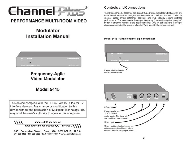
Channel Plus 5415 series User manual

Channel Plus
Channel Plus 5415HD User manual
Channel Plus
Channel Plus 5214 User manual
Channel Plus
Channel Plus 5425 User manual
Channel Plus
Channel Plus 5525 User manual
Channel Plus
Channel Plus CHANNEL PLUS 5314 User manual
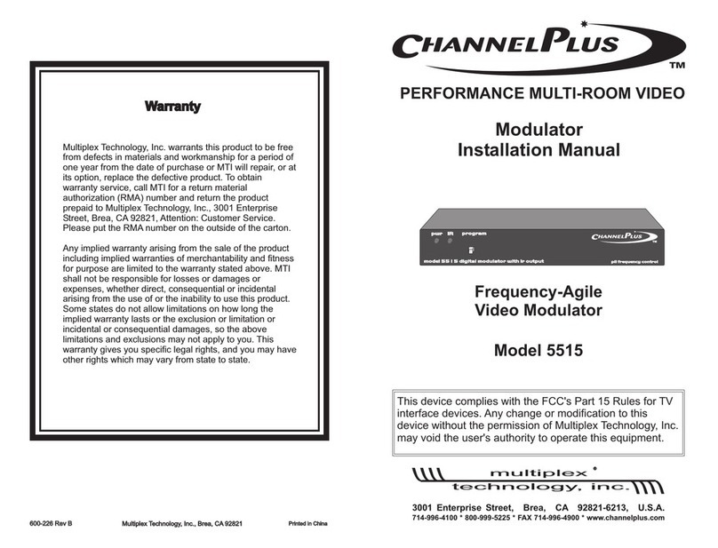
Channel Plus
Channel Plus 5515 User manual
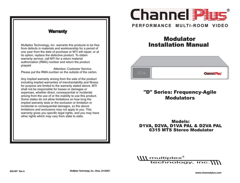
Channel Plus
Channel Plus D1VA User manual

Channel Plus
Channel Plus 5114 User manual
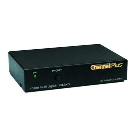
Channel Plus
Channel Plus 5415 User manual
