Chapman Machinery TF Series User manual


Page 2
Contents
HSE Information................................................................................................................................................. 3
Important Safety Information ........................................................................................................................... 4
Safety Information......................................................................................................................................... 4
Transportation Safety.................................................................................................................................... 4
Operating Safety............................................................................................................................................ 4
Description......................................................................................................................................................... 5
Identification.................................................................................................................................................. 5
Implement Decals.......................................................................................................................................... 6
Attachment........................................................................................................................................................ 7
Before Attaching the Machine ...................................................................................................................... 7
Attaching the Machine .................................................................................................................................. 7
Drop Size Adjustment & Calibration.................................................................................................................. 8
Sensor Change / Adjustment............................................................................................................................. 9
Control Box ...................................................................................................................................................... 11
4 Button Model (FROM October 2015)....................................................................................................... 11
Operating Limits & Recommendations ........................................................................................................... 13
Forward Speed............................................................................................................................................. 13
Storage......................................................................................................................................................... 13
Troubleshooting............................................................................................................................................... 14
Warranty.......................................................................................................................................................... 15
The Chapman Warranty .............................................................................................................................. 15
Warranty Conditions ................................................................................................................................... 15
Transfer of Warranty................................................................................................................................... 15
THIS MANUAL MUST BE HANDED TO THE OPERATOR BEFORE USE. THE OPERATOR MUST UNDERSTAND FULLY THE
CONTENT OF THIS HANDBOOK BEFORE USING THE MACHINE FOR THE FIRST TIME. OF THE IMPLEMENT IS
RESOLD, THIS MANUAL MUST ACCOMPANY THE MACHINE.
NOTE:
The information contained in this manual is correct at the time of going to press. However, in the course of
development, changes in specification are inevitable. Should you find the information given differs from your
machine, please contact Chapman Machinery Ltd direct for advice. Use only Chapman Genuine Service Parts on
Chapman Machinery and Machines.

Page 3
HSE Information
Safe use of all-terrain vehicles (ATVs) in agriculture and forestry –AIS Sheet 33
Introduction
This information sheet gives advice on the safe use of ATVs. It covers
the two main types used in off-road working in agriculture and
forestry, which are:
•sit-astride ATV / sit-in machines
•side-by-side mini-utility vehicles,
The Full HSE information sheet can be found here or using the QR
Code at the bottom of the article:
https://www.hse.gov.uk/pubns/ais33.pdf and must be read prior to
any ATV/UTV use. Below are related extracts to trailed machinery.
REMEMBER - GET PROPERLY TRAINED AND ALWAYS WEAR
HEAD PROTECTION
Training
Under the Provision and Use of Work Equipment Regulations 1998
(PUWER), there is a legal requirement for employers to provide
adequate training, and to ensure that only employees who have
received appropriate training in their safe use, including the use of
any towed equipment or attachments, are permitted to ride ATVs.
The same requirements apply to the self- employed. HSE regards
training provided by recognised training providers as being
adequate for the purposes of PUWER.
Protective clothing
More than half of all ATV riders have been thrown off at some time.
As these machines are not fitted with either a cab or roll bar, your
only protection is what you wear.
●
Head protection is vital. The majority of ATV fatalities in the
UK in the last ten years have been caused by head injuries.
Nobody who died from head injuries was wearing a helmet.
Helmets would certainly have prevented most, if not all, the
deaths. Youshould always wear a helmet when riding an
ATV. All helmets should have a chinstrap and be capable of
being used with suitable eye protection. The type of helmet
chosen should be based on an assessment of the
circumstances in which the ATV will be used, eg the types of
surface travelled over and anticipated speeds. The harder the
surface and higher the speed the greater the degree of
protection needed. NB: Forestry helmets and industrial hard
hats are not acceptable for any ATVoperations.
●
Wear clothing that is strong and covers your arms and legs.
Gloves are useful for protection and to keep hands warm in
cold weather for good control of the ATV.Wear sturdy, ankle-
covering footwear, eg boots or wellingtons that are strong,
supportive and have good wet grip.
●
Protect your eyes from insects and branches with either a
visor or goggles.
Trailed equipment and loads
Ensure all riders know the manufacturers recommended
towing capacity and drawbar loading limit. Always operate
within these requirements.
Remember that your ability to control the ATV by your body
movements will be considerably reduced when carrying a load or
towing a trailer.
●
When selecting trailed equipment look for:
-
over-run brakes;
-
a swivel hitch drawbar;
-
bead lock rims on wheels;
-
a low centre of gravity and a wide wheel track;
-
a long drawbar; and
-
attachment points for securing a load.
●
Check the weight ratio between your ATV and its trailed load.
This needs to be assessed for each operation. As a general
guide, on level ground, braked trailed equipment can be a
maximum of four times the unladen weight of the ATV.For
unbraked trailed equipment the maximum should be twice
the unladen weight. These loads should be reduced when
working on slopes, uneven ground or poor surface
conditions. Follow the manufacturers advice for your
particular machine.
●
Weight transfer is also important. Stability and resistance to
jack-knifing is improved if some load is transferred onto the
ATVʼs drawbar. Approximately 10% of the gross weight of the
loaded trailer is recommended, but this should not exceed
the manufacturers drawbar loading limit. Remember that
weight transfer can change dramatically when you start going
up or down hill.
●
When selecting mounted equipment, make sure it is within
the manufacturers approved weight limit, with a low centre
of gravity, and controls which are easy to operate but do not
create a hazard. Where equipment is added to one end of the
machine, add ballast at the other end to maintain stability.
●
Loads carried on racks must be well secured, e.g. with ratchet
straps, and be evenly balanced between the front and rear,
except where they are deliberately altered to aid stability
when going up or down a slope.
●
Only tow a load from the hitch point. Loads towed from other
points such as the rear rack have caused sudden rear
overturning even on slight slopes or with slight acceleration.
Ropes or chains should not be used to drag a load where they
can become caught on a wheel. This may lead to
entanglement with the brake cable, causing unexpected
braking.
Further information
For information about health and safety go to
https://www.hse.gov.uk/
© Crown copyright This publication
may be freely reproduced, except for
advertising, endorsement or
commercial purposes. First published
05/99. Please acknowledge the source
as HSE.

Page 4
Important Safety Information
Always read this manual before fitting or operating the machine –whenever any doubt exists contact your
dealer or the Chapman Machinery Service Department for advice and assistance.
DEFINITIONS
The following definitions apply throughout this manual:
WARNING - An operating procedure, technique etc., which can result in personal injury or loss of life if not
observed carefully.
CAUTION - An operating procedure, technique etc., which can result in damage to either machine or equipment if
not observed carefully.
NOTE - An operating procedure, technique etc, which is considered essential to emphasis.
LEFT & RIGHT HAND - This term is applicable to the machine when attached to the towing vehicle and is viewed
from the rear –this also applies to tractor references.
Safety Information
•Do not operate this equipment unless you have studied this manual in full
•Only use this machine for its designated task - improper use is both highly dangerous and damaging to
machine components
•Both operators & maintenance fitters should be familiar with the machine and fully aware of dangers
surrounding improper use or incorrect repairs
•Before starting, carry out a visual check on both machine & towing vehicle as regards functionality,road
safety & accident prevention rules
•Even when using the machine correctly, accidents can occur. It is imperative that nobody stand withinthe
danger area. If working near roads, buildings or animals, special attention must be taken to ensure safety.
•Never wear loose clothing which could get caught in rotating equipment
•Never carry passengers on the towing vehicle
•Do not stand near the machine when operating
•Damaged or missing safety decals must be replaced immediately
Transportation Safety
•When transporting, especially over rough ground, reduce speed to prevent damage to machine.
•This machine is not road legal in its standard form. DO NOT tow on public highways unless you have
specified the road-legal model, and checked that this and the towing vehicle comply with local highway
regulations in place.
Operating Safety
•Pay special attention when working not to harm livestock if crowding around the machine occurs.
•If anything should become entangled in the mechanism, or blocked in the chute, stop the machine and
disconnect the power before attempting to clear the blockage.

Page 5
Description
The TF Series Trailed Feeders are designed for feeding livestock, through deposition of pre-defined drops of
feed, onto clear ground.
The TF Series operate with an electric motor mechanism, ensuring accurate disposition, and industry leading ground
clearance. The rotor and wiring mechanism are all IP67 rated, to ensure trouble-free usage in even the toughest
winter conditions.
The TF350 has approximately 350kg carrying capacity (feed material dependant), a galvanised metal hopper and
PVC cover. Standard wheels are 22x11x8” flotation, with optional heavy duty 25x13x9” traction or road going tyres
available.
These machines should however only be used to perform tasks for which they were designed - use of the machine
for any other function may be both dangerous to persons, and potentially damaging to components. Use of the
machine beyond the stated usage may invalidate any applicable warranty, as well as being potential in breach of
applicable safety regulations.
Identification
Each machine is fitted with a serial plate (shown below) which details the following:
1. Model
2. Date of Manufacture (DOM)
3. Serial Number
4. Mass
When enquiring regarding spares or additional
equipment, ensure you have this information to hand.

Page 6
Implement Decals
If your implement does not contain all of the decals shown below, please contact Chapman Machinery for
replacement decals before use. Note: All decals must be present and visible. It is imperative that these are replaced
if damaged to prevent potential harm to users.
* Carefully read operators manual
before handling this machine.
Observe instructions and safety rules
when operating.
*Caution - Entanglement Hazard.
Keep hands away from moving
parts
Component Identification

Page 7
Attachment
Before Attaching the Machine
Before attachment, ALWAYS ensure the following:
- All safety guards & decals are in good working order and correctly fitted
- Lubrication points have been lubricated as per scheduled maintenance period
- The tyres are free of damage and inflated to the correct pressure
- Electrical connections are free of dirt and moisture
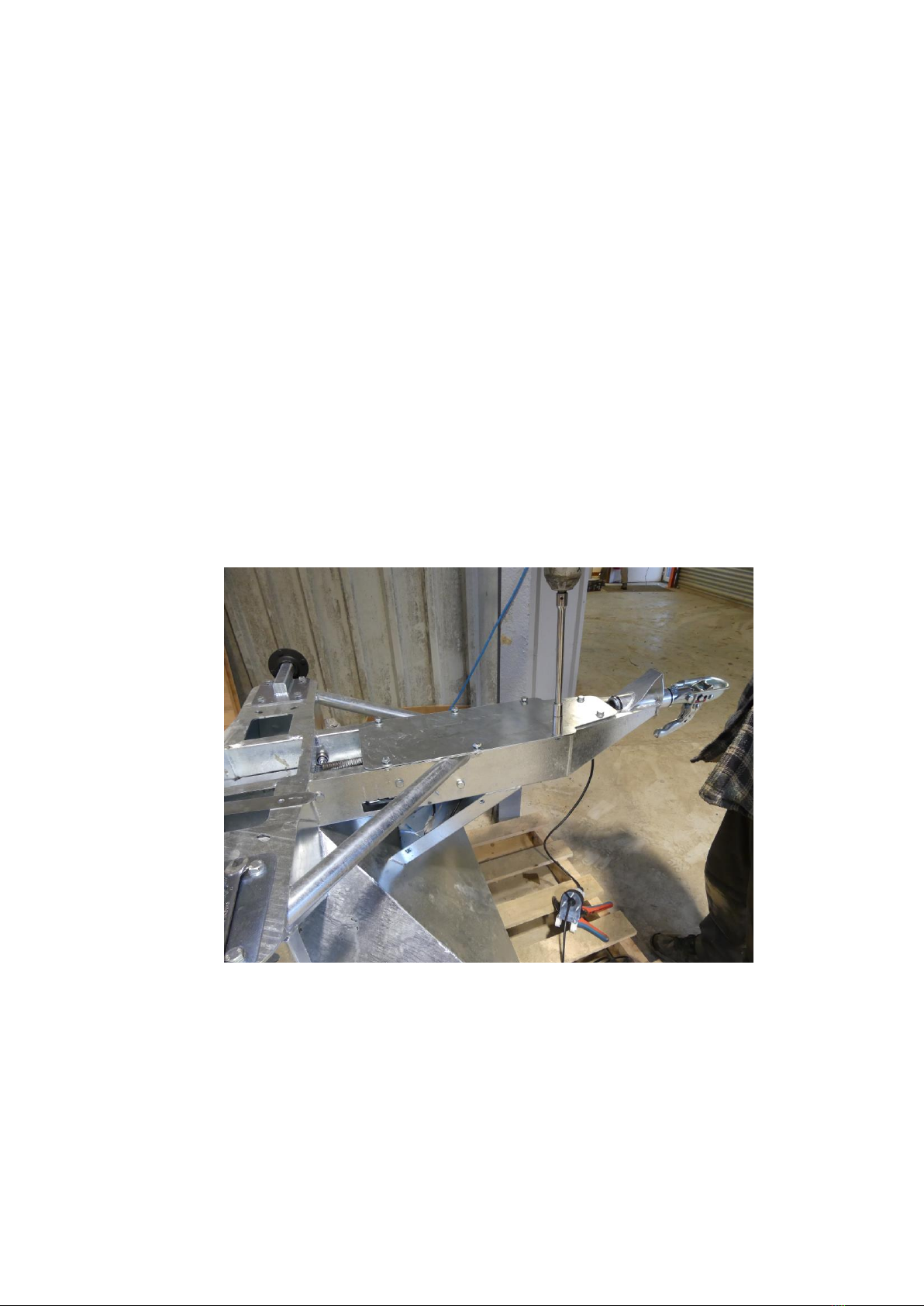
Attaching the Machine
NOTE: This machine is designed to attach to the towing vehicle through a 50mm diameter ball hitch.
1. Reverse the towing vehicle up to the machine.
2. Attach the machine onto the towing vehicle’scoupling.
3. Attach the control cable to the control socket fitted on the towing machine, ensuring a secure connection.
WARNING: ENSURE CONTROL EQUIPMENT IS SECURELY ATTACHED TO THE TOWING VEHICLE BEFORE USE!
4. If required, check and adjust the drop size to suit the material being distributed.
1. Wire Plug
a. Wire Plug supplied with kit –cut approx. 30mm of outer sheath off and shorten BROWN cable by
8mm. Wiring Code:
i. Brown = 7 = Motor –
ii. Red = 3 = Motor +
iii. Green = 5 = Sensor Brown Cable
iv. White = 1 = Sensor White Cable.
b. 2x 40mm lengths of black heat shrink tubing will be required as the plug is designed for a larger cable
diameter than is being used on these machines, so 2 pieces of heat shrink must be heat shrunk onto
the cable at the right point to allow the cable grip to function!

Page 8
Drop Size Adjustment & Calibration
Initially set the Feed adjustment plate to setting 4, as indicated by the arrow on the drop adjustment plate. To
adjust, loosen BOTH hand wheels, and slide the unit forwards or backwards to the desired value. Tighten securely.
Setting 1: Minimum drop size Setting 8: Maximum dropsize
Fill the hopper 50% full of the feed to be distributed. With the machine attached to the towing vehicle and on level
ground, switch the control box on and deposit 10 drops of feed into a bucket. Measure the weight of the deposited
feed and divide by the number of drops (in this case 10) to give the weight per drop.
Adjust the feed adjustment plate as required to increase or decrease the drop size, checking after each adjustment
for the average drop size. Individual drop sizes can vary, especially with large granular materials (eg. cobs) or with
feedstuff containing molasses, so it is important to average the drop size over a number of drops.
It is recommended that the feed be deposited in round numbers, ie. 1kg, 1.5kg, 2kg etc. This allows easy
calculation of required number of drops for different livestock numbers.
The drop setting will differ between feedstuff, due to the different particulate size and any binding agents such as
molasses. It is strongly recommended to re-calibrate if you change feed make-up or consistency.
Once you have set the machine to the desired drop size, securely tighten the two retaining handwheels to
ensure this does not change during use.
Page 9
Sensor Change / Adjustment
If your control box is showing an F1 error and not counting correctly, you may have a problem with the
connectors and/or the sensor may need adjustment.
First, check the plug and socket connection between the control box and the feeder –THIS IS THE MOST
COMMON CAUSE OF PROBLEMS! If required check continuity with a multi-meter.
Plug/socket wiring;
Brown = 7 = Motor –
Red = 3 = Motor +
Green = 5 = Sensor Brown Cable
White = 1 = Sensor White Cable.
If the connectors are functioning correctly then the unit may need adjustment of the sensor and magnet
located within the machine.
Procedure
1. Tilt the drawbar upwards so the machine is resting on the wheels and end of the mudguards, this will
allow easier access. Remove the belly plate using a 17mm socket on the 8 bolts.
2. The sensor can be accessed though the recess in the slide plate shown in the RH corner of the image
below. You should not need to remove the slide plate to access the sensor. If you do need to remove
the slide plate for access, this can be achieved by unclipping the spring from the slide plate and
removing the 5 x bearings and associated bolts which locate the plate. TAKE NOTE OF THE NUMBER
OF WASHERS AS THESE NEED TO BE RE-FITTED IN THE SAME ORDER TO ENSURE THE SLIDE MOVES
SMOOTHLY.
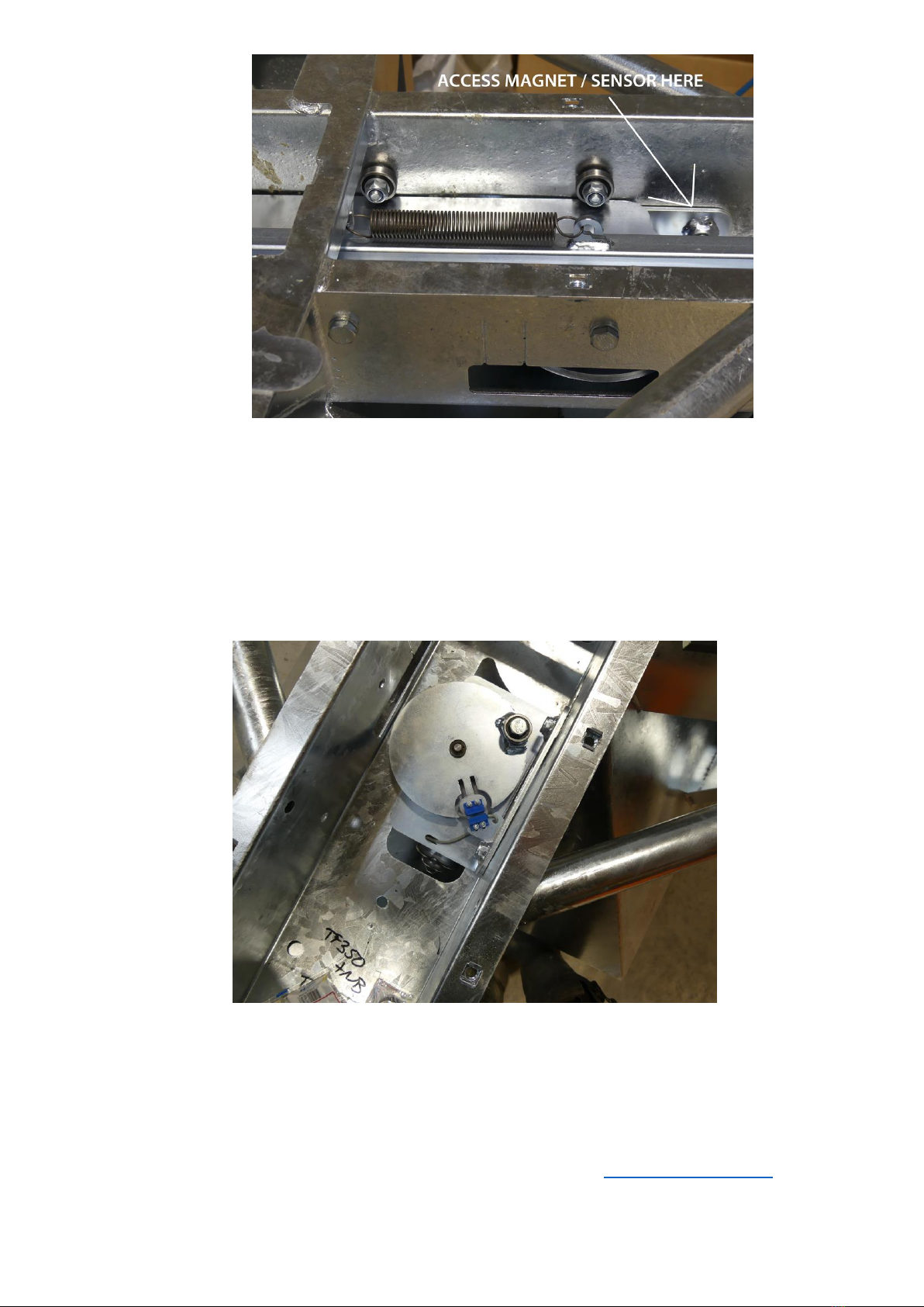
Page 10
3. In the Picture below you can see the sensor (with the wire) and the magnet (fitted to the disc) are
facing each other with approximately 2mm gap between them. The sensors also need to be aligned
vertically (so that they are approximately level with each other).
If required you can bend the sensor support bracket up or down to get vertical alignment, and you
can move the sensor in or out on the slotted holes to get horizontal alignment.
FOR MACHINES USED WITH DUSTY FEED OR FEED WITH ADDITIVES SUCH AS MOLLASES, BUILD UP OF
DIRT CAN AFFECT THE SENSOR OPERATION –IN THIS CASE CLEAN WITH A LOW-PRESSURE WATER
JET.
4. Parts are re-fitted as a reverse of removal, taking care to ensure all bolts are secure and tight. If
adjustments have been made to the sensor, ensure the cable is secured with cable ties or similar to
prevent accidental damage.
Once this has been checked and all dirt removed, your problem should be resolved.
If the problem persists, please contact us 01288 308 149 or email us on sales@chapman.co.uk and we will be
more than happy to help.

Page 11
Control Box
4 Button Model (FROM October 2015)
The 4-button model has two modes of operation;
-
Count Mode: Unit counts up from 0 e.g. 1,2,3,4,5 indefinitely, until the count is paused or theunit
switched off. If the counter reaches 999 then it will reset to 000.
-
Countdown Mode: The desired drop count is set using the up / down arrows in increments of 5. The
unit will then count down and stop at zero.
The unit can be fixed to a suitable surface on the towing vehicle using screws through the fixing lugs
hidden under the two flaps on the left and right of the unit.
Specification
Supply Voltage: 12V DC nominal, 16V MAXIMUM Power
Consumption: OFF: 0.01A
ON: 0.05A
MOTOR RUNNING: 5A *If at all possible wire direct to battery due to current draw*
Operating Temperature: -10°C to +40°C
Fuse: Thermal Reset Polyfuse (Non-serviceable)
Operating life: 100,000 cycles
Protection rating: IP67
Incorrect polarity protection: Yes, diode.
WARNING: This control box features several thermal-rest polyfuse. If this fuse is tripped through a
fault condition, the fuse will reset after approximately 10 seconds when the fuse has cooleddown
sufficiently. In hot ambient conditions this can take significantly longer; likewise, in cold ambient
conditions this will take less time.

Page 12
OPERATION - COUNT MODE
1. Switch the unit on by pressing the ON / OFF button. All segments of the display will lightup.
2. After approx. 3 seconds the display will show 000.
3. Press Run / Pause to start the motor. The unit will count up from 0. Pressing RUN / PAUSE when the unit
is running will stop the motor and pause the counter. Holding RUN / PAUSE for 3 seconds will reset the
counter to 0.
4. Pressing the ON / OFF button at any time switches the unit off.
OPERATION - COUNTDOWN MODE
1. Switch the unit on by pressing the ON / OFF button. All segments of the display will lightup.
2. After approx. 3 seconds the display will show 000.
3. Using the UP / DOWN arrows set the desired drop count.
4. Press the RUN / PAUSE button to start the motor and countdown. The countdown can be paused or
resumed at any time using the RUN / PAUSE button.
5. Once the countdown reaches 000 the unit will stop.
FAULT CODES
OL = Overload. Motor or slide plate jammed, or plug / socket connection is poor. Check plug / socket
connection and check slide plate is not jammed.
F1 = Sensor Fault. No output is being received from sensor. Check plug / socket for dirt or corrosion
preventing contact. Check sensor for damage or corrosion. The unit will continue to operate with this
fault but will not count. To exit this fault condition once the problem has been identified turn the unit
off.
The TF350 electronic system is designed such that a fault can be diagnosed and remedied on site
relatively easily; the motor and rotation sensor are separate components which can be replaced
individually should a fault occur, please contact your distributor or original equipment provider for
assistance and parts should they be required.

Page 13
Operating Limits & Recommendations
Ensure that the operator is suitably qualified to use a machine of this nature and that they have fully read
and
understood this manual - they should be aware of all safety aspects relating to the safe use of the
machine.
It is advisable that all ‘first time’ operators practice using the machine in a clear safe area prior to work in
order to familiarise themselves with its operation.
AFTER APPROXIMATELY ONE HOUR OF WORK WITH A NEW MACHINE, ALL NUTS, BOLTS AND DRIVE
BELTS SHOULD BE CHECKED FOR TIGHTNESS AND ADJUSTED AS NECESSARY!
Operating Limits
WARNING: DO NOT OPERATE BEYOND OPERATING LIMITS, DAMAGE TO MACHINERY OR INJURY TO
OPERATOR MAY OCCUR.
Minimum / Maximum Temperature: -10°C / +40°C
Forward Speed
The forward working speed will affect the distance between drops of feed - to increase the distance
between drops use a faster forward speed, to reduce the distance use a slower forward speed.
Storage
For extended periods of storage, it is advisable that the machine be kept in a clean dry environment
protected from the elements to avoid risk of corrosion.
The machine should be thoroughly cleaned and lubricated prior to storage. At this point it is good
practice to check the machine for worn or damaged components - any parts that require replacing should
be ordered and fitted at the earliest opportunity so the machine is fully prepared for the next seasons
work.

Page 14
Troubleshooting
Problem
Possible Causes
Remedies
Unit will not light up when on
button pressed
Low Supply Power
Charge Battery
IncorrectPolarity/poor
connection
Check connection
Fuse blown (2 button controls
only)
Replace Fuse
Shortage in wiring
Checkwiringloomfordamage
andrepair/replaceasrequired
Motor does not operate even
though control box is on
Poor connection between control
box and TF350
Check plug is clean and moisture
free
Shortage in wiring (may be
indicated by unit losing powerwhen
run button pressed)
Check wiring for damage
Motor Fault
Replace motor, contact distributor
Counter does not operate
Poor connection
Check plug is clean and moisture
free
Fuse blown (2 button controls)
Replace fuse
No signal (Fault F1 on 4-button
model)
Adjust or replace sensor (see page
9 in handbook). The sensor needs
the magnet to pass within 2mm
of it, foreignobject ingress could
have caused fault
Mircoswitch / sensor faulty
Contact distributor
No material is fed
Jammed slide plate
Check for blockages and remove
Hopper bridging
Agitate hopper contents
Drop size varies
Drop adjustment plate loose
Adjust and tighten hand screws
Feed leaking out from chute
Jammed slide plate
Check for blockages and remove
Unitswitched‘off’incorrectly(2
button control units only)
Restart unit, stop slide plate
operation prior to switching control
box off.
Slide plate ‘sticking’ (May be ap-
parent on feeds with high molasses /
binding content
Clean slide plate area. A stronger
return spring can be provided if
required for very sticky feed.
Excessive movement of drawbar
Worn swivel bearings
Replace swivel bearings
Loose bolts
Tighten bolts

Page 15
Warranty
The Chapman Warranty
Chapman Machinery Ltd (herein ‘Chapman’ or ‘Chapman Machinery’) warrants that the machine referred to in the Warranty Registration Form will be free
from manufacturing defects for a period of 24 months from the date of sale. This warranty does not affect your statutory rights, but merely adds to them.
Should you have a problem within 24 months from the date of sale please contact your original dealer, or Chapman Machinery’s Service Department.
Any part found to be defective during this period will be replaced or repaired, at our discretion, by the dealer or a authorised Service Engineer.
Warranty Conditions
1. The Warranty Registration Form must be completed and returned to Chapman Machinery Ltd within 30 days of the date of sale
2. This warranty does not cover defects arising from fair wear and tear, wilful damage, negligence, misuse, abnormal working conditions, use in competition,
failure to follow Chapman Machinery’s instructions (oral or written, including all instructions and recommendation made in the Operator’s Manual) or
alteration or repair of the
machinery without prior approval.
3. The machinery must have been serviced in accordance with the Operator’s Manual and the Service Log must have been
kept up to date and made available tothe
dealer should service, repair or warranty work be undertaken.
4. This warranty does not cover claims in respect of wearing parts such as blades, flails, paintwork, tyres, belts, hydraulic hoses, bearings, bushes, linkage pins,
top links, ball ends unless there is a manufacturing or material defect or the cost of normal servicing items such as oils and lubricants.
5. This warranty does not cover any expenses or losses incurred whilst the machinery is out of use for warranty repairs or parts replacement.
6. This warranty does not extend to parts, materials or equipment not manufactured by Chapman Machinery, for which the Buyer shall only be entitled to the
benefit of any such warranty or guarantee given by themanufacturer to Chapman Machinery. Only genuine replacement parts will be allowable for warranty
claims.
7. All parts replaced by Chapman Machinery under warranty become the property of Chapman Machinery and must be returned to Chapman Machinery if
so requested. Such parts may only be disposed of after a warranty claim has been accepted and processed by Chapman Machinery.
8. Chapman Machinery is not liable under this warranty for any repairs carried out without Chapman Machinery’s written consent or without Chapman
Machinery being afforded a reasonable opportunity toinspect the machinery the subject of the warranty claim. Chapman Machinery’s written consent must,
therefore, be obtained before any repairs are carried out or parts replaced. Use of non- Chapman Machinery parts automatically invalidates the Chapman
Warranty. Failed components must not be dismantled except as specifically authorised by Chapman Machinery and dismantling of any components without
authorisation from Chapman Machinery will invalidate this warranty.
9. All warranty claims must be submitted to Chapman Machinery on Chapman Machinery Warranty Claim Forms within 30 days of completion of warranty
work.
Using the machine implies the knowledge and acceptance of these instructions and the limitations contained in this
Manual.
Transfer of Warranty
The Chapman warranty be transferred to a subsequent owner of the machinery (for use within the UK only) for the balance of the warranty period subject to
all of the stated warranty conditions and provided that the Change of Owner form is completed and sent to Chapman Machinery within 14 days of change of
owner- ship.
Chapman Machinery Ltd retain the right to refuse transfer of warranty.
Chapman Machinery reserves the right to make alterations and improvements to any machinery
without notification and without obligation to do so.

Page 16
EC DECLARATION OF CONFORMITY
Machinery Directive 2006/42/EC
Chapman Machinery Ltd
Hele Barton
Week St. Mary
Holsworthy
Devon
EX22 6XR
The Products Covered by this Declaration
Product: TF350 Trailed Livestock Feeder &Options (Off-Highway)
Standards and Regulations used: Machinery Directive 2006/42/EC
Place of Issue: United Kingdom
Name of Representative: James Chapman
Position of representative: Director
The Basis on which Conformity is being Declared
I declare that as the authorised representative, the above information in relation to the supply /
manufacture of this product, is in conformity with the stated standards and other related documents
following the provisions of Machinery Directive 2006/42/EC directives
The products described above comply with the essential requirements of the directives specified.
Signed:
Date: ......21/01/2014..................
This manual suits for next models
1
Table of contents
Other Chapman Machinery Farm Equipment manuals


Popular Farm Equipment manuals by other brands

DuraTech Industries
DuraTech Industries Haybuster Balebuster 2620 Operating Instructions and Parts Reference

Hyundai
Hyundai WR8020-1050-P-360H1 manual

TKS
TKS FeedBelt Operator's manual

EASY COOPS
EASY COOPS 4x12 Chicken Coop Plan manual

FENDT
FENDT 4300 Workshop service manual

Chapman
Chapman TF350 instructions

Krone
Krone EasyCollect 6000 FP operating instructions

Land Pride
Land Pride RCD1884 Operator's manual

Nutriculture
Nutriculture Amazon Aeroponic System Assembly and operating instruction

Blue Diamond
Blue Diamond POWER RAKE Operation and maintenance manual

Kubota
Kubota K-Hitch AP-KH15 Operator's manual

VAN WAMEL
VAN WAMEL Perfect ZF2 owner's manual


