manuals.online logo
Brands
  1. Home
  2. •
  3. Brands
  4. •
  5. Chase Doors
  6. •
  7. Chain Hoist
  8. •
  9. Chase Doors DuraShield Series User manual

Chase Doors DuraShield Series User manual

DuraShield Installation Manual
Chain Hoist – Inside Standoff – Da-lite Springtube
Chase Doors Inc. 800-543-4455 8/12
DuraShield Installation Manual RB0371
Page 1
CHAIN HOIST INSIDE STANDOFF GENERAL MOUNTING DIAGRAM
DuraShield Installation Manual
Chain Hoist – Inside Standoff – Da-lite Springtube
Chase Doors Inc. 800-543-4455 8/12
DuraShield Installation Manual RB0371
Page 2
DuraShield Installation Manual
Chain Hoist – Inside Standoff – Da-lite Springtube
Chase Doors Inc. 800-543-4455 8/12
DuraShield Installation Manual RB0371
Page 3
1. Wall preparation – refer to following drawing
Note and understand the clear opening width and height dimensions of the purchased
door before proceeding with the installation.
The door must be securely mounted to a smooth surface. If necessary, based on the
wall construction, a metal plate would be installed to the wall as a mounting surface
for the T Brackets (by installer). Typically a 12” x 12” plate would be needed.
The door, of course, needs to be mounted so that the head and roll are level and
square. The guide tracks must also be square and level in relation to the header, the
wall and each other.
Failure to properly secure, level and square the door components during installation
may result in premature wear and failure of components which will not be covered by
manufacturer warranty.
CLEAR OPENING WIDTH
( FLOOR TO HEADER )
CLEAR OPENING WIDTH PLUS 9"
( OUTSIDE OF TRACKS )
6"
( INSIDE OF TRACKS )
CLEAR OPENING HEIGHT
T BRACKET MOUNTING SURFACE
TO DOOR HEADER DIMENSION
CLEAR OPENING WIDTH PLUS 15"
( OUTSIDE OF T BRACKETS )
Door dimension drawing
DuraShield Installation Manual
Chain Hoist – Inside Standoff – Da-lite Springtube
Chase Doors Inc. 800-543-4455 8/12
DuraShield Installation Manual RB0371
Page 4
2. T Bracket Installation
refer to Door Mounting and Dimension Drawings on page 2 & 3
Referring to the door size and following drawing, locate and mount the
T Brackets using appropriate fasteners for the wall surface. The T Bracket bearing
mounting surface should be located to be at minimum 6” above the door header as
shown. The inside mounting dimension of the T Brackets is Clear Opening Width +
11 inches, centered on the opening.
6"
T BRACKET MOUNTING
TO DOOR HEADER DIMENSIONS
COW + 11"
COW
Right side shown, Left side opposite
DuraShield Installation Manual
Chain Hoist – Inside Standoff – Da-lite Springtube
Chase Doors Inc. 800-543-4455 8/12
DuraShield Installation Manual RB0371
Page 5
3. Roll Installation - NOTE: If you have a Roll Cover with Roll Cover Brackets
provided see section 9 for installation before installing the Roll
On the idler side of the door mount the L Bracket onto the T Bracket. The Cradle
bracket is factory mounted onto the L Bracket. Tighten the T bracket bolts but leave
loose enough for later adjustment. Be sure the curtain is coming off of the back of the
roll.
On the chain hoist side of the door slide the pillow block bearing with locking collar
onto the shaft.
Lift the roll into position. The square drive spring end will sit into the matching
Cradle Bracket slot on the idler side.
Put the pillow block onto the T Bracket on the chain hoist side and mount
it to the T Bracket. Tighten the T bracket bolts but leave loose enough for
later adjustment. Once the bearing is mounted tighten the locking collar
set screws. DO NOT REMOVE CURTAIN STRAPS YET! Install and
tighten the shaft set screws on the Cradle Bracket.
1 5/8"
REAR OF CURTAIN ROLL TO
WALL MINIMUM DIMENSION
DuraShield Installation Manual
Chain Hoist – Inside Standoff – Da-lite Springtube
Chase Doors Inc. 800-543-4455 8/12
DuraShield Installation Manual RB0371
Page 6
4. Chain Hoist Installation
Install the set collar, chain guard, keyed chain hoist wheel and second set collar onto
the extended shaft. Tighten the set screws securely. Install the chain around the
wheel. Chain can be cut to desired length and a coupling chain link is provided.
Install the wall mount chain stop at a convenient height.
FRONT OF CHAIN HOIST
PULLEY TO WALL DIMENSION
12"
Chain hoist showing Chain
Stop and Stop block installed
5. Installation of Guide Tracks -
refer to Door Mounting and Dimension Drawings on page 2 & 3
Measure the Guide Tracks provided as they may need to be cut on site during
installation. Be sure to cut the bottom of the track if needed. The top of the guide
tracks should be 2 inches minimum to 3 inches maximum from the fully opened
curtain roll.
The Guide Tracks are slotted on one end. This is the top. The rear of the Guide Track
should be mounted to the wall using Guide Track L Brackets using a two foot
spacing. Tracks are mounted to the floor using two Guide Track L Brackets if desired.
The slotted tabs on the top of the track are bent outward at an angle. Bend the rear
until it reaches the wall and bend the front to approximately the same angle. Insert the
end of the curtain into the track.
DuraShield Installation Manual
Chain Hoist – Inside Standoff – Da-lite Springtube
Chase Doors Inc. 800-543-4455 8/12
DuraShield Installation Manual RB0371
Page 7
Extended Guide Track Mounting Bracket Top Track Adjustment
6. Setting Counterbalance spring tension and door position
The curtain straps must still be in place to tension the spring.
Using the chain hoist, roll the tube as though closing the door for 10 revolutions of
the roll. With the door in the open position latch the hoist chain to the chain stop.
Install the Stop Block mechanism on the chain as shown on page 5. Position it so that
the door will not roll up higher than the Clear Opening Height. Leave the curtain in
the fully opened position.
DuraShield Installation Manual
Chain Hoist – Inside Standoff – Da-lite Springtube
Chase Doors Inc. 800-543-4455 8/12
DuraShield Installation Manual RB0371
Page 8
Remove the curtain straps. Operate the door closed and opened several times to allow
the curtain to seat itself on the roll tube.
When closing note that closing too far will allow excess material to gather on the
floor and may cause premature wear on the material on the bottom of the curtain.
Close the door and latch the hoist chain to the chain stop.
If the spring tension needs adjustment now or at any point after this the curtain must
be rolled up and the curtain straps reinstalled. Then the spring tension can be adjusted
as was previously done.
7. Confirm adjustment of roll clearance in Guide Tracks -
Be sure that both ends of the roll on the T Brackets maintain entry of the curtain into
the Guide Tracks at the curtain positions as shown below and to the minimum
dimension shown on page 4. Fully tighten all roll mounting bolts. It could be
necessary to drill additional holes in the T Brackets to properly adjust the roll to
wall clearance.
CURTAIN
FULLY OPENED
CURTAIN
HALF OPENED
CURTAIN
FULLY CLOSED
RELATIONSHIP OF ROLL TUBE TO GUIDE TRACK ENTRY
DuraShield Installation Manual
Chain Hoist – Inside Standoff – Da-lite Springtube
Chase Doors Inc. 800-543-4455 8/12
DuraShield Installation Manual RB0371
Page 9
8. Installation of Optional Header Brush Seals -
Install the OPTIONAL curtain brush seal by attaching it to the bottom of the external
door as shown. (fasteners not included) It can also mount to another surface as shown.
The installer should determine an appropriate location. Be sure that the brush seal
contacts the curtain when in the full closed position but does not press so hard to
deform the curtain. Install the Top Side Brush Seals, the seals are field fit. Mark holes
in seal mounting strip to mount on the (2) 3/8” L Bracket mounting bolts with
provided fasteners as shown. The brush will contact the curtain and roll.
Brush seal mounted on bottom face of door Top side brush seal and fasteners
9. Installation of Optional Roll Cover -
Center the roll cover over the roll. Fasten securely to the wall.
DuraShield Installation Manual
Chain Hoist – Inside Standoff – Da-lite Springtube
Chase Doors Inc. 800-543-4455 8/12
DuraShield Installation Manual RB0371
Page 10
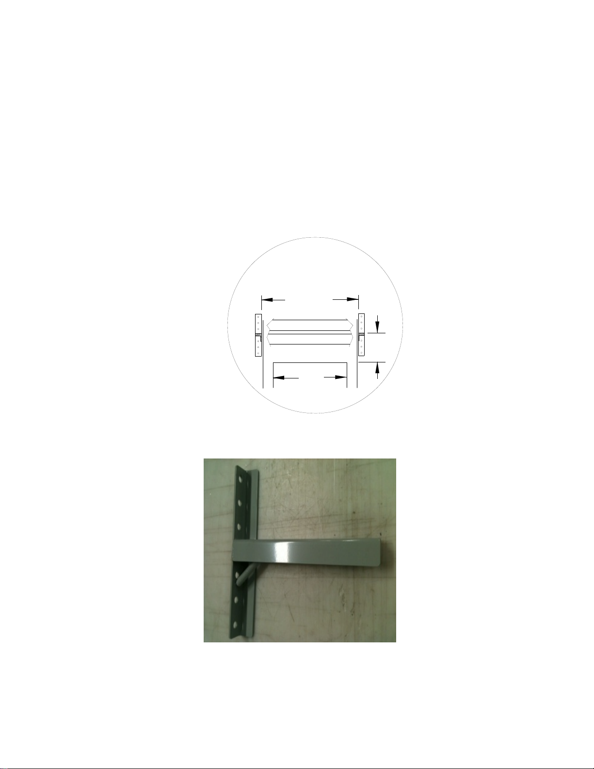
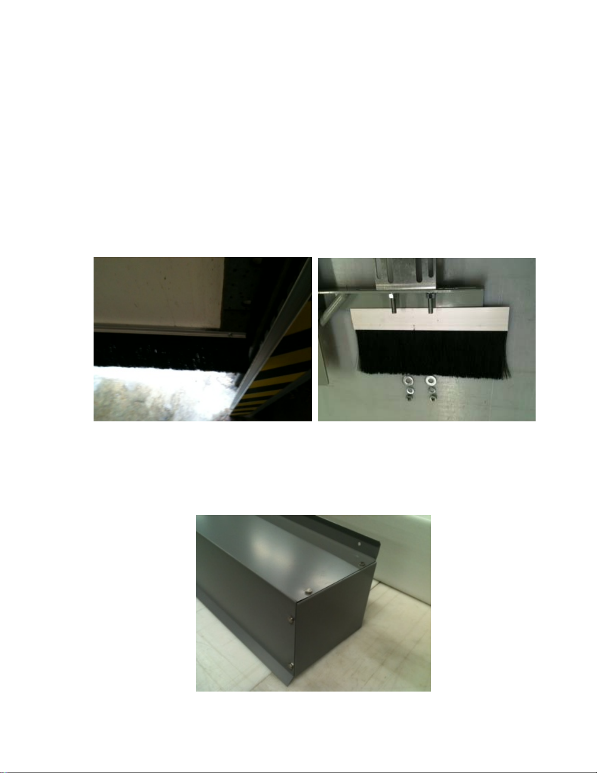
Splice Plate Roll Cover Bracket
If your Roll Cover comes in multiple pieces a Splice Plate is provided, as shown, to connect the
Roll Cover sections together. On wider Roll Covers, support brackets are provided as shown.
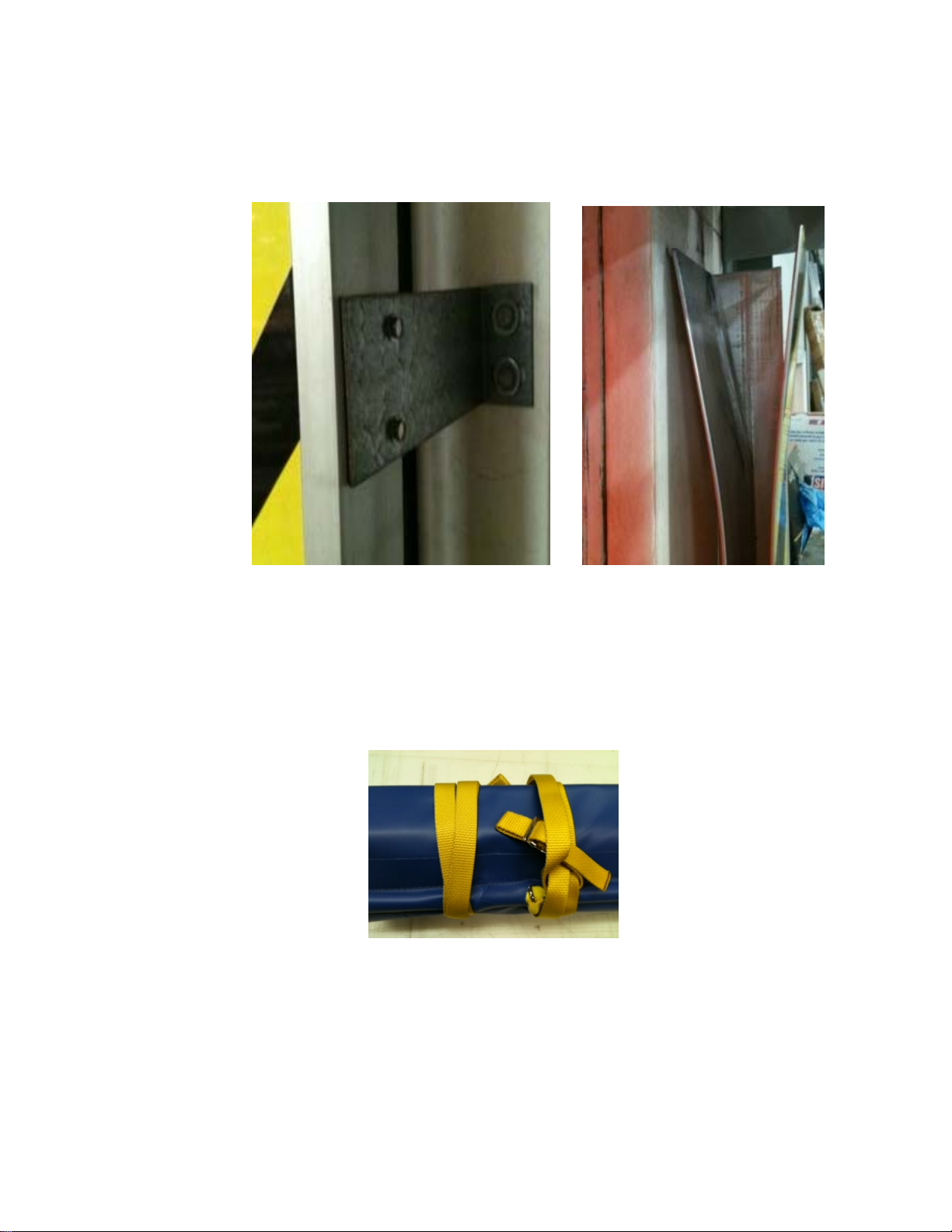
The Roll Cover Brackets should be mounted to the wall to support the weight of the Roll Cover.
They would be installed prior to installing the Roll as in section 3. They should be mounted so
that the Roll Cover will be level when installed. They should be mounted near each end of the
Roll Cover location and then spaced at approximately 24” apart. The Roll Cover is then lifted
onto the installed support brackets and secured to the wall as normal. The Roll Cover does not
attach to the support brackets, just to the wall. Any openings in the end caps, for shafts etc., are
to be done by the installer on site.
10. Final Assembly -
Go back and recheck all fasteners on the door assembly for tightness
Confirm correct opening and closing positions as well as spring tension
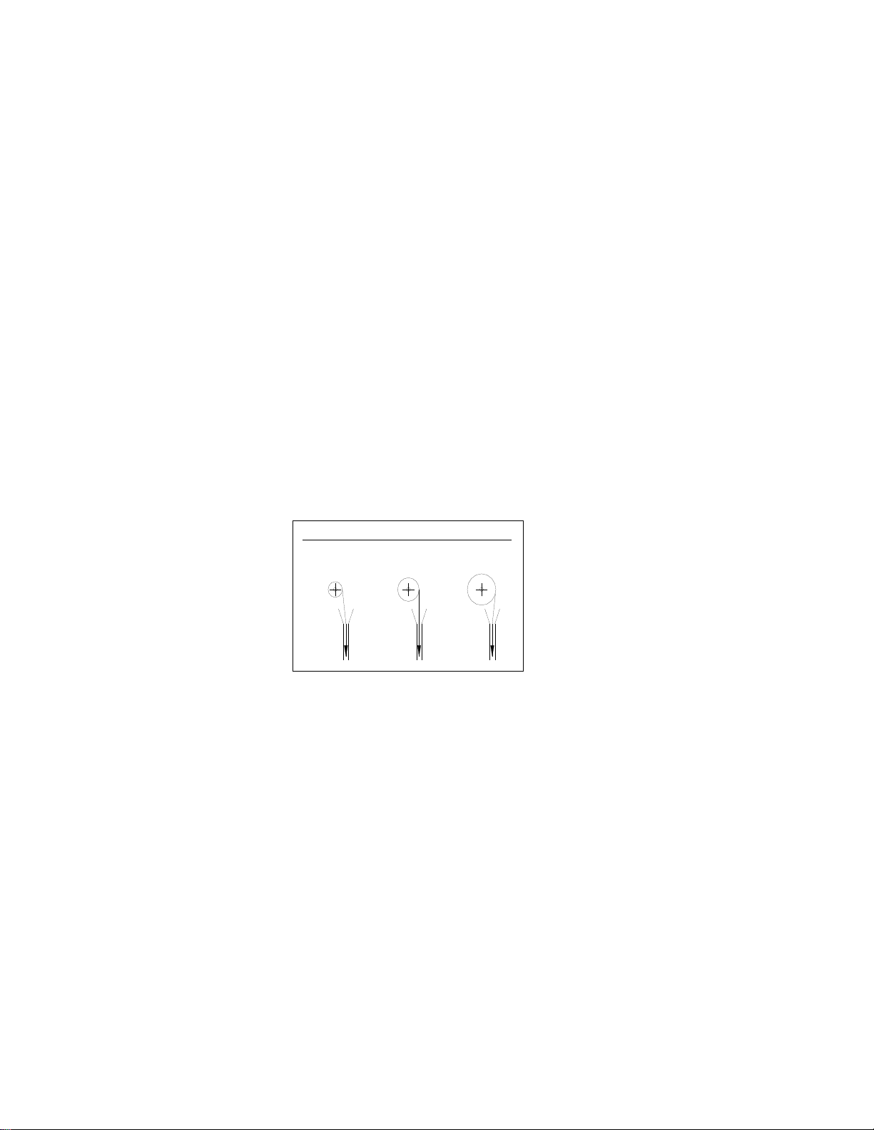
Confirm curtain to guide track clearances per section 7. Be sure that guide tracks
are clean and grease free inside and out.
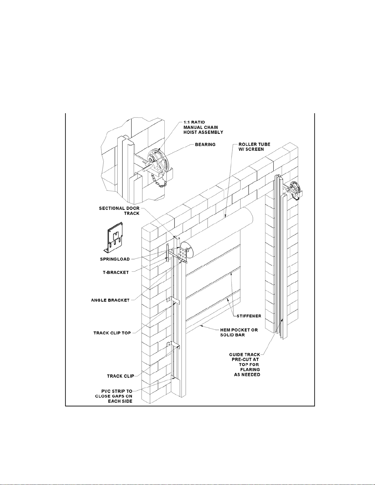
Install Black Vinyl (PVC) side panels (if supplied). These panels close in the gap
between the Guide Track and the wall, see diagram on page 1. The side panel
attaches to the Guide Track with installed Velcro and the installer attaches it to
the wall in an appropriate manner
Make sure end user is familiar with operation and has all manuals
DuraShield Installation Manual
Chain Hoist – Inside Standoff – Da-lite Springtube
Chase Doors Inc. 800-543-4455 8/12
DuraShield Installation Manual RB0371
Page 11

This manual suits for next models

2

Popular Chain Hoist manuals by other brands

Molnar 11 Series Installation, operation & maintenance manual

Molnar

Molnar 11 Series Installation, operation & maintenance manual

CM Lodestar Series Installation operating & maintenance manual

CM

CM Lodestar Series Installation operating & maintenance manual

KITO Chain Sling 100 owner's manual

KITO

KITO Chain Sling 100 owner's manual

Ingersoll-Rand SM Series Installation and operation manual

Ingersoll-Rand

Ingersoll-Rand SM Series Installation and operation manual

MODE V6 user manual

MODE

MODE V6 user manual

Lux Tools ESZ-100/200-A Original instructions

Lux Tools

Lux Tools ESZ-100/200-A Original instructions

Coffing Hoists ESC-680-1 Operating & maintenance instructions

Coffing Hoists

Coffing Hoists ESC-680-1 Operating & maintenance instructions

Comeup DH-300A quick start guide

Comeup

Comeup DH-300A quick start guide

Tractel Bravo AC Operation and maintenance manual

Tractel

Tractel Bravo AC Operation and maintenance manual

Parkside PKZ 1000 A1 Operating and safety instructions

Parkside

Parkside PKZ 1000 A1 Operating and safety instructions

SVERO 15 Series User instructions

SVERO

SVERO 15 Series User instructions

Endo EHL-05TS, EHL-1TW instruction manual

Endo

Endo EHL-05TS, EHL-1TW instruction manual

POWERTEX Lashing Chain PLC Instructions for use

POWERTEX

POWERTEX Lashing Chain PLC Instructions for use

Tractel Tralift Cleantech Installation, operating and maintenance manual

Tractel

Tractel Tralift Cleantech Installation, operating and maintenance manual

Jet JWS Series Operating instructions and parts manual

Jet

Jet JWS Series Operating instructions and parts manual

Sumake SA-22030 Operation manual

Sumake

Sumake SA-22030 Operation manual

Tractel bravo Series Operating and maintenance instruction

Tractel

Tractel bravo Series Operating and maintenance instruction

POWERWINCH H500 operating instructions

POWERWINCH

POWERWINCH H500 operating instructions

manuals.online logo
manuals.online logoBrands
  • About & Mission
  • Contact us
  • Privacy Policy
  • Terms and Conditions

Copyright 2025 Manuals.Online. All Rights Reserved.