Chauvet Professional C6 User manual

User Manual

Edition Notes
This User Manual includes a description of safety precautions, setup, installation, operation, and
maintenance for the CHAUVET® C6 video panel.
Trademarks
CHAUVET® is a registered trademark of Chauvet & Sons Inc. (d/b/a CHAUVET® or Chauvet). The
CHAUVET® logo in its entirety including the Chauvet name and the dotted triangle, and all other
trademarks on this manual pertaining to services, products, or marketing statements are owned or
licensed by Chauvet. Any other product names, logos, brands, company names, and other
trademarks featured or referred to within this document are the property of their respective
trademark holders.
Copyright Notice
Chauvet owns the content of this User Manual in its entirety, including but not limited to pictures,
logos, trademarks, and resources.
© Copyright 2014 Chauvet. All rights reserved.
Printed in P.R.C.
Electronically published by Chauvet in the United States of America.
Manual Use
Chauvet authorizes its customers to download and print this manual for professional information
purposes only. Chauvet expressly prohibits the usage, copy, storage, distribution, modification, or
printing of this manual or its content for any other purpose without its written consent.
Document Printing
For best results, print this document in color, on letter size paper (8.5 x 11 inches), double sided. If
using A4 paper (210 x 297 mm), configure your printer to scale the content accordingly.
Disclaimer
Chauvet believes that the information contained in this manual is accurate in all respects. However,
Chauvet assumes no responsibility for any error or omissions in this document. Chauvet reserves
the right to revise this document and to make changes from time to time in the content hereof
without obligation of Chauvet to notify any person or company of such revision or changes. This
does not constitute in any way a commitment by Chauvet to make such changes. Chauvet may
issue a revision of this manual or a new edition of it to incorporate such changes.
Document Revision
C6 User Manual, Rev. 2 is the second edition of this manual. Go to www.chauvetprofessional.com
for the latest version.
Author
Date
Editor
Date
L. Henry
08/22/14
A. Leon
09/17/14

Table Of Contents
1. Before You Begin......................................................................................................7
What Is Included..........................................................................................................................7
Unpacking....................................................................................................................................7
Symbols.......................................................................................................................................7
Safety Notes................................................................................................................................8
Expected LED Lifespan...............................................................................................................8
2. Introduction...............................................................................................................9
Product Description.....................................................................................................................9
Product Features......................................................................................................................9
Required Accessories ..............................................................................................................9
Optional Accessories................................................................................................................9
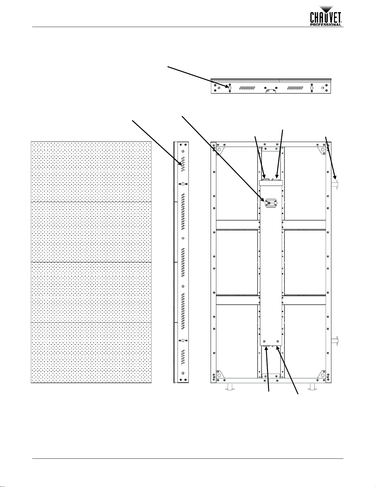
Product Overview......................................................................................................................10
Product Dimensions ..................................................................................................................11
3. Setup And Installation............................................................................................12
AC Power ..................................................................................................................................12
AC Plug ..................................................................................................................................12
Power Linking............................................................................................................................13
Power Linking Diagram ..........................................................................................................13
Signal Connection .....................................................................................................................14
Signal Connection Diagram....................................................................................................14
Mounting....................................................................................................................................15
PVP™ Rig Kit............................................................................................................................15
PVP™ Rig Kit Diagram ..........................................................................................................15
M12 Inserts................................................................................................................................16
M12 Inserts Diagram..............................................................................................................16
Panel Configurations.................................................................................................................16
Panel Configurations Diagrams..............................................................................................17
Speego Bolts.............................................................................................................................18
Speego Bolt Diagram .............................................................................................................18
Installation Guidelines ...............................................................................................................18
4. Configuration And Operation.................................................................................19
Testing The Panels ...................................................................................................................19
LED Studio Software.................................................................................................................19
VIP™ Driver...............................................................................................................................19
Video System Products Used With C6......................................................................................19
5. Technical Information.............................................................................................20
Maintenance..............................................................................................................................20
Troubleshooting.........................................................................................................................20
6. Technical Specifications........................................................................................21
Dimensions And Weight............................................................................................................21
Electrical....................................................................................................................................21
Light Source ..............................................................................................................................21
Photo Optic................................................................................................................................21
Thermal .....................................................................................................................................21
Data Connections......................................................................................................................21
Ordering.....................................................................................................................................21
Return Policy and Procedure.....................................................................................22
Contact Us...................................................................................................................23

1. Antes de Empezar...................................................................................................24
Qué va Incluido..........................................................................................................................24
Desembalaje..............................................................................................................................24
Símbolos....................................................................................................................................24
Notas de Seguridad...................................................................................................................25
Vida Útil Prevista del LED.........................................................................................................25
2. Introducción............................................................................................................26
Descripción del Producto ..........................................................................................................26
Características del Producto ..................................................................................................26
Accesorios Necesarios...........................................................................................................26
Accesorios Opcionales...........................................................................................................26
Visión General del Producto......................................................................................................27
Dimensiones del Producto ........................................................................................................28
3. Montaje e Instalación..............................................................................................29
Corriente Alterna .......................................................................................................................29
Enchufe CA ............................................................................................................................29
Alimentación en Cadena ...........................................................................................................30
Diagrama de Alimentación en Cadena ..................................................................................30
Conexión de Señal....................................................................................................................31
Diagrama de Conexión de Señal ...........................................................................................31
Montaje......................................................................................................................................32
PVP™ Rig Kit............................................................................................................................32
Diagrama del PVP™ Rig Kit...................................................................................................32
Inserciones M12........................................................................................................................33
Diagrama de Inserciones M12 ...............................................................................................33
Configuraciones de los Paneles................................................................................................33
Diagramas de Configuraciones de los Paneles.....................................................................34
Tornillos Speego........................................................................................................................35
Diagrama de Tornillo Speego.................................................................................................35
Pauta de Instalación..................................................................................................................35
4. Configuración y Funcionamiento ..........................................................................36
Probar los Paneles....................................................................................................................36
Software LED Studio.................................................................................................................36
VIP™ Driver...............................................................................................................................36
Productos de Sistema de Vídeo Usados con el C6..................................................................36
5. Información Técnica...............................................................................................37
Mantenimiento...........................................................................................................................37
Resolución de Problemas .........................................................................................................37
6. Especificaciones Técnicas.....................................................................................38
Dimensiones y Peso..................................................................................................................38
Eléctricas...................................................................................................................................38
Fuente de luz.............................................................................................................................38
Óptica foto.................................................................................................................................38
Térmicas....................................................................................................................................38
Conexiones de datos.................................................................................................................38
Pedidos......................................................................................................................................38
Política y Procedimiento de Devoluciones................................................................39
Contacto ......................................................................................................................40

1. Avant de Commencer.............................................................................................42
Contenu.....................................................................................................................................42
Déballage ..................................................................................................................................42
Symboles...................................................................................................................................42
Consignes de Sécurité ..............................................................................................................43
Durée de Vie des LEDs.............................................................................................................43
2. Introduction.............................................................................................................44
Description de l'Appareil............................................................................................................44
Caractéristiques de l'Appareil.................................................................................................44
Accessoires Nécessaires .......................................................................................................44
Accessoires Optionnels..........................................................................................................44
Vue d'Ensemble du Produit.......................................................................................................45
Dimensions de l'Appareil...........................................................................................................46
3. Configuration et Installation...................................................................................47
Alimentation CA.........................................................................................................................47
Prise CA .................................................................................................................................47
Chaînage Électrique..................................................................................................................48
Schéma de chaînage électrique.............................................................................................48
Connexion du Signal .................................................................................................................49
Schéma des Connexions de Signal .......................................................................................49
Installation .................................................................................................................................50
Kit d'Installation PVP™..............................................................................................................51
Diagramme du Kit d'Installation PVP™..................................................................................51
Inserts M12................................................................................................................................52
Diagramme des Inserts M12..................................................................................................52
Configurations du Panneau.......................................................................................................52
Diagrammes des Configurations de Panneaux......................................................................53
Boulons Speego........................................................................................................................54
Diagramme d'un Boulon Speego ...........................................................................................54
Instructions pour l'installation ....................................................................................................54
4. Configuration et Utilisation....................................................................................55
Test des Panneaux ...................................................................................................................55
Logiciel LED Studio...................................................................................................................55
VIP™ Driver...............................................................................................................................55
Appareils de Système Vidéo Utilisés avec le C6 ......................................................................55
5. Informations Techniques .......................................................................................56
Entretien....................................................................................................................................56
Dépannage................................................................................................................................56
6. Spécifications Techniques.....................................................................................57
Dimensions et Poids..................................................................................................................57
Alimentation Électrique..............................................................................................................57
Source Lumineuse ....................................................................................................................57
Optique Photo............................................................................................................................57
Thermique .................................................................................................................................57
Connections de Données..........................................................................................................57
Commande................................................................................................................................57
Politique et Procédure de Retour...............................................................................58
Nous Contacter ...........................................................................................................59

1. Voordat u begint .....................................................................................................61
Wat is er inbegrepen .................................................................................................................61
Uitpakken...................................................................................................................................61
Symbolen...................................................................................................................................61
Veiligheidsinstructies.................................................................................................................62
Verwachte levensduur van de LED-lamp..................................................................................62
2. Inleiding...................................................................................................................63
Productbeschrijving...................................................................................................................63
Producteigenschappen...........................................................................................................63
Vereiste accessoires ..............................................................................................................63
Optionele accessoires............................................................................................................63
Productoverzicht........................................................................................................................64
Afmetingen van het product ......................................................................................................65
3. Opstelling en installatie..........................................................................................66
AC-stroom .................................................................................................................................66
AC-stekker..............................................................................................................................66
Power Linking............................................................................................................................67
Power Linking-diagram...........................................................................................................67
Signaalverbinding......................................................................................................................68
Signaalverbindingsdiagram....................................................................................................68
Montage.....................................................................................................................................69
PVP™-opbouwset.....................................................................................................................69
PVP™-opbouwsetdiagram.....................................................................................................70
M12-inzetstukken ......................................................................................................................71
M12-inzetstukdiagram............................................................................................................71
Paneelconfiguraties...................................................................................................................71
Paneelconfiguratiediagrammen..............................................................................................72
Speego-bouten..........................................................................................................................73
Speego-bout diagram.............................................................................................................73
Installatierichtlijnen....................................................................................................................73
4. Configuratie en bediening......................................................................................74
Testen van de panelen..............................................................................................................74
LED Studio-software .................................................................................................................74
VIP™ Driver...............................................................................................................................74
Videosysteemproducten die worden gebruikt met C6...............................................................74
5. Technische informatie............................................................................................75
Onderhoud.................................................................................................................................75
Problemen oplossen..................................................................................................................75
6. Technische Specificaties .......................................................................................76
Afmetingen en gewicht..............................................................................................................76
Elektrisch...................................................................................................................................76
Lichtbron....................................................................................................................................76
Foto-optisch...............................................................................................................................76
Thermisch..................................................................................................................................76
Gegegevensaansluitingen.........................................................................................................76
Bestellen....................................................................................................................................76
Retourbeleid en -procedure........................................................................................77
Neem contact op.........................................................................................................78

Before You Begin
C6 User Manual Rev. 2 Page 7 of 80
1.Before You Begin
What Is Included
•4 C6 panels
•1 Neutrik® powerCON® power cord
•4 Neutrik® powerCON® power linking cords
•4 Neutrik® etherCON® signal linking cords
•Warranty card
•User Manual
Unpacking
Carefully unpack the C6 panels and check that all the parts are in the package, and are in good
condition.
If the box, or any of the contents, appear damaged from shipping, or show signs of mishandling,
save all the packaging and file a claim with the carrier immediately, do not notify Chauvet. Failure to
report damage to the carrier immediately, or failure to have all the packaging available for
inspection, could invalidate the claim.
For other issues, such as missing components or parts, damage not related to shipping, or
concealed damage, file a claim with Chauvet within 7 days of delivery. For information on contacting
Chauvet, see Contact Us at the end of this manual.
Symbols
Symbols
Meaning
Critical installation, configuration, or operation information. Failure to comply with this
information may cause the product not to work, damage third-party equipment, or
cause harm to the operator.
Important installation or configuration information. Failure to comply with this
information may keep the product from working.
Useful information.

Before You Begin
Page 8 of 80 C6 User Manual Rev. 2
Safety Notes
Please read the following Safety Notes carefully before starting to work with the product. These
notes provide important safety information about the installation, usage, and maintenance.
•Always connect the product to a grounded circuit.
•Make sure the power cord is not crimped or damaged.
•Always connect this product to a power source with the proper voltage as listed on the
product sticker.
•Do not operate the product if you see damage on the housing, LED strips, or cables.
•This product is for indoor use only! It is rated IP40. Do not expose the product to rain or
moisture.
•Always disconnect the product form the power source before cleaning it.
•To eliminate unnecessary wear and improve its lifespan, during periods of non-use
completely disconnect the product from power via breaker or by unplugging it.
•Never disconnect the product from the power source by pulling or tugging on the cord.
•If mounting the product overhead, always secure it using a safety cable.
•Make sure there are no flammable materials close to the product when it is operating.
•CAUTION: When transferring product from extreme temperature environments, (e.g.
cold truck to warm humid ballroom) condensation may form on the internal electronics of
the product. To avoid causing a failure, allow product to fully acclimate to the
surrounding.
•Never connect the product to a dimmer or a rheostat.
•Always install the product in a location with adequate ventilation.
•Do not operate the product in an ambient temperature higher than 104 °F (45 °C).
•This product contains no user-serviceable parts. Any reference to servicing in this User
Manual will only apply to properly trained Chauvet certified technicians. Do not open the
housing or attempt any repairs.
•All applicable local codes and regulations apply for proper installation of this product.
•In the event of a serious operating problem, stop using the product immediately.
•Any damages caused by manual modifications are not subject to warranty. Chauvet will
not accept liability for damage caused by unauthorized modifications or not observing
the safety warnings and instructions in the manual.
If the product requires repair contact Chauvet. For more information, see Return Policy and
Procedure and Contact Us.
Expected LED Lifespan
LEDs gradually decline in brightness over time, primarily because of the heat of their operating
temperature and using. When LEDs are clustered, as they are in video panels, they generate higher
operating temperature than they do when not clustered. Using clustered LEDs at their fullest
intensity reduces the LEDs’ lifespan. The C6 panels have a thermal management system designed
to overcome this and provide the most brilliant image possible with the longest LED lifespan. The
C6 panel’s LED lifespan is 50,000 hours. However, the LED lifespan can be extended even further
by increasing the ventilation around the panels and keeping the ambient temperature to an optimal
operating range. In addition, limiting the overall projection intensity may also help to extend the
LEDs’ lifespan.

Introduction
C6 User Manual Rev. 2 Page 9 of 80
2.Introduction
Product Description
C6 is a 6.25 mm pixel pitch LED video panel designed specifically for permanent installation. It uses
black face SMD 3528 LEDs for superb contrast. It is quiet, lightweight, measures 1 x 0.5 m and is
modularly designed for easy installation and customization.
The C6 power and signal connections are compatible with the CHAUVET® VIP™ lines, so C6 video
walls and PVP™ video walls can be managed with the same control source.
C6 panels are operated with the VIP™ line of signal distribution and control products, and
configured with the CHAUVET® LED Studio software running on a PC. For more information about
the VIP™ line or LED Studio, download the User Manuals from the Chauvet website at
http://www.chauvetlighting.com/product-manuals-literature/.
Product Features
•6.25 mm pixel pitch and a 140° viewing angle for a detailed and easily viewed image
•Black face SMD 3528 LEDs for superb contrast
•Tight LED binning for consistent color rendering across panels
•Solid, lightweight, modular construction for flexible configuration
•Compatibility with PVP™ Rig Kit for suspended mounting of up to 10 panels per Rig Kit
•M12 threaded inserts for easy and secure permanent installation
•Fanless operation for silent operation
•Fully compatible with VIP™ Driver, VIP™ Signal Distributor, and VIP™ Media Server Pro
Required Accessories
•VIP™ Driver (required)
•LED Studio (required)
Optional Accessories
•VIP™ Signal Distributor (required for operating more than 24 panels)
•Signal cables (Neutrik® etherCON® Signal Extensions)
oETHERCON18IN
oETHERCON5FT
oETHERCON10FT
•Power cables (Neutrik® powerCON® Extension)
oPOWERCONEXT18IN
oPOWERCONEXT5FT
oPOWERCONEXT10FT
oPOWERCONEXT25FT

Introduction
Page 10 of 80 C6 User Manual Rev. 2
Product Overview
Power In
Signal
In/Out
Power Out
Signal
In/Out
Test Button
Signal Indicator
Power Indicator
Front
Back
Long
Edge
Short Edge
Male Speego
Connectors (x4)
Female Speego
Connectors (x4)
Ventilation Slots
5 Per Long Edge
2 Per Short Edge

Introduction
C6 User Manual Rev. 2 Page 11 of 80
Product Dimensions

Setup And Installation
Page 12 of 80 C6 User Manual Rev. 2
3.Setup And Installation
AC Power
Each C6 panel has an auto-ranging power supply that works with an input voltage range of
100 to 240 VAC, 50/60 Hz. To determine the power requirements for C6, refer to the label affixed to
the product or Technical Specifications.
The listed rating indicates the maximum current draw during normal operation. For more
information, download Sizing Circuit Breakers from the Chauvet website at
www.chauvetprofessional.com.
•Always connect this product to a properly grounded and protected circuit.
•Never connect this product to a rheostat or dimmer.
•To eliminate unnecessary wear and improve its lifespan, during periods of non-use
completely disconnect the product from power via breaker or by unplugging it.
AC Plug
The included power input cord has a Neutrik® powerCON® connector on one end to connect to the
C6, and an Edison plug at the other end to connect to power. Each C6 panel comes with a Neutrik®
powerCON® power-linking cord to connect power between panels.
Use the table below as a reference when wiring a new plug.
Connection
Wire (U.S.)
Wire (Europe)
Screw Color
AC Live
Black
Brown
Yellow or Brass
AC Neutral
White
Blue
Silver
AC Ground
Green/Yellow
Green/Yellow
Green

Setup And Installation
C6 User Manual Rev. 2 Page 13 of 80
Power Linking
The C6 panels have Neutrik® powerCON® Power In and Power Out sockets placed to make power
linking easy. Do not power link more than
•12 panels at 120 V,
•21 panels at 208 V, or
•22 panels at 230 V.
Power Linking Diagram
Power Source
Additional
C6 Panels

Setup And Installation
Page 14 of 80 C6 User Manual Rev. 2
Signal Connection
The C6 panels receive video signal from the VIP™ Driver via a Neutrik® etherCON® cable, which
must be no more than 100 m long. The Neutrik® etherCON® cable goes from the U MAIN OUT
Neutrik® etherCON® port of the VIP™ Driver into one of the video panels. Neutrik® etherCON®
power-linking cords link the other panels together.
The signal cables must be run from panel to panel in the order in which they will be mapped in the
LED software. The Neutrik® etherCON® signal ports on the panels can be used as either input or
output ports, so signal can transmit in either direction.
After all the panels are connected, the last linked panel will have an empty signal port that can be
used to create a back-up signal infrastructure. To do this, run a Neutrik® etherCON® cable from the
empty Neutrik® etherCON® port of the last panel to the D BACK UP Neutrik® etherCON® port of
the VIP™ Driver.
Signal Connection Diagram
•Signal transmission can be in either direction, so the first or the last panel in the
signal link can be connected to the VIP™ Driver.
From VIP™ Driver
U MAIN OUT Port
To VIP™ Driver D BACK UP Port

Setup And Installation
C6 User Manual Rev. 2 Page 15 of 80
Mounting
The C6 panels are constructed of aluminum alloy and stainless steel so each panel is stable and
lightweight. The C6 panels have open backs to provide better ventilation when permanently
installed in a venue, or built into a piece of scenery.
C6 panels can be mounted using the PVP™ Rig Kit, which is sold separately. For more information,
see the Chauvet website at http://www.chauvetlighting.com/pvp-rigging-kit.html.
C6 panels can also be mounted directly to any surface using M12 bolts into the inserts at each
corner of the panel.
Consider the following when designing an installation of the C6 panels:
•Airflow behind the panels
•Load capacity of the structures to which the panels will be attached
•Access to the power and signal cable connections
•Visibility of the signal and power indicators
•Ambient temperature of the location
See Technical Specifications for specific weight and temperature requirements.
Consult a structural engineer to determine safe load ratings based on your specific
application.
PVP™ Rig Kit
The CHAUVET® PVP™ Rig Kits attach to the top of both corners of the panels’ narrow ends, with
one Rig Kit joining adjacent panels at their adjoining corners. The PVP™ Rig Kit consists of a single
bracket with 2 male speego bolts on the bottom and an M12-size hole at the top.
The speego bolts fit into the female speego connectors on the C6 panel. At the top of the PVP™
Rig Kit is an M12-size hole, which can be used with an M12 bolt, to attach the PVP™ Rig Kit to a
clamp or to a structure. The speego bolts are placed so that the PVP™ Rig Kit spans 2 panels. To
hang a single panel use PVP™ Rig Kits on both ends of the panel.
The panels themselves can be connected to each other to create any number of shapes. See Panel
Configurations.
Each PVP™ Rig Kit can bear the weight of up to 10 panels hung vertically.
PVP™ Rig Kit Diagram
PVP™ Rig Kit Ships
With A Removable
Clamp
PVP™ Rig Kit
Attaches To
A Structure
Male Speegos on the PVP™ Rig Kits
Go Into the Female Speegos On Top of the Panels
Side Speego Connectors Align Panels
Tops of Panels

Setup And Installation
Page 16 of 80 C6 User Manual Rev. 2
M12 Inserts
The M12 inserts are at each corner on the back of the C6 panel, to provide a mechanism to mount
the panel directly onto a flat surface. When mounting the panel on a flat surface be sure to leave
enough room to allow adequate airflow and a way to see the signal indicator lights. Insert a
separator at each corner between the panel and the surface, with an opening in the center through
which the signal and power indicators remain visible.
The number of panels that can be mounted to any surface depend on the load bearing capacity of
the surface. It is optimal to connect the panel to the surface wherever there is an M12 insert.
M12 Inserts Diagram
4
Panel Configurations
The C6 panels can be connected in any number of configurations using the speego connections on
the edges. However, the panels must all be oriented the same way because they are made up of 4
subpanels, each measuring 0.25 x 0.5 m. These subpanels cannot be mapped differently within the
larger configuration of panels. See Panel Configurations Diagrams.
The expected orientation has the panels vertically oriented because vertical orientation works with
any content manager or switcher. The alternate orientation, with the panels oriented horizontally
requires a content manager or switcher that can rotate images. See Orientation.
The C6 panels must all be mounted with the same orientation. The panels do not need to be aligned
by subpanel, but each row of pixels must be aligned. The panels and subpanels can be
mismatched. See Lining Up Pixels.
M12 Bolt Inserts
M12 Bolts
M12 Bolts
Optional Spacers For Ventilation
Mounting
Structure

Setup And Installation
C6 User Manual Rev. 2 Page 17 of 80
Panel Configurations Diagrams
Orientation
Lining Up Pixels
Horizontal Orientation
Requires Rotated Content
Vertical Orientation is the Expected Orientation
And Does Not Require Rotated Content
DO NOT ConfigurePanels
in a Mixed Orientation
Individual
Subpanels
The Pixels on Either Side of the Panels
Should Meet at yhe Seam; However, the
Subpanels Do Not Need to Align
Subpanels Can Be Offset;
However, Pixels Must Align
One Panel

Setup And Installation
Page 18 of 80 C6 User Manual Rev. 2
Speego Bolts
Speego bolts are very strong steel posts with locking bars at the ends and power-spring tightening
mechanisms. They create a temporary attachment to allow for alignment of the LEDs, and then a
firm and precise connection so the pixels remain aligned properly and create a seamless image.
To attach a speego bolt, do the following:
1. Hold the spring knob and insert the locking bar into the inset.
2. Twist the spring knob counter-clockwise until the locking bar locks into place. This step holds the
panels in place to allow precise alignment of the panels.
3. Align the panels using the LEDs as a reference.
4. Twist the tightening knob clockwise to tighten the connection completely.
To detach a speego bolt, do the following:
1. Twist the tightening knob counter-clockwise to loosen the connection.
2. Twist the spring knob clockwise until the locking bar pops out of place.
Speego Bolt Diagram
Installation Guidelines
•Check that all the parts are in the package.
•Make sure all the required and optional accessories for mounting and operation are available for
use.
•Power and test each panel. For more information, see Testing the Panels.
•When building a suspended installation, work from the top down.
•When building an installation mounted on a surface, align and tighten the panels before affixing
them to the surface.
Tightening Knob
Locking Bar
Spring Knob
Spring
Speego Inset

Configuration And Operation
C6 User Manual Rev. 2 Page 19 of 80
4.Configuration And Operation
Configuration and operation of the C6 panels is done with the LED Studio software, and either the
VIP™ Media Server Pro and VIP™ Signal Processor, or the media server software of your choice.
The C6 panels require 1 VIP™ Driver for each 102 C6 panels.
Video systems vary in size and complexity. The C6 panels can be used in a simple system with a
media server and a VIP™ Driver to panels in a rectangular connection; or the panels can be part of
a complex system with multiple inputs to panels in a fragmented or rotated connection, as shown in
the Panel Configurations Diagrams.
Regardless of the panel connection or the system complexity, LED Studio and the VIP™ Driver are
required to configure and use the panels. For more information about LED Studio see the User
Manual available from the Chauvet website at http://www.chauvetlighting.com/product-manuals-
literature/.
Testing The Panels
To test the C6 panel, press <TEST> the back of the panel. This test runs a program that checks the
C6 circuitry and all the LEDs.
LED Studio Software
LED Studio is an easy-to-use mapping tool. It runs on a PC and works seamlessly with the VIP™
Driver so that the content can be adjusted to display properly on any connection pattern of C6
panel. For more information about LED Studio, see the User Manual available from the Chauvet
website at http://www.chauvetlighting.com/product-manuals-literature/.
VIP™ Driver
VIP™ Driver is the hardware interface between LED Studio, or the video input source, and the C6
panels. For more information about the VIP™ Driver see the User Manual available from the
Chauvet website at http://www.chauvetlighting.com/product-manuals-literature/.
Video System Products Used With C6
Item
Description
Item Code
Item Number
VIP™ Driver (required) Interface between LED Studio or signal
input and the C6 panels 99090575 VIPDRIVER
LED Studio (required) Software that maps the C6 panels.
Requires a PC to operate.
VIP™ Signal Distributor
Signal booster for over 24 panels
99090576
VIPSIGDISTRO
PVP™ Rig Kit Hardware for suspended mounting 20090598 PVP-RK
Neutrik®
etherCON® to etherCON®
etherCON® Signal Extension, 18 in
etherCON® Signal Extension, 5 ft
etherCON® Signal Extension, 10 ft
19090363
19090364
19090365
ETHERCONEXT18IN
ETHERCONEXT5FT
ETHERCONEXT10FT
Neutrik®
powerCON® to
powerCON®
powerCON® Extension, 18 in
powerCON® Extension, 5 ft
powerCON® Extension, 10 ft
powerCON® Extension, 25 ft
19110372
19110373
19110374
19110375
POWERCONEXT18IN
POWERCONEXT5FT
POWERCONEXT10FT
POWERCONEXT25FT
VIP™ Media System Pro
Video server with ArKaos MediaMaster
VIPCOMP2

Technical Information
Page 20 of 80 C6 User Manual Rev. 2
5.Technical Information
Maintenance
To maintain optimum performance and minimize wear, turn the C6 panels off when not actively
being used and completely disconnect from power. Keep the environment around them free of dust,
dirt, water, and extreme temperatures.
The C6 panels should be cleaned at least once a month. To prevent dust build-up from reducing
light output and overheating, follow these guidelines when cleaning the C6 panels:
1. Unplug the panel from power.
2. Wait until the panel is at room temperature.
3. Use a soft brush to remove dust collected on the external components.
4. Wipe the outside of the LED strips with a soft, lint-free cloth dampened with a solution of water
and detergent. Apply gentle pressure only.
5. Make sure all connections are thoroughly dry before reconnecting power and signal cables.
Always dry the external surfaces carefully after cleaning them.
Do not spin the cooling fans using compressed air because you could damage them.
Troubleshooting
Problem
Cause
Resolution
All panel LEDs are blinking Contact failure Fix the loose LEDs or try re-plugging
LEDs on a specific panel are not on
Power cable not seated properly
Reseat power cable
All LEDs do not light Input cables connected incorrectly
Find the incorrectly connected cables
and reconnect properly
Does not power up
(LED power indicator does not
light during “self-test”)
No power
Contact Chauvet for repair
Loose or damaged power cord
Faulty power connection inside the
C6
Faulty external power supply
C6 displays no images or spotted
images Loose or damaged signal cable
Disconnect and reconnect the signal
cable, or replace the cable
Table of contents
Languages:
Other Chauvet Professional Industrial Monitor manuals
Popular Industrial Monitor manuals by other brands

elrest
elrest eVISIO PTE715 Package leaflet

HEIDENHAIN
HEIDENHAIN ND 221 manual

Christie
Christie FHD551-X Series Schematic diagrams

Autonics
Autonics GP Series Technical support manual

Absen
Absen AW Series user manual

Industrial Automation and Enclosures Inc.
Industrial Automation and Enclosures Inc. RLCD170 user manual

Advantech
Advantech FPM-2120G Series user manual

CyberView
CyberView RP-HF821 user manual

Christie
Christie MicroTiles user manual

Hope Industrial Systems
Hope Industrial Systems HIS-ML21-*** D series user manual

Matrix Orbital
Matrix Orbital MOP-TFT480272-43A-BLM-CTB Hardware manual

Pentair
Pentair Raychem ECW-GF-DP Installation and operating instructions