Page 3 of 33
F2 User Manual Rev. 1
Introduction
2. Introduction
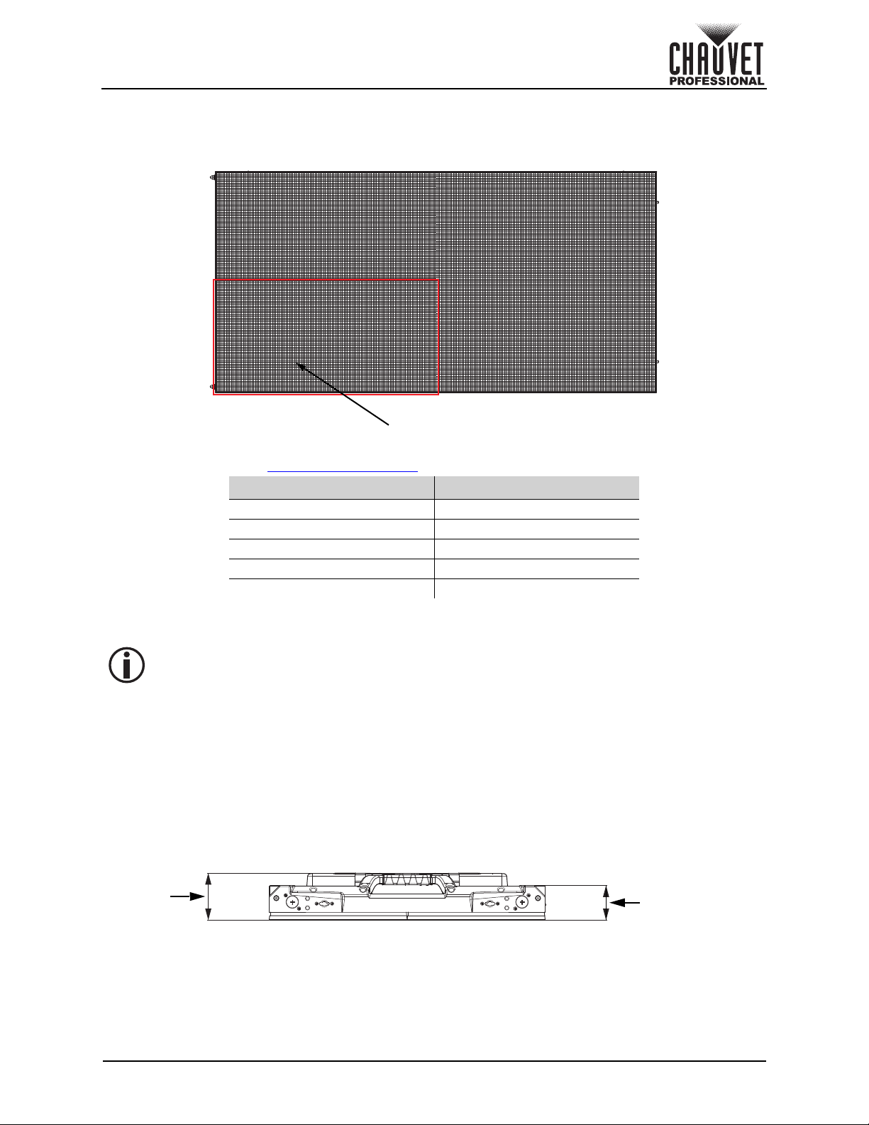
Product Description
The F2 is a 2.9 mm pixel pitch LED video panel equipped with a high contrast 1,500 NITS and a refresh
rate of 3,840 Hz for crisp, high quality, imagery. This high-performance video panel is ideal for corporate
events with text, high-res IMAG and any space with a shorter viewing distance. The F2 features a light-
weight die-cast magnesium housing and magnetic assisted hanging. The magnetic LED modules are also
both front and rear serviceable.
Features
• 2.9 mm pitch high resolution indoor video panel works with the VIP Drive 43Nova2, using the
Novastar control protocol
• High quality black body LEDs accurately reproduce video at 16-bit grayscale, operating on the A5s
receiver card from Novastar (18-bit available)
• High performance digital LED drivers deliver 3840Hz refresh rate and a clear, vibrant image
• Uses specialized LED dimming control via S-PWM (Scrambled Pulse-Width Modulation), which
enhances on-camera performance.
• Intelligent, high speed magnetic LED modules with dedicated memory stores factory calibration,
ensuring optimal image quality, color uniformity, and simplifies maintenance by making service fast
and easy
• 1,000 x 500 x 82.5 mm, 30 lb (13.6 kg) magnesium die-cast housing (500 x 500 mm available)
makes this product among the lightest and slimmest in its class without compromising strength,
capable of hanging up to 23 panels vertically safely
• Specialized frame design allows for overhead hanging, ground stacking, and wall mounting
maximizing installation flexibility and aftermarket front and rear service; simply push out modules
from the rear using the handles, or use the included service tool from the front.
• Front LED surface protective design features prevent damage when handling: 4x stainless steel
standing feet to keep the LEDs from touching the floor, specialized LED board design to improve
impact resistance up to 3x that of other panels, and resilient led mask design to optimize image
viewing angle and uniformity without exposing the LEDs to front or side impacts
• Strong, magnetic assisted hanging makes setting up the panels fast and easy with a minimal crew
• Optimized heat dissipation ensures an even color across the F2
• Dual power supplies increase the stability of the system
• Cable management solutions include angled connectors on panels for easy operation, long cables
which can connector horizontally or vertically, and handles on the bottoms of each panel to organize
cables and keep them neat
• Ground support system, and concave curving hardware available
Required Accessories
• Required Software: Nova LCT Mars
• Controller (required): VIP Drive 43Nova 2 or VIP Drive 83R Nova
• Accessories (required): VIP Driver
• Compatible Mounting Options: F-series Rig Bar (0.5 m and 1 m) (overhead hanging), M10 Bolt/
Clamp (front mounting), M12 Bolt/Clamp (rear mounting)
Optional Accessories
• ArKaos Media Master Express + KN software
• DRB-100CM, DRB-50CM, and DRB-CurveX2
• VIDTOURCART
• GROUNDSUPPORT2KIT
• VIDCURVEKIT
Available Signal and Power Cables
Signal cables (Neutrik®etherCON®CAT6 Signal Extensions)
• ETHERCONEXT18IN
• ETHERCONEXT5FT
• ETHERCONEXT10FT
• ETHERCONEXT25FT
• ETHERCONEXT50FT
Power cables (Neutrik®powerCON®Power Extensions)
• POWERCONEXT18IN
• POWERCONEXT5FT
• POWERCONEXT10FT
• POWERCONEXT25FT
• POWERCONEXT50FT