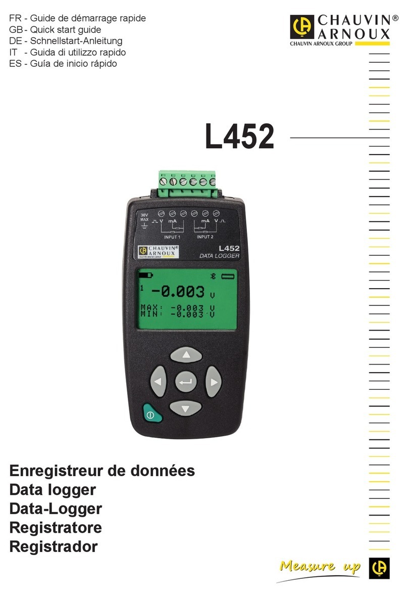
Chauvin Arnoux PEL 51 User manual

Power & Energy Logger
EN - User’s manual
PEL 51
PEL 52

2
Thank you for purchasing a PEL51 or PEL52 Power & Energy Logger.
For best results from your device:
read this user manual carefully, and
comply with the precautions for use.
Denition of measurement categories
Measurement category IV corresponds to measurements taken at the source of low-voltage installations.
Example: power feeders, meters and protection devices.
Measurement category III corresponds to measurements on building installations.
Measurement category II corresponds to measurements taken on circuits directly connected to low-voltage installations.
Example: power supply to electrical appliances and portable tools.
WARNING, risk of DANGER! The operator must refer to these instructions whenever this danger symbol appears.
Caution! Risk of electric shock. The voltage applied to parts marked with this symbol may be hazardous.
Equipment protected by double insulation.
Useful information or tip.
SD card.
The product has been declared recyclable after analysis of its life cycle in accordance with the ISO 14040 standard.
Chauvin Arnoux has adopted an Eco-Design approach in designing this appliance. Analysis of the complete lifecycle has
regulation requirements with respect to recycling and reuse.
The CE marking indicates compliance with the European Low Voltage Directive (2014/35/EU), the Electromagnetic
Compatibility Directive (2014/30/EU), the Directive on Radioelectric Equipment (2014/53/EU) and the Directive on the
Restriction of Hazardous Substances (RoHS, 2011/65/EU and 2015/863/EU).
particular as regards Low-Voltage Safety, Electromagnetic Compatibility, and the Restriction of Hazardous Substances.
The rubbish bin with a line through it indicates that, in the European Union, the product must undergo selective disposal
in compliance with Directive WEEE 2012/19/EU. This equipment must not be treated as household waste.

3
PRECAUTIONS FOR USE
This device complies with safety standard IEC/EN 61010-2-30 or BS EN 61010-2-030, the leads comply with IEC/EN 61010-031
or BS EN 61010-031 and the current sensors comply with IEC/EN 61010-2-032 or BS EN 61010-2-032 for voltages up to 600 V
in category III.
Failure to observe the safety instructions may result in electric shock, fire, explosion, and/or destruction of the device
and of the installations.
The operator and/or the responsible authority must carefully read and clearly understand the various precautions to be taken
in use. Sound knowledge and a keen awareness of electrical hazards are essential when using this instrument.
Use only the leads and accessories supplied. The use of leads (or accessories) of a lower voltage or category limits the voltage
or category of the combined device and leads (or accessories) to that of the leads (or accessories).
Before each use, check the condition of the insulation on the leads, housing, and accessories. Any item of which the insulation
is deteriorated (even partially) must be set aside for repair or scrapping.
Do not use the instrument on networks of which the voltage or category exceeds those mentioned.
Do not use the instrument if it seems to be damaged, incomplete, or poorly closed.
Use personal protection equipment systematically.
If the device is wet, dry it before connecting it.
All troubleshooting and metrological checks must be performed by competent and accredited personnel.

4
CONTENTS
1. GETTING STARTED ............................................................................................................................................................5
1.1. Delivery condition ........................................................................................................................................................5
1.2. Accessories .................................................................................................................................................................6
1.3. Spares .........................................................................................................................................................................6
1.4. Charging the battery ....................................................................................................................................................6
2. DEVICE OVERVIEW ............................................................................................................................................................7
2.1. Description...................................................................................................................................................................7
2.2. PEL51 and PEL52 .......................................................................................................................................................8
2.3. Terminal block..............................................................................................................................................................8
2.4. Back.............................................................................................................................................................................9
2.5. SD card slot .................................................................................................................................................................9
2.6. Set up ........................................................................................................................................................................10
2.7. Key functions .............................................................................................................................................................10
2.8. LCD display ...............................................................................................................................................................10
2.9. Memory card.............................................................................................................................................................. 11
3. OPERATION .......................................................................................................................................................................12
....................................................................................................................................12
...............................................................................................................................................13
3.3. Information.................................................................................................................................................................18
4. USE......................................................................................................................................................................................20
4.1. Distribution networks and connections of the PEL ...................................................................................................20
4.2. Recording ..................................................................................................................................................................21
4.3. Measured value display modes .................................................................................................................................21
5. PEL TRANSFER SOFTWARE ..........................................................................................................................................27
5.1. Functionalities............................................................................................................................................................27
5.2. Installing PEL Transfer ..............................................................................................................................................27
6. TECHNICAL CHARACTERISTICS ..................................................................................................................................29
6.1. Reference conditions.................................................................................................................................................29
6.2. Electrical properties ...................................................................................................................................................29
........................................................................................................................................35
6.4. Power supply .............................................................................................................................................................36
6.5. Environmental characteristics....................................................................................................................................37
.............................................................................................................................................................................37
6.7. Mechanical characteristics ........................................................................................................................................37
6.8. Electrical safety .........................................................................................................................................................37
6.9. Electromagnetic compatibility ....................................................................................................................................37
6.10. Radio emission ........................................................................................................................................................38
6.11. Memory card............................................................................................................................................................38
7. MAINTENANCE.................................................................................................................................................................39
7.1. Cleaning ....................................................................................................................................................................39
7.2. Battery .......................................................................................................................................................................39
.....................................................................................................................................................39
8. WARRANTY .......................................................................................................................................................................40
9. APPENDIX ..........................................................................................................................................................................41
9.1. Measurements...........................................................................................................................................................41
9.2. Measurement formulas..............................................................................................................................................42
9.3. Aggregation ...............................................................................................................................................................42
9.4. Supported electrical networks ...................................................................................................................................43
9.5. Values available.........................................................................................................................................................44
9.6. Values available.........................................................................................................................................................46
9.7. Glossary ....................................................................................................................................................................47
5
1. GETTING STARTED
1.1. DELIVERY CONDITION
Figure 1
No. Designation PEL51 PEL52
①PEL51 or PEL52 1 1
②Safety leads, 3 m, banana-banana, straight-straight. 1 red
1 black 3 blacks
③Crocodile clips. 1 red
1 black 3 blacks
④MiniFlex MA194 250 mm current sensor. 1 0
⑤Power cord. 1 1
⑥C8 male / 2 banana plugs adapter 1 1
⑦8 GB SD card (in the device). 1 1
⑧SD card-USB adapter. 1 1
⑨Test report. 1 1
⑩Multilingual quick start guide. 1 1
⑪Multilingual device safety data sheet. 1 1
⑫Multilingual safety data sheet for current sensors and leads. 2 2
⑬Carrying bag 1 0
Table 1
PEL 52
POWER & ENERGY LOGGER
④
①②③④⑤⑥⑦⑧⑨⑩⑪⑫⑬⑭⑮⑯⑰⑱⑲
①②③
⑤
⑥
⑦
⑧
⑨⑩⑪⑫
⑬

6
1.2. ACCESSORIES
MiniFlex MA193 250 mm
MiniFlex MA193 350 mm
MiniFlex MA194 250 mm
MiniFlex MA194 350 mm
MiniFlex MA194 1000 mm
MN93 clamp
MN93A clamp
C193 clamp
MINI 94 clamp
AmpFlex®A193 450 mm
AmpFlex®A193 800 mm
BNC adapter
Dataview software
1.3. SPARES
1.8m power cord
C8 male / 2 male banana plugs
Set of 2 safety cables, black and red, banana-banana straight-straight and 2 crocodile clips (for the PEL51).
Set of 3 black safety cables, banana-banana straight-straight and 3 crocodile clips (for the PEL52).
For accessories and spares, see our website:
www.chauvin-arnoux.com
1.4. CHARGING THE BATTERY
Connect the C8 / banana adapter between the V1 and N terminals
Plug the power cord into the adapter and mains power.
The device turns on.
The symbol indicates that charging is in progress. When it is on and steady,
the battery is charged.
It takes about 5 hours to charge a discharged battery.
Figure 2
PEL 52
POWER & ENERGY LOGGER
90 ... 690 V
50 ... 60 Hz

7
2. PRESENTATION OF THE INSTRUMENTS
2.1. DESCRIPTION
PEL: Power & Energy Logger
The PEL51 and PEL52 are single-phase and two-phase power and energy loggers that are easy to use. They have a large backlit
LCD display and an SD card to store the measurements.
The PEL makes it possible to record voltage, current, power and energy on alternating current distribution grids (50 Hz or 60 Hz).
It is designed to operate in 600 V category III or lower environments.
It operates on mains power and has a backup battery that recharges directly on the grid during measurements.
It allows the following measurements and calculations to be made:
Phase-to-neutral and phase-to-phase voltage measurements (PEL52) up to 690 V.
Frequency measurements.
Measurements of active power P (W), fundamental reactive power Qt (var) and apparent power S (VA) power.
Measurements of fundamental active power Pf (W), non-active power N (var) and distorting power D (var) using the PEL
Transfer application software.
Measurements of active energy at source and load (Wh), reactive energy on 4 quadrants (varh) and apparent energy (VAh).
Total energy meter.
Phase angle measurement.
Calculation of aggregations of values from 1 minute to 1 hour.
Storage of values on SD, SDHC or SDXC card.
Connection to an IRD server to communicate between private networks.

8
PEL 52
POWER & ENERGY LOGGER
2.2. PEL51 AND PEL52
Measuring terminals.
On / O button.
Select button.
SD card slot.
Figure 3
2.3. TERMINAL BLOCK
Navigation keys.
600 V
max
V1 N
I1
600 V CAT III
600 V
max
V1
V2 I2
N
I1
600 V CAT III
Backlit LCD display.
PEL51 PEL52
2 voltage inputs
(safety banana plugs).
1 current input
3 voltage inputs
(safety banana plugs).
2 current inputs
Figure 4
Before connecting a current sensor, consult its safety data sheet or its downloadable user's manual.

9
2.4. REAR
Figure 5
2.5. SD CARD SLOT
The PEL must not be used when the SD card slot is open.
To unlock the protective cap, turn the screw a quarter turn.
2 magnets. 4 non-slip pads.
SD card slot.
Figure 6
Open the protective cap to access the SD card.
To remove the card, press it down.
To insert the card, press it in the direction shown until you hear a "click".

10
Phases.
Status icons.
Measured values.
Units of measurement.
Mode icons.
2.6. MOUNTING
As a recorder, the PEL is intended to be installed for a fairly long period in a technical room.
.
2.7. KEY FUNCTIONS
Key Description
On / O button
Select key
Navigation key
Enter key
In measurement and power display modes, displays phase angles.
Table 2
Pressing any key turns on the display backlighting for 3 minutes.
2.8. LCD DISPLAY
Information.
Figure 7

11
2.8.1. STATUS ICONS
Icon Description
Indicates battery charge status.
When blinking, battery needs charging.
Indicates memory card is full.
When blinking, SD card is missing or locked.
When blinking, a recording is scheduled.
When on and steady, a recording is in progress.
Indicates an out-of-range value that cannot be displayed.
When blinking, a transmission is in progress.
Indicates the device's automatic shutdown function is disabled.
It blinks when the device is operating only on the battery, i.e., when battery charging from the measuring
terminals is deactivated.
Indicates the device is being controlled remotely (by a PC, smartphone or tablet).
Table 3
2.8.2. MODE ICONS
Icon Description
Measurement mode (instantaneous values).
Power and energy mode.
Maximum mode.
Information mode.
Table 4
2.9. MEMORY CARD
The PEL accepts SD, SDHC and SDXC cards formatted FAT32, up to 32 GB capacity.
A 64 GB SDXC card must be formatted as 32 GB on a PC.
The PEL is delivered with a formatted SD card. If you want to install a new SD card:
Open the elastomer cap marked
Press the SD card that is in the device and then remove it.
Do not remove the SD card if there is a recording in progress.
Check that the new SD card is not locked.
It is preferable to format the SD card in the device using the PEL Transfer software, otherwise format
it using a PC.
Insert the new card and press it in all the way.
Replace the elastomer protective cap.
LOCK

12
3. OPERATION
Select the connection according to the type of distribution network.
Connect the current sensor(s).
Select the aggregation period.
3.1. TURNING THE INSTRUMENT ON AND OFF
3.1.1. TURNING ON
Connect the PEL to the network between the V1 and N, and it will turn on automatically. Otherwise, press the On/O button
until the device turns on.
The battery begins to recharge automatically when the PEL is connected to a voltage source between the V1 and Nterminals.
Battery life is approximately one hour when fully charged. This allows the device to continue operating during brief power cuts.
3.1.2. AUTO OFF
By default, the device operates in continuous mode ( symbol displayed).
3.1.3. TURNING OFF
-
tion intended to prevent a recording being unintentionally stopped by the user.
Disconnect the PEL.
Press the On/O
3.1.4. BATTERY OPERATION
In certain applications, such as measurements on low fan-out generators, powering the device from the network can disturb the
measurement.
To operate on the battery alone, press and keys simultaneously.
The symbol blinks.

13
3.2. CONFIGURING THE INSTRUMENT
symbol is selected.
The following screen is displayed:
Figure 8
device. LOCK.
3.2.1. NETWORK TYPE (PEL52)
To change the network, press the key.
1P-2W1I: Single-phase 2-wire with a current sensor
1P-3W2I: Single-phase 3-wire (2 voltages in phase) with two current sensors
2P-3W2I: Two-phase 3-wires (2 voltages in opposite phases) with two current sensors
3.2.2. WIFI
Figure 9
or ).
Press the
To establish a wi connection
This connection then lets you connect your PC to any other device such as a smartphone or a tablet.
The connection procedure is detailed below.

14
1) Wi access point connection procedure
Press the Select START REC. PUSH ENTER TO START RECORDING.
Press the key a second time and the device displays WIFI ST. PUSH ENTER FOR WIFI ST,WIFI OFF. PUSH
ENTER FOR WIFI OFF or WIFI AP. PUSH ENTER FOR WIFI AP.
Change with the key to have WIFI AP.
Your device's IP address, shown in the information menu, is 192.168.2.1 3041 UDP.
In the Windows status bar, click the connection symbol.
Select your device from the list.
Figure 12
Go to Device, Add a device,PEL51 or PEL52, to Wi access point.
This connection to the PEL Transfer software lets you:
Access real-time measurements,
Upload the recordings,
Change the access point SSID name and secure it with a password,
Enter the IRD server password, allowing the device to access separate private networks.
Figure 10 Figure 11

15
2) Wi connection procedure (continued)
from a smartphone or tablet, or even from an IRD network through a public or private network.
Conguration of the wi router connection
In PEL Transfer, go to the Configuration menu , Communication tab, and enter the network name (SSID)
and password in the box Wi router connection, port 3041, UDP protocol.
The SSID is the name of the network you want to connect to. It can be the network of your smartphone or tablet in access
point mode.
Figure 13
Click OK
Press twice on the Select button on the device, then twice on the key to switch to WIFI ST.
.

16
In PEL Transfer, change the connection to Ethernet (LAN or wi) and enter the IP address of your device, port 3041,
UDP protocol.
This lets you connect several PELs on the same network.
Figure 14
Conguration of the IRD server connection
To connect the PEL to the IRD server, it must be in WIFI ST and the network to which it is connected must have internet
access to be able to access the IRD server.
, Communication tab. Enable the IRD server and enter
the password that will be used to connect afterwards.
Figure 15

17
3.2.3. NOMINAL PRIMARY CURRENT
Figure 16
Connect the current sensor(s).
The current sensor is automatically detected by the device.
For the PEL52, if two current sensors are connected, they must be identical.
For AmpFlex®or MiniFlex sensors, press the key to select 300 or 3000 A.
The nominal currents of current sensors are as follows:
Sensor Nominal current Choice of gain Number of turns
C193 clamp 1,000 A
AmpFlex®A193
MiniFlex MA193 or MA194 300 or 3,000 A
1, 2 or 3
Transfer
MN93A clamp 5 A calibre 5 A
MN93A clamp 100 A calibre 100 A
MN93 clamp 200 A
MINI 94 clamp 200 A
BNC adapter 1,000 A
Table 5
3.2.4. AGGREGATION PERIOD
Figure 17
To change the aggregation period, press the key: 1, 2, 3, 4, 5 à 6, 10, 12, 15, 20, 30 or 60 minutes.

18
3.2.5. RESET
Figure 18
key.
3.3. INFORMATION
symbol is selected.
Type of network
Nominal primary current and num-
ber of turns: 1t, 2t or 3t (to be
type current sensors)
C193 clamp: 1,000 A
AmpFlex®or MiniFlex: 300 or 3,000 A
MN93A clamp 100 A calibre: 100 A
MN93 clamp: 200 A
Mini 94 clamp: 200 A
Aggregation period

19
Date
Year, month, day
Time
Hour, minute, second
IP address (scrolling)
Software version and scrolling
serial number,

20
Always check that the arrow on the current sensor is pointing towards the load. In this way the phase angle will be correct
for power measurements and other phase dependent measurements. Otherwise, the PEL Transfer software allows the
phase of a current sensor to be reversed under certain conditions.
4.1.1. SINGLE-PHASE 2-WIRE: 1P-2W1I
Source Load
For single-phase 2-wire measurements:
Connect the N measuring lead to the neutral conductor.
Connect the V1 measuring lead to the L1 phase conductor.
Connect the I1 current sensor to the L1 phase conductor.
Figure 19
4.1.2. SINGLE-PHASE 3-WIRE 2-CURRENTS: 1P-3W2I (PEL52)
For single-phase 3-wire measurements with 2 current sensors:
Connect the N measuring lead to the neutral conductor.
Connect the V1 measuring lead to the L1-I1 phase conductor.
Connect the V2 measuring lead to the L1-I2 phase conductor.
Connect the I1 current sensor to the L1 phase conductor.
Connect the I2 current sensor to the L2 phase conductor.
Figure 20
4. USE
4.1. DISTRIBUTION NETWORKS AND CONNECTIONS OF THE PEL
Connect the current sensors and voltage measurement leads on your installation according to the type of distribution network.
600 V
max
V1
V2 I2
N
I1
600 V CAT III
N
L1
L1
N
600 V
max
V1
V2 I2
N
I1
600 V CAT III
N
L1-I1
L1-I2
L1
N
Other manuals for PEL 51
1
This manual suits for next models
1
Table of contents
Other Chauvin Arnoux Data Logger manuals

Chauvin Arnoux
Chauvin Arnoux PEL 51 User manual

Chauvin Arnoux
Chauvin Arnoux C.A 10101 User manual

Chauvin Arnoux
Chauvin Arnoux PEL 106 User manual

Chauvin Arnoux
Chauvin Arnoux AEMC DL913 User manual

Chauvin Arnoux
Chauvin Arnoux AEMC DL913 User manual

Chauvin Arnoux
Chauvin Arnoux pel 102 User manual

Chauvin Arnoux
Chauvin Arnoux L452 User manual

Chauvin Arnoux
Chauvin Arnoux PEL 52 User manual

Chauvin Arnoux
Chauvin Arnoux pel 102 User manual