Chauvin Arnoux PEL 106 User manual

GUIDE DE DÉMARRAGE RAPIDE DU PEL 106 (FR)
PEL 106
POWER & ENERGY LOGGER
9 voyants fournissant
des informations d’état.
Connecteur pour alimentation
externe (bloc secteur en option).
Connecteur
Ethernet RJ45.
Connecteur USB.
Logement
de carte SD.
Logement de
carte SIM.
Pavé directionnel : quatre touches
de navigation et une touche de
validation (touche Entrée).
Touche Sélection.
Appuyez sur la touche et maintenez l’appui. Les voyants
REC, , et s’allument successivement pendant
3 secondes chacun.
Relâchez la touche pendant que la fonction désirée
est allumée.
Si vous le relâchez pendant que le voyant REC est
allumé, l’enregistrement démarre ou s’arrête.
Si vous le relâchez pendant que le voyant est
allumé, la liaison Bluetooth s’active ou se désactive.
Si vous le relâchez pendant que le voyant est
allumé, le Wi-Fi s’active ou se désactive.
Si vous le relâchez pendant que le voyant est
allumé, la 3G-UMTS/GPRS s’active ou se désactive.
Touche Marche / Arrêt.
Pour mettre l’appareil en marche, branchez les
bornes sur le secteur.
Pour arrêter l’appareil, débranchez les bornes et
appuyez sur le bouton pendant plusieurs secondes.
Vous ne pouvez pas éteindre le PEL tant qu’il est
branché sur une source d’alimentation ou tant qu’un
enregistrement est en cours (ou en attente).
Sacoche pour ranger les
bouchons étanches des
bornes.
Code QR.
Acheur LCD.
Installation de la carte SIM
Elle est nécessaire pour la liaison 3G-UMTS/GPRS
Dévissez les 2 vis du logement de la carte SIM et retirez
la trappe. Insérez la carte SIM en respectant le sens
indiqué. Replacez la trappe et revissez les 2 vis.

INSTALLATION DES REPÈRES DE COULEUR
Pour les mesures polyphasées, repérez les capteurs de courant, les cordons de tension et les bornes avec les bagues
et pions de couleur fournis avec l’appareil, en attribuant une couleur à chaque borne.
Détachez les pions appropriés et placez-les dans les trous au-dessus des bornes (les grands pour les bornes de
courant, les petits pour les bornes de tension).
Clipsez une bague de la même couleur à chaque extrémité du cordon qui sera branché sur la borne.
VN V3 V2 V1 VE/GND
IN I3 I2 I1
VOYANTS
Voyants Couleur et fonction
Voyant vert : Secteur
Voyant allumé : l’appareil est branché sur le secteur au moyen de l’alimentation externe (bloc secteur
en option).
Voyant éteint : l’appareil fonctionne sur batterie ou par les entrées tension.
Voyant orange / rouge : Batterie
Lorsque l’appareil est branché sur le secteur, la batterie est mise en charge.
Voyant éteint : batterie pleine.
Voyant orange clignotant : batterie en charge.
Voyant rouge clignotant deux fois par seconde : batterie faible (et absence d’alimentation secteur).
Voyant rouge : Ordre des phases
Voyant éteint : ordre de rotation des phases correct.
Voyant clignotant une fois par seconde : ordre de rotation des phases incorrect.
OL
Voyant rouge : Dépassement de la gamme de mesure
Voyant éteint : aucun dépassement sur les entrées.
Voyant clignotant une fois par seconde : au moins une entrée est en dépassement.
Voyant allumé : un cordon est manquant ou branché sur une mauvaise borne.
Voyant rouge/vert : Carte SD
Voyant vert allumé : la carte SD est OK .
Voyant rouge allumé : carte SD absente ou verrouillée .
Voyant rouge clignotant : carte SD en cours d’initialisation.
Voyant clignotant alternativement rouge et vert : carte SD pleine.
Voyant rouge clignotant 1 fois toutes les 5 s : la carte SD sera pleine avant la n de l’enregistrement
en cours.
Voyant vert : 3G-UMTS/GPRS
Voyant éteint : liaison 3G-UMTS/GPRS arrêtée (désactivé)
Voyant allumé : liaison 3G-UMTS/GPRS activée, mais sans transmission
Voyant clignotant deux fois par seconde : liaison 3G-UMTS/GPRS activée et en cours de transmission.

Voyants Couleur et fonction
Voyant vert : Wi-Fi
Voyant éteint : le Wi-Fi n’est pas activé.
Voyant allumé : le Wi-Fi est activé mais n’émet pas.
Voyant clignotant : transmission par Wi-Fi en cours.
Voyant bleu : Bluetooth
Voyant éteint : liaison Bluetooth désactivée.
Voyant allumé : liaison Bluetooth activée, mais sans transmission.
Voyant clignotant : liaison Bluetooth activée et en cours de transmission.
REC Voyant vert : Enregistrement
Voyant clignotant une fois toutes les 5 s : enregistreur en attente.
Voyant clignotant deux fois toutes les 5 s : enregistreur en mode enregistrement.
Voyant vert/orange : Marche / arrêt
Voyant vert allumé : L’appareil fonctionne et est alimenté par les entrées tension.
Voyant orange clignotant : L’alimentation par les entrées tension est désactivée.
CARTE MÉMOIRE SD
Le PEL accepte des cartes SD et SDHC, formatées en FAT32, jusqu’à 32 Go de capacité.
Le PEL est livré avec une carte SD formatée. Si vous voulez installer une nouvelle carte SD :
Vériez que la nouvelle carte SD n’est pas verrouillée.
Formatez la carte SD à l’aide du PEL Transfer (recommandé) ou à l’aide d’un PC.
Ouvrez le capuchon en élastomère marqué .
Appuyez sur la carte SD qui est dans l’appareil puis retirez-la.
Attention : ne retirez pas la carte SD s’il y a un enregistrement en cours.
Insérez la nouvelle carte et poussez-la à fond.
Replacez le capuchon élastomère pour conserver l’étanchéité de l’appareil.
INSTALLATION DE PEL TRANSFER®
Ne connectez pas l’appareil au PC avant d’avoir installé les logiciels et les pilotes.
Introduisez le CD dans votre lecteur de CD-ROM.
Allez dans le répertoire PEL_Transfer_software et lancez setup.exe.
Puis suivez les instructions d’installation.
Remarque : Pour des instructions d’installation complètes, reportez-vous à la
notice fournie sur le CD-ROM.
OUVERTURE DE PEL TRANSFER
Branchez les entrées tension du PEL sur le secteur. L’appareil se met en
marche.
Raccordez le PEL au PC avec le câble USB fourni. Attendez que les pilotes
aient ni de s’installer avant de continuer.
Double-cliquez sur l’icône du PEL sur le bureau pour ouvrir PEL Transfer.
Sélectionnez l’icône Ajout appareil dans la barre d’outil ou dans le
menu principal Appareil.
Suivez les instructions de l’assistant Ajouter un appareil. Si PEL Transfer ne
détecte pas l’appareil dans la liste déroulante, cliquez sur le bouton Actualiser.
Lorsque la connexion avec l’appareil est établie, le nom de ce dernier doit
s’acher sur le côté gauche de la fenêtre dans la branche Réseau PEL de
l’arborescence.
Exemple de répertoire Réseau PEL

12-2019
695834A01 - Ed. 1
CONFIGURATION DE L’APPAREIL
Pour congurer votre PEL, sélectionnez l’appareil dans le répertoire Réseau PEL.
Ouvrez la boîte de dialogue Configurer l’appareil en cliquant sur l’icône Configurer dans la barre d’outils, dans
le menu Appareil ou dans la zone État.
Cette boîte de dialogue comporte plusieurs onglets :
Général : comporte des champs permettant d’attribuer un nom à l’appareil, des options d’arrêt automatique, de
réglage de l’acheur LCD, du fonctionnement des boutons, du réglage de l’horloge et du formatage de la carte SD.
Communication : options relatives à la liaison Bluetooth, au Wi-Fi , au réseau Ethernet et à la 3G-UMTS/GPRS.
Mesure : choix du système de distribution, du rapport des tensions et choix de la fréquence.
Capteur de courant : détection des capteurs de courant et choix du courant nominal primaire.
Enregistrement : choix des paramètres d’enregistrement.
Compteurs : réinitialisation des compteurs et options de réinitialisation des compteurs d’énergie partielle.
Alarmes : programmation des alarmes.
Valeurs nominales : dénir les valeurs nominales.
L452 : connecter les Data Logger à l'appareil.
Rapport : congurer les rapports et les envoyer par mail.
Cliquez sur OK pour transférer la nouvelle conguration sur l’appareil.
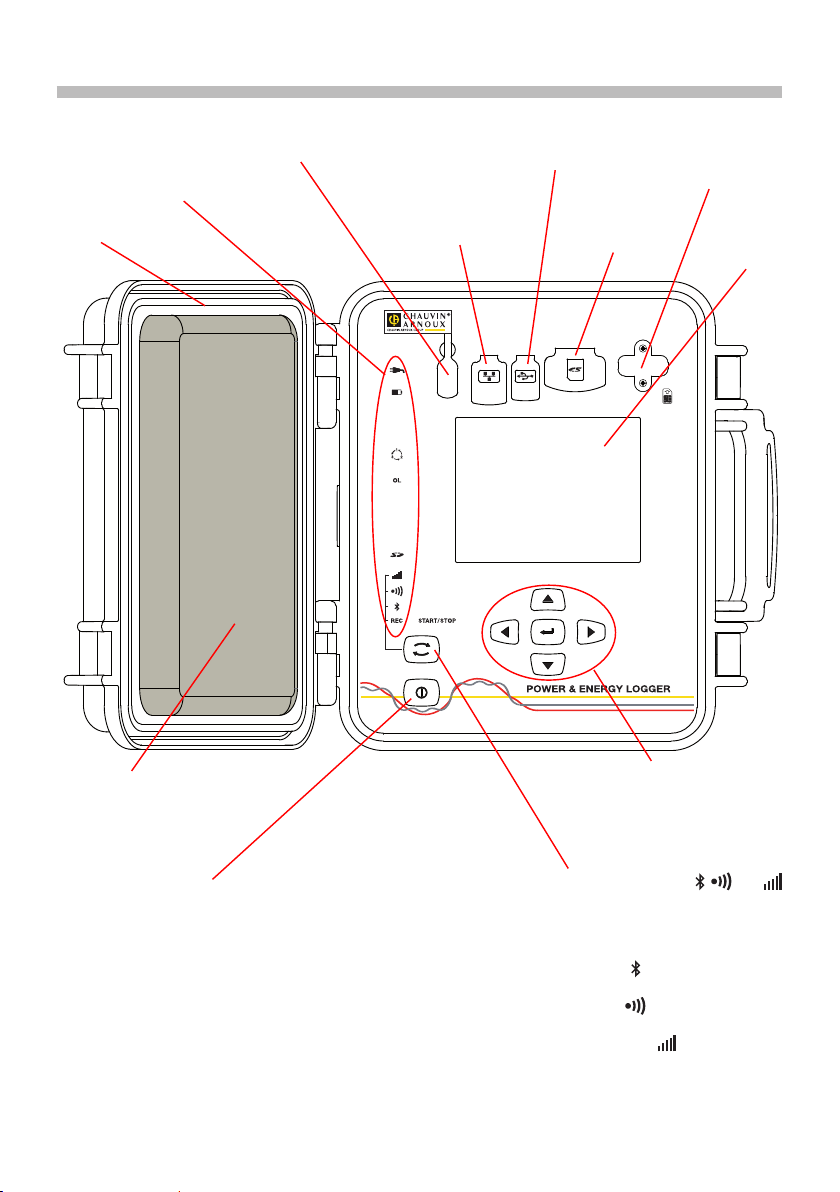
LANCEMENT D’UN ENREGISTREMENT (MARCHE / ARRÊT)
Pour lancer un enregistrement, procédez de l’une des manières suivantes :
Dans PEL Transfer : Sélectionnez l’option appropriée dans l’onglet Enregistrement de la boîte de dialogue
Conguration. L’appareil peut être conguré pour déclencher un enregistrement soit à une date et une heure future,
soit immédiatement après la n de la conguration sur l’appareil.
Sur l’appareil : Appuyez sur le bouton Sélection et maintenez-le appuyé jusqu’à ce que le voyant REC s’allume,
puis relâchez-le. L’appareil démarre l’enregistrement selon les réglages de la conguration précédente.
Pour arrêter un enregistrement, procédez de l’une des manières suivantes :
Dans PEL Transfer : Dans le menu, sélectionnez Appareil > Arrêter l’enregistrement .
Sur l’appareil : Appuyez sur le bouton Sélection et maintenez-le enfoncé jusqu’à ce que le voyant REC s’allume,
puis relâchez-le.
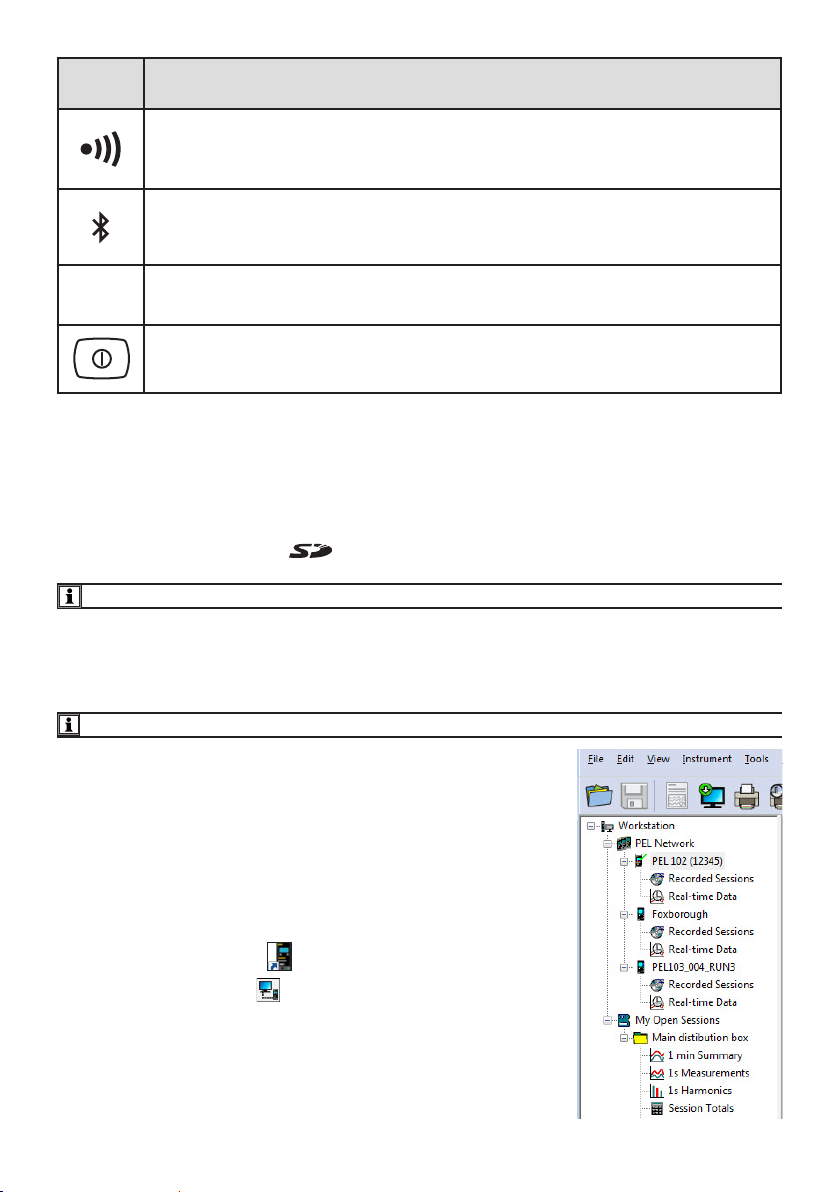
AFFICHAGE DE L’ENREGISTREMENT
Les données enregistrées peuvent être transférées de deux manières sur le PC pour y être achées et pour générer
des rapports :
La carte SD peut être retirée de l’appareil et branchée sur le PC via le lecteur de carte SD fourni. Lancez PEL
Transfer, sélectionnez la commande Ouvrir dans le menu Fichier, pointez le chier ICP portant le numéro de
session souhaité sur la carte SD et sélectionnez Ouvrir.
Connexion directe entre le PC et le PEL (USB, Ethernet, Wi-Fi ou Bluetooth). Lancez PEL Transfer, ouvrez une
connexion vers l’appareil, sélectionnez-le (veillez à ce qu’il soit connecté) dans l’arborescence, puis sélectionnez
Sessions enregistrées. Double-cliquez sur la session d’enregistrement souhaitée. Une fois le téléchargement
terminé, sélectionnez le test téléchargé et cliquez sur le bouton Ouvrir dans la boîte de dialogue Téléchargement.
Dans les deux cas, la session s’ajoute à Mes sessions ouvertes dans l’arborescence. Les données peuvent alors
être achées.
NOTICE DE FONCTIONNEMENT
Rendez-vous sur notre site Internet pour télécharger la notice de fonctionnement de votre appareil :
www.chauvin-arnoux.com
Eectuez une recherche avec le nom de votre appareil. Une fois l’appareil trouvé, allez sur sa page. La notice de
fonctionnement se trouve sur la droite. Téléchargez-la.

QUICK START GUIDE TO THE PEL 106 (EN)
PEL 106
POWER & ENERGY LOGGER
9 indicators providing
status information.
Connector for external power supply
(optional mains power unit).
RJ45 Ethernet
connector.
USB connector.
Slot for SD card.
SIM card slot.
Directional keypad: four navigation
keys and one validation key
(Enter key).
Selection key.
Press the key and hold it down. The REC, , and
indicators light one by one, for 3 seconds each.
Release the key while the desired function is lit.
If you release it while the REC indicator is lit,
recording starts or stops.
If you release it while the indicator is lit, Wi-Fi is
activated or de-activated.
If you release it while the indicator is lit, Wi-Fi is
activated or de-activated.
If you release it while the indicator is lit,
3G-UMTS/GPRS is activated or de-activated.
Start/Stop key.
To put the instrument into operation, connect the
terminals to mains.
To stop the instrument, disconnect the terminals and
press the button for several seconds.
You cannot switch the PEL o while it is connected to
a power source or while recording is in progress (or
pending).
Bag to stow the waterproof
plugs of the terminals.
QR code.
LCD display
unit.
Installing the SIM card
This is necessary for the 3G-UMTS/GPRS
Unscrew both screws of the SIM card slot and remove
the cover. Insert the SIM card in the direction indicated.
Put the cover back on and screw both screws back in.

INSTALLATION OF THE COLOUR-CODED IDENTIFIERS
For polyphase measurements, mark the current sensors, the voltage leads, and the terminals using the coloured rings
and inserts provided with the instrument, assigning one colour to each terminal.
Detach the appropriate inserts and place them in the holes above the terminals (the large ones for the current
terminals, the small ones for the voltage terminals).
Clip a ring of the same colour onto each end of the lead that will be connected to the terminal.
VN V3 V2 V1 VE/GND
IN I3 I2 I1
INDICATORS
Indicators Colour and function
Green indicator: Mains
Indicator lit: the instrument is connected to mains by the external power supply (optional mains power unit).
Indicator o: the instrument is powered by the battery or by the voltage inputs.
Orange/red indicator: Battery
When the instrument is connected to mains, the battery is charged.
Indicator o: battery fully charged.
Indicator blinking orange: battery charging.
Indicator blinking red twice a second: battery low (and no mains power).
Red indicator: Phase order
Indicator o: phase order OK.
Indicator blinking once a second: phase order incorrect.
OL
Red indicator: Overshoot of the measurement range
Indicator o: no overshoot on the inputs.
Indicator blinking once a second: at least one input is outside range limits.
Indicator lit: a lead is missing or is connected to the wrong terminal.
Red/green indicator: SD card
Indicator lit green: the SD card is OK.
Indicator lit red: SD card missing or locked.
Indicator blinking red: SD card being reset.
Indicator blinking alternately red and green: SD card full.
Indicator blinking red once every 5s: the SD card will be full before the recording in progress ends.
Green indicator: 3G-UMTS/GPRS
LED o: 3G-UMTS/GPRS link o (disabled)
LED on: 3G-UMTS/GPRS link enabled but not transmitting
LED blinking twice a second: 3G-UMTS/GPRS link enabled and transmitting

Indicators Colour and function
Green indicator: Wi-Fi
Indicator o: Wi-Fi is not activated.
Indicator lit: Wi-Fi is activated but not sending.
Indicator blinking: transmission by Wi-Fi in progress.
Blue indicator: Bluetooth
Indicator o: Bluetooth link de-activated.
Indicator lit: Bluetooth link activated but not transmitting.
Indicator blinking: Bluetooth link activated and transmitting.
REC Green indicator: Recording
Indicator blinking once every 5s: recorder on standby.
Indicator blinking twice every 5s: recorder in record mode.
Green/orange indicator: Start/Stop
Indicator lit green: The instrument is on and is powered by the voltage inputs.
Indicator blinking orange: Supply by the voltage inputs is de-activated.
SD MEMORY CARD
The PEL accepts SD and SDHC cards, FAT32 formatted, up to a capacity of 32 GB.
The PEL is delivered with a formatted SD card. If you want to install another SD card:
Check that the new SD card is not locked.
Format the SD card using PEL Transfer (recommended) or using a PC.
Open the elastomer cap marked .
Press on the SD card in the instrument and withdraw it.
Warning: do not withdraw the SD card if recording is in progress.
Insert the new card and push it home.
Put the elastomer cap back on to keep the instrument waterproof.
INSTALLING PEL TRANSFER®
Do not connect the instrument to the PC until you have installed the software and the driver.
Insert the CD in your CD-ROM drive.
Go to the PEL_Transfer_software directory and run setup.exe.
Then follow the installation instructions.
Remark: For complete installation instructions, refer to the manual on the CD-ROM.
OPENING PEL TRANSFER
Connect the voltage inputs of the PEL to mains. The instrument is turned on.
Connect the PEL to the PC using the USB cable provided. Wait until the driver
is fully installed before continuing.
Double-click on the PEL icon on the desktop to open PEL Transfer.
Select the Add instrument icon in the toolbar or in the main Instrument
menu.
Follow the instructions of the Add an instrument wizard. If PEL Transfer does
not detect the instrument in the pull-down list, click on the Update button.
When the connection with the instrument is established, the name of the
instrument should appear on the side left of the window in the PEL Network
branch of the tree.
Example of PEL Network directory

12-2019
695834A02 - Ed. 1
CONFIGURING THE INSTRUMENT
To congure your PEL, select the instrument in the PEL Network directory.
Open the Configure the instrument dialogue box by clicking on the Configure icon in the toolbar, in the Instrument
menu, or in the Status zone.
This dialogue box has several tabs:
General: Contains elds used to assign a name to the instrument, along with auto-o command, LCD display unit
command, operating button, clock setting, and SD card formatting options.
Communication: Options concerning the Bluetooth link, Wi-Fi, the Ethernet network and the 3G-UMTS/GPRS.
Measurement: Selection of the distribution system, voltage ratio, and frequency.
Current sensor: Detection of the current sensors and choice of the nominal primary current.
Recording: Recording parameter options.
Meters: Reset of the meters and partial energy meter reset options.
Alarms: programming of the alarms.
Nominal values: dene the nominal values .
L452: connect the Data Logger to the instrument.
Report: congure reports and send them by email
Click on OK to transfer the new conguration to the instrument.
STARTING RECORDING (START/STOP)
To start recording, do one of the following:
In PEL Transfer: Select the appropriate option in the Recording tab of the Conguration dialogue box. The
instrument can be congured to start recording either at some future date and time, or immediately after recording
is congured on the instrument.
On the instrument: Press the Selection button and hold it down until the REC indicator lights, then release it. The
instrument starts recording as it was previously congured to do.
To stop recording, do one of the following:
In PEL Transfer: In the menu, select Instrument > Stop recording .
On the instrument: Press the Selection button and hold it down until the REC indicator lights, then release it.
VIEWING THE RECORDING
The recorded data can be transferred to the PC in two ways and then be displayed there and used to create reports:
The SD card can be withdrawn from the instrument and connected to the PC using the SD card reader provided.
Start PEL Transfer, select the Open command in the File menu, point to the ICP le bearing the desired session
number on the SD card, and select Open.
Direct connection between the PC and the PEL (USB, Ethernet, Wi-Fi, or Bluetooth). Start PEL Transfer, open a
connection to the instrument, select the instrument (make sure that it is connected) in the tree, then select Recorded
sessions. Double-click on the desired recorded session.When the download is over, select the downloaded test
and click on the Open button in the Download dialogue box.
In both cases, the session is added to My open sessions in the tree. The data can then be displayed.
USER’S MANUAL
Visit our web site to download the operating instructions for your instrument:
www.chauvin-arnoux.com
Search on the name of your instrument. When you have found the instrument, go to its page. The operating instructions
are on the right. Download them.

SCHNELLSTART-ANLEITUNG PEL106 (DE)
PEL 106
POWER & ENERGY LOGGER
9 Signallampen
als Statusanzeigen.
Anschluss für Spezial-Netzteil,
Netzadapter (Option)
Ethernet-Stecker RJ45.
USB-Anschluss.
SD-Kartenschlitz.
SIM-Kartenschlitz.
Pfeilfeld: vier Pfeiltasten
und eine Bestätigungstaste
(Eingabe).
Taste Auswahl.
Drücken Sie die Taste und halten Sie sie. Die Signallampen
REC, , und leuchten hintereinander je 3 Sek.
lang.
Lassen Sie die Taste los, während die Signallampe der
gewünschten Funktion leuchtet.
Wenn Sie also loslassen, während REC leuchtet,
dann wird die Aufzeichnung gestartet bzw. gestoppt.
Wenn Sie loslassen, während leuchtet, dann wird
die Bluetooth-Verbindung aktiviert bzw. deaktiviert.
Wenn Sie loslassen, während leuchtet, dann
wird WLAN aktiviert bzw. deaktiviert.
Wenn Sie loslassen, während leuchtet, dann wird
3G-UMTS/GPRS aktiviert bzw. deaktiviert.
Taste Ein/Aus.
Zum Einschalten des Geräts schließen Sie die
Buchsen an das Netz an.
Zum Abschalten des Geräts nehmen Sie die
Buchsen ab und drücken Sie den Knopf ein paar
Sekunden lang.
Der PEL kann nicht abgeschaltet werden, solange er an
eine Stromversorgung angeschlossen ist und solange
eine Aufzeichnung läuft bzw. programmiert ist.
Transporttasche
Schutzstöpsel für die
Buchsen.
QR-Code.
LCD-Anzeige.
Einsetzen der SIM-Karte
Diese ist für die 3G-UMTS/GPRS-Verbindung erforderlich.
Die beiden Schrauben vom SIM-Kartenschlitz
abschrauben und die Abdeckung entfernen. Legen
Sie die SIM-Karte in die vorgegebene Richtung ein.
Bringen Sie die Abdeckung wieder an und schrauben
Sie die beiden Schrauben fest.

ANBRINGEN DER FARBKLEMMEN
Bei Mehrphasenmessung zuerst jeden Stromwandler, Prüfdraht und alle Anschlüsse mit Farbringen und Stiften
kennzeichnen (im Lieferumfang inbegrien), wobei jedem einzelnen Anschluss eine Farbe zugeordnet wird.
Dazu die Farbklemmen lösen und in die Löcher über den Buchsen stecken, die Großen in die Stromeingänge, die
Kleinen in die Spannungseingänge.
Dann den gleichfarbigen Ring an die Spitze stecken, die zum betreenden Eingang gehört.
VN V3 V2 V1 VE/GND
IN I3 I2 I1
SIGNALLAMPEN
Signallampen
Farbe und Funktion
Grüne LED: Netz
LED leuchtet: Das Gerät ist über die externe Stromversorgung (Netzadapter (Option)) mit dem
Stromnetz verbunden
LED leuchtet nicht: Das Gerät wird mit Akku oder über die Spannungseingänge betrieben.
Orange/Rote LED: Akku
Der Akku lädt sich wieder ganz auf, wenn das Gerät an das Stromnetz angeschlossen ist.
LED leuchtet nicht: Akku ist geladen.
Orange LED blinkt: Akku wird geladen.
Rote LED blinkt im Sekundentakt zwei Mal: Akku schwach und keine Netzversorgung vorhanden.
Rote LED: Phasenfolge
LED leuchtet nicht: Drehrichtung der Phasen ist richtig.
LED blinkt im Sekundentakt ein Mal: Drehrichtung der Phasen ist falsch.
OL
Rote LED: Messbereichsüberschreitung
LED leuchtet nicht: Kein Overload an den Eingängen.
LED blinkt im Sekundentakt ein Mal: Überlast an zumindest einem Eingang.
LED leuchtet: Eine Leitung fehlt bzw. ist falsch angeschlossen.
Rote/grüne LED: SD-Karte
Grüne LED leuchtet: SD-Karte ist OK.
Rote LED leuchtet: SD-Karte fehlt bzw. ist gesperrt.
Rote LED blinkt: SD-Karte wird initialisiert.
Rote und grüne LED blinken abwechselnd: SD-Karte ist voll.
Rote LED blinkt alle 5 Sek. ein Mal: Die SD-Karte wird vor dem Ende der Aufzeichnung voll sein.
Grüne LED: 3G-UMTS/GPRS
LED leuchtet nicht: 3G-UMTS/GPRS ist nicht aktiviert.
LED leuchtet: 3G-UMTS/GPRS ist aktiviert aber sendet nicht.
LED blinkt im Sekundentakt zwei Mal: 3G-UMTS/GPRS aktiv, Übertragung läuft.

Signallampen
Farbe und Funktion
Grüne LED: WLAN
LED leuchtet nicht: WLAN ist nicht aktiviert.
LED leuchtet: WLAN ist aktiviert aber sendet nicht.
LED blinkt: WLAN-Übertragung läuft.
Blaue LED: Bluetooth
LED leuchtet nicht: Bluetooth ist nicht aktiviert.
LED leuchtet: Bluetooth ist aktiviert aber sendet nicht.
LED blinkt: Bluetooth-Übertragung läuft.
REC Grüne LED: Aufzeichnung
LED blinkt alle 5 Sek. ein Mal: Logger ist in Bereitschaft.
LED blinkt alle 5 Sek. zwei Mal: Logger ist in Aufzeichnungsmodus.
Grün/orange LED: Ein/Aus
Grüne LED leuchtet: Das Gerät läuft und wird über die Spannungseingänge betrieben.
Orange LED blinkt: Versorgung über die Spannungseingänge ist deaktiviert.
SD-SPEICHERKARTE
Der PEL funktioniert mit FAT32-formatierten SDHC-Karten und mit bis zu 32 Gb Kapazität.
PEL wird mit einer formatierten SD-Karte geliefert. Wenn Sie eine neue SD-Karte installieren möchten:
Sicherstellen, dass die neue SD-Karte nicht gesperrt ist.
Die SD-Karte vorzugsweise mit PEL-Transfer oder mit einem PC formatieren.
Elastomerabdeckung önen .
Die SD-Karte in das Gerät drücken und entfernen.
Achtung: SD-Karte nicht herausnehmen solange eine Aufzeichnung läuft.
Neue Karte bis zum Anschlag einschieben.
Elastomerabdeckung wieder anbringen, damit das Gerät dicht bleibt.
PEL TRANSFER®INSTALLIEREN
Das Gerät erst an den pc anschliessen, wenn software und treiber installiert sind!
CD in das CD-ROM-Laufwerk einlegen.
Gehen Sie in das Verzeichnis „PEL_Transfer_software“ und starten Sie
„setup.exe“.
Jetzt folgen Sie den Installationsanweisungen
Hinweis: Eine ausführliche Installationsanweisung finden Sie in der
Bedienungsanleitung auf der CD-Rom.
PEL TRANSFER ÖFFNEN
Die PEL-Spannungseingänge an das Netz anstecken. Das Gerät schaltet sich ein.
PEL mit dem gelieferten USB-Kabel an den PC anschließen. Abwarten, bis
die Treiber fertig installiert.
Das PEL-Symbol auf dem Desktop doppelt anklicken, PEL Transfer
wird geönet.
In der Symbolleiste das Symbol Neues Gerät wählen bzw. im Hauptmenü Gerät.
Anweisungen des Assistenten Neues Gerät befolgen. Wenn PEL Transfer das
Gerät nicht in der Drop-Down-Liste anzeigt, klicken Sie auf Erneut abfragen.
Sobald die Verbindung mit dem Gerät aufgebaut ist, sollte es links neben dem
PEL Transfer im PEL Netzwerk Baumdiagramm erscheinen. Beispiel für ein PEL-Netz-Verzeichnis

12-2019
695834A03 - Ed. 1
GERÄTEKONFIGURATION
Das Gerät im PEL-Netzwerk wählen, um die Konguration durchzuführen.
In der Symbolleiste das Symbol Konfigurieren anklicken und das Dialogfeld Gerätekonfiguration önen bzw. im
Hauptmenü Gerät oder im Status-Bereich.
In diesem Dialogfeld gibt es mehrere Registerkarten:
Allgemeines: Gerätebezeichnungen eingeben, Optionen für Abschaltautomatik, LCD-Steuerung, Steuertasten,
Geräteuhr und SD-Karten-Formatierung festlegen.
Datenübertragung: Optionen für Bluetooth, WLAN, Ethernet und 3G-UMTS/GPRS festlegen.
Messen: Verteilernetz, Spannungsverhältnis und Frequenz festlegen.
Stromwandler: Stromwandler erfassen und Primärnennstrom auswählen.
Speichern: Optionen für Aufzeichnungswerte festlegen.
Zähler: Die Zähler rücksetzen und Optionen für das Rücksetzen der Teilenergiezähler festlegen.
Alarme: Alarmmeldungen programmieren.
Nennwerte: Die Nennwerte festlegen.
L452: Datenlogger mit dem Gerät verbinden
Bericht: Berichte kongurieren und per E-Mail senden.
Auf OK klicken und die neue Konguration übertragen.
START EINER AUFZEICHNUNG (EIN/AUS)
Es gibt mehrere Möglichkeiten, eine Aufzeichnung zu starten:
In PEL Transfer: Im Dialogfeld Konguration, Registerkarte Aufzeichnung, die entsprechende Option wählen.
Das Gerät kann so konguriert werden, dass die Aufzeichnung entweder zu einem bestimmten späteren Zeitpunkt
startet oder sofort bei Übernahme der neuen Konguration in das Gerät.
Am Gerät: Die Taste Wahl solange gedrückt halten, bis die LED REC aueuchtet, dann loslassen. Das Gerät
startet die Aufzeichnung nach der vorgegebenen Konguration.
Es gibt folgende Möglichkeiten, eine Aufzeichnung zu beenden:
In PEL Transfer: Im Menü unter Gerät > Aufzeichnung .
Am Gerät: Die Taste Wahl solange gedrückt halten, bis die LED REC aueuchtet, dann loslassen.
ANZEIGE DER AUFZEICHNUNGEN
Auf dem PC können die Daten angezeigt und Berichte erstellt werden. Es gibt zwei verschiedene Arten, die Daten auf
den PC herunterzuladen:
Die SD-Karte aus dem Gerät herausnehmen und mit dem gelieferten SD-Karten-Laufwerk an den PC anschließen.
PEL-Transfer aufrufen, im Datei-Menü den Befehl Öffnen wählen. Auf der SD-Karte die ICP-Datei mit der
gewünschten Vorgangsnummer anwählen und Öffnen wählen.
Direkte Verbindung zwischen PC und PEL via USB, Netzwerk oder Bluetooth. PEL-Transfer aufrufen, Verbindung
mit dem Gerät önen -darauf achten, dass sie auch hergestellt wird-, Verbindung im Baumdiagramm auswählen
und dann Aufgezeichnete Vorgänge wählen. Den gewünschten Vorgang doppelt anklicken.Wenn der Ladevorgang
abgeschlossen ist, kann der geladene Test geönet werden. Dazu wählt man ihn im Dialogfeld aus und klickt auf
Öffnen.
In beiden Fällen erscheint der Vorgang unter Eigene aktuelle Vorgänge im Baumdiagramm. Jetzt stehen die Daten
zur Anzeige bereit.
BEDIENUNGSANLEITUNG
Rufen Sie unsere Website auf, wo die Bedienungsanleitung Ihres Geräts zum Herunterladen bereitsteht:
www.chauvin-arnoux.com
Führen Sie mit dem Namen des Geräts als Stichwort eine Suche durch. Gehen Sie dann zur entsprechenden Seite,
die Bedienungsanleitung bendet sich rechter Hand. Nun können Sie sie herunterladen.

GUIDA DI AVVIO RAPIDO DEL PEL106 (IT)
PEL 106
POWER & ENERGY LOGGER
9 spie che forniscono
informazioni di stato.
Connettore per alimentazione
esterna (blocco rete in opzione).
Connettore
Ethernet RJ45.
Connettore USB.
Alloggiamento
della scheda SD.
Alloggiamento
della scheda SIM.
Quattro tasti di navigazione e un
tasto di convalida (tasto Enter).
Tasto Selezione.
Premete il tasto e mantenete la pressione. Le spie
REC, , e si accendono successivamente per
3 secondi ciascuna.
Abbandonate il tasto mentre la funzione voluta è accesa.
Se lo abbandonate mentre la spia REC è accesa,
la registrazione si avvia o si ferma.
Se lo abbandonate mentre la spia è accesa, il
collegamento Bluetooth si attiva o si disattiva.
Se lo abbandonate mentre la spia è accesa, la
Wi-Fi si attiva o si disattiva.
Se lo abbandonate mentre la spia è accesa, la
3G-UMTS/GPRS si attiva o si disattiva.
Tasto Marcia/Arresto.
Per mettere lo strumento in marcia, collegate
i morsetti alla rete.
Per fermare lo strumento, staccate i morsetti
e premete il bottone per vari secondi.
Non potete spegnere il PEL nché è collegato a una
sorgente d’alimentazione o nché una registrazione
è in corso (o in attesa).
Borsa per sistemare i tappi
ermetici dei morsetti.
Codice QR.
Display LCD.
Installazione della scheda SIM
La scheda è necessaria per il collegamento 3G-UMTS/
GPRS
Svitate le 2 viti dell’alloggiamento della scheda SIM e
rimuovete lo sportello. Inserite la scheda SIM rispettando
il senso indicato. Rimettete lo sportello al suo posto e
riavvitate le 2 viti.

INSTALLAZIONE DEI RIFERIMENTI COLORATI
Per le misure polifasi, identicate i sensori di corrente, i cavi di tensione e i morsetti con gli anelli e perni colorati forniti
con lo strumento, attribuendo un colore a ogni morsetto.
Staccate i perni appropriati e inseriteli nei fori al di sopra dei morsetti (i grandi per i morsetti della corrente, i piccoli
per i morsetti di tensione).
Fissate un anello di colore identico a ogni estremità del cavo da collegare al morsetto.
VN V3 V2 V1 VE/GND
IN I3 I2 I1
SPIE
Spie Colore e funzione
Spia verde: Rete
Spia accesa: lo strumento è collegato alla rete mediante l’alimentazione esterna (blocco rete in opzione).
Spia spenta: lo strumento funziona su batteria o grazie agli ingressi tensione.
Spia arancione/rossa: Batteria
Quando lo strumento è collegato alla rete, la batteria è sotto carica.
Spia spenta: batteria piena.
Spia arancione lampeggiante: batteria sotto carica.
Spia rossa lampeggiante due volte al secondo: batteria debole (e assenza d’alimentazione rete).
Spia rossa: Ordine delle fasi
Spia spenta: l’ordine di rotazione delle fasi è corretto.
Spia lampeggiante una volta al secondo: l’ordine di rotazione delle fasi è errato.
OL
Spia rossa: Superamento della portata di misura
Spia spenta: nessun superamento sugli ingressi.
Spia lampeggiante una volta al secondo: almeno un ingresso è in superamento.
Spia accesa: manca un cavo oppure è collegato al morsetto sbagliato.
Spia rossa/verde: Scheda SD
Spia verde accesa: la scheda SD è OK.
Spia rossa accesa: scheda SD assente o bloccata.
Spia rossa lampeggiante: scheda SD in corso d’inizializzazione.
Spia lampeggiante alternativamente rossa e verde: scheda SD satura.
Spia rossa lampeggiante 1 volta ogni 5s: la scheda SD sarà satura prima della ne della
registrazione in corso.
Spia verde: 3G-UMTS/GPRS
Spia spenta: collegamento 3G-UMTS/GPRS fermo (disattivato)
Spia accesa: collegamento 3G-UMTS/GPRS attivato, ma senza trasmissione
Spia lampeggiante due volte al secondo: collegamento 3G-UMTS/GPRS attivato e in corso di
trasmissione.

Spie Colore e funzione
Spia verde: Wi-Fi
Spia spenta: la Wi-Fi non è attivata.
Spia accesa: la Wi-Fi è attivata ma non emette.
Spia lampeggiante: trasmissione mediante Wi-Fi in corso.
Spia blu: Bluetooth
Spia spenta: collegamento Bluetooth disattivato.
Spia accesa: collegamento Bluetooth attivato, ma senza trasmissione.
Spia lampeggiante: collegamento Bluetooth attivato e in corso di trasmissione.
REC Spia verde: Registrazione
Spia lampeggiante una volta ogni 5s: registratore in attesa.
Spia lampeggiante due volte ogni 5s: registratore in modalità registrazione.
Spia verde/arancione: Marcia/Arresto
Spia verde accesa: lo strumento funziona ed è alimentato dagli ingressi tensione.
Spia arancione lampeggiante: L’alimentazione mediante gli ingressi tensione è disattivata.
SCHEDA MEMORIA SD
Il PEL accetta le schede SD e SDHC, formattate in FAT32, no a 32 Go di capacità.
Il PEL è fornito con una scheda SD formattata. Se volete installare una nuova scheda SD:
Vericate che la nuova scheda SD non sia bloccata.
Formattate la scheda SD mediante il PEL Transfer (raccomandato) o mediante un PC.
Aprire il cappuccio di elastomero contrassegnato da .
Premete la scheda SD che è nello strumento e rimuovetela.
Attenzione: non rimuovete la scheda SD se una registrazione è in corso.
Inserite la nuova scheda spingendola a fondo.
Rimettete al suo posto il cappuccio di elastomero per conservare l’ermeticità dello strumento.
INSTALLAZIONE DEL PEL TRANSFER®
Non collegate lo strumento al PC prima di avere installato i software e i driver.
Introducete il CD nel lettore del CD-ROM.
Andate nella directory PEL_Transfer_software e lanciate setup.exe.
Poi seguite le istruzioni d’installazione.
Osservazione: per tutte le istruzioni d’installazione, si rimanda al manuale fornito
sul CD-ROM.
APERTURA DEL PEL TRANSFER
Collegate gli ingressi tensione del PEL alla rete. Lo strumento si mette in
marcia.
Collegate il PEL al PC con il cavo USB fornito. Attendete che i driver abbiano
nito la loro installazione prima di continuare.
Con un doppio clic sull’icona del PEL sul desktop aprirete il PEL Transfer.
Selezionate l’icona Aggiunta Strumento nella barra degli strumenti o nel
menu principale Strumento.
Seguite le istruzioni dell’assistente Aggiunta Strumento. Se il PEL Transfer
non rivela lo strumento nel menu a tendina, cliccate sul bottone Attualizzare.
Quando la connessione con lo strumento è instaurata, il nome di quest’ultimo
deve visualizzarsi sul lato sinistro della nestra nel ramo Rete PEL dell’albero.
Esempio di directory Rete PEL

12-2019
695834A04 - Ed. 1
CONFIGURAZIONE DELLO STRUMENTO
Per congurare il vostro PEL, selezionate lo strumento nella directory Rete PEL.
Aprite la casella di dialogo Configurare lo strumento cliccando sull’icona Configurare nella barra degli strumenti,
nel menu Strumento o nella zona Stato.
Questa casella di dialogo comporta alcuni tab:
Generale: comporta campi che permettono di attribuire un nome allo strumento, opzioni di arresto automatico, di
impostazione del display LCD, di bottoni di funzionamento, di impostazione dell’orologio e di formattazione della
scheda SD.
Comunicazione: opzioni relative alla Wi-Fi, al collegamento Bluetooth, alla rete Ethernet e alla 3G UMTS/GPRS
Misura: selezione del sistema di distribuzione, rapporto delle tensioni e selezione della frequenza.
Sensore di corrente: rivelazione dei sensori di corrente e scelta della corrente nominale primaria.
Registrazione: selezione dei parametri di registrazione.
Contatori: reinizializzazione dei contatori e opzioni di reinizializzazione dei contatori d’energia parziale.
Allarmi: programmazione degli allarmi.
Valori nominali: impostare i valori nominali .
L452 : collegare i Data Logger allo strumento.
Report : congurare i report e inviarli in e-mail
Cliccate su OK per trasferire sullo strumento la nuova congurazione.
LANCIO DI UNA REGISTRAZIONE (MARCIA/ARRESTO)
Per lanciare una registrazione, procedete in una delle maniere sottoindicate:
In PEL Transfer: Selezionate l’opzione appropriata nel tab Registrazione della casella di dialogo Congurazione.
È possibile congurare lo strumento per attivare una registrazione in una determinata data e ora futura oppure
immediatamente dopo la ne della congurazione sullo strumento.
Sullo strumento: Premete il bottone Selezione e mantenetelo premuto no a quando la spia REC si accende,
poi abbandonatelo. Lo strumento avvia la registrazione secondo le regolazioni della congurazione precedente.
Per fermare una registrazione, procedete in una delle maniere sottoindicate:
In PEL Transfer: nel menu, selezionate Strumento > Fermare la registrazione .
Sullo strumento: Premete il bottone Selezione e mantenetelo premuto no a quando la spia REC si accende,
poi abbandonatelo.
VISUALIZZAZIONE DELLA REGISTRAZIONE
È possibile trasferire i dati registrati sul PC per opportuna visualizzazione e edizione di report. Esistono due maniere:
La scheda SD può venire rimossa dallo strumento e collegata al PC mediante il fornito lettore di schede SD. Lanciate
PEL Transfer, selezionate il comando Aprire nel menu File, puntate il le ICP munito del numero di sessione voluto
sulla scheda SD e selezionate Aprire.
Connessione diretta fra il PC e il PEL (USB, Ethernet, Wi-Fi o Bluetooth). Lanciate PEL Transfer, aprite una
connessione verso lo strumento, selezionatelo (vericate che sia collegato) nell’albero, poi selezionate Sessioni
registrate. Eettuate un doppio clic sulla sessione di registrazione voluta. Alla ne del download, selezionate il
test scaricato e cliccate sul bottone Aprire nella casella di dialogo Download.
In entrambi i casi, la sessione si aggiunge a Mie sessioni aperte nell’albero. È possibile allora visualizzare i dati.
MANUALE D’USO
Visitate il nostro sito Internet per scaricare il manuale d’uso del vostro strumento:
www.chauvin-arnoux.com
Eettuare una ricerca con il nome del vostro strumento. Una volta trovato lo strumento andate sulla pagina corrispondente.
Il manuale d’uso si trova sulla destra: scaricatelo

GUÍA DE INICIO RÁPIDO DEL PEL106 (ES)
PEL 106
POWER & ENERGY LOGGER
9 pilotos que proporcionan
información de estado.
Conector para alimentación externa
(adaptador de CA opcional).
Conector
Ethernet RJ45.
Conector USB.
Ranura para
tarjeta SD.
Ranura de la
tarjeta SIM.
Pad direccional: cuatro teclas
de navegación y una tecla de
validación (tecla Entrada).
Tecla Selección.
Pulse la tecla y manténgala pulsada. Los pilotos REC,
, y se encienden sucesivamente durante 3
segundos cada uno.
Suelte la tecla cuando la función deseada está
encendida.
Si la suelta mientras el piloto REC está encendido,
el registro se inicia o detiene.
Si la suelta mientras el piloto está encendido, la
conexión Bluetooth se activa o desactiva. Si la suelta
mientras el piloto está encendido, el Wi-Fi se
activa o desactiva.
Si la suelta mientras el piloto está encendido, la
3G-UMTS/GPRS se activa o desactiva.
Tecla On/Off.
Para encender el instrumento, conecte los bornes
a la red eléctrica.
Para apagar el instrumento, desconecte los bornes
y pulse el botón durante varios segundos.
No puede apagar el PEL mientras siga conectado a una
fuente de alimentación o siga registrando (o en modo
en espera).
Bolsa para guardar los
tapones herméticos de los
bornes.
Código QR.
Display LCD.
Instalación de la tarjeta SIM
Es necesaria para la conexión 3G-UMTS/GPRS
Desatornille los 2 tornillos del compartimiento de la
tarjeta SIM y quite la tapa. Inserte la tarjeta SIM en el
sentido indicado. Vuelva a colocar la tapa y a atornillar
los 2 tornillos.

INSTALACIÓN DE LOS MARCADORES DE COLOR
Para las medidas multifásicas, identique los sensores de corriente, los cables de tensión y los bornes con las anillas
e identicadores de color suministrados con el instrumento, atribuyendo un color a cada borne.
Despegue los identicadores apropiados y colóquelos en los agujeros arriba de los bornes (los grandes para los
bornes de corriente, los pequeños para los bornes de tensión).
Enganche una anilla del mismo color a cada extremo del cable que se conectará al borne.
VN V3 V2 V1 VE/GND
IN I3 I2 I1
PILOTOS
Pilotos Color y función
Piloto verde: Red eléctrica
Piloto encendido: el instrumento está conectado a la red eléctrica con la alimentación externa (adaptador
de CA opcional).
Piloto apagado: el instrumento funciona con la batería o las entradas de tensión.
Piloto naranja/rojo: Batería
Cuando el instrumento está conectado a la red eléctrica, la batería se carga.
Piloto apagado: batería llena.
Piloto naranja parpadeando: batería cargándose.
Piloto rojo parpadeando dos veces por segundo: batería baja (y ausencia de alimentación eléctrica).
Piloto rojo: Orden de las fases
Piloto apagado: orden de rotación de las fases correcto.
Piloto parpadeando una vez por segundo: orden de rotación de las fases incorrecto.
OL
Piloto rojo: Rebasamiento del rango de medida
Piloto apagado: ningún rebasamiento en las entradas.
Piloto parpadeando una vez por segundo: al menos una entrada está en rebasamiento.
Piloto encendido: falta un cable o no está conectado al borne adecuado.
Piloto rojo/verde: Tarjeta SD
Piloto verde encendido: la tarjeta SD está bien.
Piloto rojo encendido: tarjeta SD ausente o bloqueada.
Piloto rojo parpadeando: tarjeta SD inicializándose.
Piloto que parpadea de forma alterna en rojo y verde: tarjeta SD llena.
Piloto rojo parpadeando 1 vez cada 5 s: la tarjeta SD estará llena antes de que acabe el registro.
Piloto verde: 3G-UMTS/GPRS
Piloto apagado: conexión 3G-UMTS/GPRS detenida (desactivada)
Piloto encendido: conexión 3G-UMTS/GPRS activada, pero sin transmisión
Piloto parpadeando dos veces cada segundo: conexión 3G-UMTS/GPRS activada y transmitiendo

Pilotos Color y función
Piloto verde: Wi-Fi
Piloto apagado: el Wi-Fi no está activado.
Piloto encendido: el Wi-Fi está activado pero no emite.
Piloto parpadeando: transmitiendo mediante Wi-Fi.
Piloto azul: Bluetooth
Piloto apagado: conexión Bluetooth desactivada.
Piloto encendido: conexión Bluetooth activada, pero sin transmisión.
Piloto parpadeando: conexión Bluetooth activada y transmitiendo.
REC Piloto verde: Registro
Piloto parpadeando una vez cada 5 s: registrador en modo en espera.
Piloto parpadeando dos veces cada 5 s: registrador en modo registro.
Piloto verde/naranja: On/O
Piloto verde encendido: el instrumento funciona y está alimentado por las entradas de tensión.
Piloto naranja parpadeando: la alimentación mediante las entradas de tensión está desactivada.
TARJETA DE MEMORIA SD
El PEL acepta tarjetas SD y SDHC, formateadas en FAT32, hasta 32 GB de capacidad.
El PEL se suministra con una tarjeta SD formateada. Si desea instalar una nueva tarjeta SD:
Compruebe que la nueva tarjeta SD no está bloqueada.
Formatee la tarjeta SD con el PEL Transfer (recomendado) o con un PC.
Quite el tapón de elastómero marcado .
Presione la tarjeta SD que se encuentra en el instrumento y sáquela.
Atención: no quite la tarjeta SD si se está registrando.
Inserte la nueva tarjeta y empújela hasta el tope.
Vuelva a colocar el tapón de elastómero para conservar la hermeticidad del instrumento.
INSTALACIÓN DE PEL TRANSFER®
No conecte el instrumento al PC antes de haber instalado los softwares y los controladores de dispositivo.
Introduzca el CD en su lector de CD-ROM.
Entre en el directorio PEL_Transfer_software e inicie setup.exe.
A continuación, siga las instrucciones de instalación..
Observación: para ver las instrucciones de instalación completas, remítase al
manual suministrado en CD-ROM.
ABRIR PEL TRANSFER
Conecte las entradas de tensión del PEL a la red eléctrica. El instrumento
se enciende.
Conecte el PEL al PC con el cable USB suministrado. Espere que los
controladores de dispositivo hayan terminado de instalarse antes de proseguir.
Haga doble clic en el icono del PEL en el escritorio para abrir PEL Transfer.
Seleccione el icono Agregar instrumento en la barra de herramientas
o en el menú principal Instrumento.
Siga las instrucciones del asistente Agregar un instrumento. Si PEL
Transfer no detecta el instrumento en la lista desplegable, haga clic en el
botón Actualizar.
Cuando se haya establecido la conexión con el instrumento, el nombre de
éste debe aparecer en la parte izquierda de la ventana en la rama Red PEL
del árbol. Ejemplo de directorio Red PEL

12-2019
695834A05 - Ed. 1
CONFIGURACIÓN DEL INSTRUMENTO
Para congurar su PEL, seleccione el instrumento en el directorio Red PEL.
Abra el cuadro de diálogo Configurar el instrumento haciendo clic en el icono Configurar en la barra de
herramientas, en el menú Instrumento o en la zona Estado.
Este cuadro de diálogo consta de varias pestañas:
General: contiene campos que permiten asignar un nombre al instrumento, opciones de auto apagado, de ajuste
del display LCD, de funcionamiento de los botones, de conguración del reloj y de formateo de la tarjeta SD.
Comunicación: opciones relativas a la conexión Bluetooth, al Wi-Fi, a la red Ethernet y a la 3G-UMTS/GPRS.
Medida: selección del sistema de distribución, informe de las tensiones y selección de la frecuencia
Sensor de Corriente: detección de los sensores de corriente y selección de la corriente nominal primaria.
Registro: selección de los parámetros de registro.
Contadores: reinicialización de los contadores y opciones de reinicialización de los contadores de energía parcial.
Alarmas: programación de alarmas.
Valores nominales: denir valores nominales.
L452: conectar los Data Logger al instrumento.
Informe: congurar los informes y mandarlos por e-mail
Haga clic en Aceptar para transferir la nueva conguración al instrumento.
INICIO DE UN REGISTRO (ON/OFF)
Para iniciar un registro, realice una de las siguientes acciones:
En PEL Transfer: Seleccione la opción apropiada en la pestaña Registro del cuadro de diálogo Conguración.
El instrumento puede congurarse para iniciar un registro o bien a una fecha y hora futura, o bien inmediatamente
después de terminar la conguración del instrumento.
En el instrumento: Pulse el botón Selección y manténgalo pulsado hasta que el piloto REC se encienda, luego
suéltelo. El instrumento inicia el registro según los ajustes de la conguración anterior.
Para detener un registro, realice una de las siguientes acciones:
En PEL Transfer: en el menú, seleccione Instrumento > Detener el registro .
En el instrumento: pulse el botón Selección y manténgalo pulsado hasta que el piloto REC se encienda, luego
suéltelo.
VISUALIZACIÓN DEL REGISTRO
Los datos registrados pueden transferirse de dos maneras al PC para visualizarlos y generar informes:
La tarjeta SD se puede sacar del instrumento e insertar en el PC en el lector de tarjeta SD suministrado. Inicie
PEL Transfer, seleccione el comando Abrir en el menú Archivo, haga clic derecho en el archivo ICP que lleva el
número de sesión deseado en la tarjeta SD y seleccione Abrir.
Conexión directa entre el PC y el PEL (USB, Ethernet, Wi-Fi o Bluetooth). Inicie PEL Transfer, abra una conexión
con el instrumento, selecciónelo (compruebe que está conectado) en el árbol, y luego seleccione Sesiones
guardadas. Haga doble clic en la sesión de registro deseada. Una vez nalizada la descarga, seleccione la prueba
descargada y haga clic en el botón Abrir en el cuadro de diálogo Descarga.
En ambos casos, la sesión se agrega a Mis sesiones abiertas en el árbol. Se pueden visualizar entonces los datos.
MANUAL DE INSTRUCCIONES
Visite nuestro sitio web para descargar el manual de instrucciones de su instrumento:
www.chauvin-arnoux.com
Realice una búsqueda con el nombre de su instrumento. Una vez encontrado el instrumento, vaya a su página. El
manual de instrucciones se encuentra a la derecha. Descárguelo.
Other manuals for PEL 106
1
Table of contents
Languages:
Other Chauvin Arnoux Data Logger manuals

Chauvin Arnoux
Chauvin Arnoux PEL 51 User manual

Chauvin Arnoux
Chauvin Arnoux C.A 10101 User manual

Chauvin Arnoux
Chauvin Arnoux L452 User manual

Chauvin Arnoux
Chauvin Arnoux pel 102 User manual

Chauvin Arnoux
Chauvin Arnoux PEL 51 User manual

Chauvin Arnoux
Chauvin Arnoux pel 102 User manual

Chauvin Arnoux
Chauvin Arnoux PEL 52 User manual

Chauvin Arnoux
Chauvin Arnoux AEMC DL913 User manual

Chauvin Arnoux
Chauvin Arnoux AEMC DL913 User manual