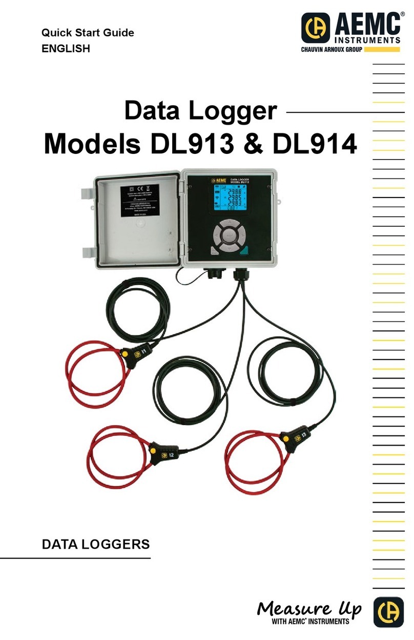
Chauvin Arnoux AEMC DL913 User manual

Data Logger
Models DL913 & DL914
User Manual
ENGLISH
DATA LOGGERS
WITH AEMC
®
INSTRUMENTS

Copyright © Chauvin Arnoux®, Inc. d.b.a. AEMC®Instruments. All rights reserved.
No part of this documentation may be reproduced in any form or by any means (including electronic
storage and retrieval or translation into any other language) without prior agreement and written consent
from Chauvin Arnoux®, Inc., as governed by United States and International copyright laws.
Chauvin Arnoux®, Inc. d.b.a. AEMC®Instruments
15 Faraday Drive • Dover, NH 03820 USA
Tel: (800) 945-2362 or (603) 749-6434 • Fax: (603) 742-2346
This documentation is provided “as is,” without warranty of any kind, express, implied, or otherwise.
Chauvin Arnoux®
but does not warrant the accuracy or completeness of the text, graphics, or other information contained
in this documentation. Chauvin Arnoux®, Inc. shall not be liable for any damages, special, indirect,
user of the documentation has been advised of the possibility of such damages.

Statement of Compliance
Chauvin Arnoux®, Inc. d.b.a. AEMC® Instruments
using standards and instruments traceable to
international standards.
We guarantee that at the time of shipping your
An NIST traceable certicate may be requested
at the time of purchase, or obtained by returning
the instrument to our repair and calibration
facility, for a nominal charge.
The recommended calibration interval for this
instrument is 12 months and begins on the date of
receipt by the customer. For recalibration, please
use our calibration services. Refer to our repair and
calibration section at www.aemc.com.
Serial #:
Catalog #: 2153.61 / 2153.62
Model #: DL913 / DL914
ll in the appropriate date as indicated:
Date Received:
Date Calibration Due:
Chauvin Arnoux®, Inc.
d.b.a AEMC®Instruments
www.aemc.com

TABLE OF CONTENTS
1. INTRODUCTION ................................................................................ 6
1.1 PRECAUTIONS FOR USE ....................................................... 7
1.2 RECEIVING YOUR SHIPMENT................................................ 8
1.3 ORDERING INFORMATION..................................................... 8
1.3.1 Accessories and Replacement Parts............................................. 8
2. PRODUCT FEATURES ..................................................................... 9
2.1 DESCRIPTION ........................................................................... 9
2.2 CONTROL FEATURES ........................................................... 10
2.2.1 Front Panel Interface ................................................................... 10
2.2.2 LCD Display................................................................................. 11
3. SETUP ............................................................................................... 13
3.1 BATTERY CHARGING ............................................................ 13
3.2 CONFIGURATION................................................................... 14
3.2.1 Time/Date Setting ........................................................................ 14
3.2.2 Enabling/Disabling The Wi-Fi...................................................... 15
3.2.3 Measurement Settings ................................................................ 16
3.2.3.1 Current Range .......................................................................... 16
3.2.3.2 Aggregation Period................................................................... 16
3.2.3.3 Recording Mode ....................................................................... 17
3.3 ERASING MEMORY ............................................................... 18
4. OPERATION ..................................................................................... 19
4.1 REAL-TIME MEASUREMENTS .............................................. 19
4.1.1 M A X M od e .................................................................................... 20
4.2 INSTRUMENT SETTINGS (INFORMATION MODE) ........... 20
4.3 RECORDING DATA ................................................................. 22
5. DATAVIEW® ...................................................................................... 23
5.1 INSTALLING DATAVIEW ......................................................... 23
5.2 TYPES OF CONNECTIONS................................................... 24
5.2.1 USB Connection .......................................................................... 24
5.2.2 Wi-Fi via Router........................................................................... 25
5.2.3 Wi-Fi Direct.................................................................................. 26
5.3 REMOTE USER INTERFACE ................................................. 27
6. SPECIFICATIONS ............................................................................ 29
6.1 ELECTRICAL............................................................................ 29
6.2 MECHANICAL.......................................................................... 30
6.3 ENVIRONMENTAL .................................................................. 30
6.4 SAFETY & ELECTROMAGNETIC COMPATIBILITY............ 30
7. MAINTENANCE ................................................................................ 31
7.1 CLEANING ................................................................................ 31
7.2 REPAIR AND CALIBRATION.................................................. 31
7.3 TECHNICAL ASSISTANCE..................................................... 32
7.4 LIMITED WARRANTY ............................................................. 32
7.4.1 Warranty Repairs ......................................................................... 33

6 Data Logger Model DL913 & DL914
1. INTRODUCTION
Thank you for purchasing an AEMC®Instruments Data Logger Model DL913 or
DL914.
For the best results from your instrument and for your safety, you must read the
enclosed operating instructions carefully and comply with the precautions for
CAUTION - Risk of Danger! Indicates a WARNING. Whenever this symbol is
present, the operator must refer to the user manual before operation
Indicates a risk of electric shock. The voltage at the parts marked with this
symbol may be dangerous
Refers to a type B current sensor. Application or withdrawal not authorized on
conductors carrying dangerous voltages. Type B current sensor as per
IEC 61010-2-032
Important information to acknowledge
USB socket
This product complies with the Low Voltage & Electromagnetic Compatibility
European directives (73/23/CEE & 89/336/CEE)
In the European Union, this product is subject to a separate collection system
for recycling electrical and electronic components in accordance with directive
WEEE 2002/96/EC
Denition of Measurement Categories (CAT)
CAT IV corresponds to measurements performed at the primary electrical
supply (<1000 V).
Example: primary overcurrent protection devices, ripple control units, and meters.
CAT III corresponds to measurements performed in the building installation at
the distribution level.
Example: hardwired equipment in xed installation and circuit breakers.
CAT II corresponds to measurements performed on circuits directly connected
to the electrical distribution system.
Example: measurements on household appliances and portable tools.

Data Logger Model DL913 & DL914 7
1.1 PRECAUTIONS FOR USE
For personal safety and for the safety of the environment of use, you must read
and comply with the precautions for use. If you do not comply with these safety
the protection that they provide could be compromised and endanger you.
These instruments comply with safety standard IEC 61010-2-032 for voltages
and categories of installation at an altitude below 6500 ft (2000 m).
gases or fumes
Do not use the instrument if it appears to be damaged, incomplete, or
improperly closed
Before each use, check the condition of the insulation for the cables, case,
and accessories—anything that appears damaged (even partially) must be
reported for repair or scrapping
Observe the environmental conditions of use (§ 6.3)
Do not modify the instrument and use only original replacement parts.
Repairs or adjustments must be performed by authorized personnel
Use protective equipment when required
Do not apply or remove the sensors from hazardous live parts or systems
If hazardous voltages are present at the location of measurement, use
suitable personal protective equipment

8 Data Logger Model DL913 & DL914
1.2 RECEIVING YOUR SHIPMENT
Upon receiving your shipment, make sure that the contents are consistent with
the packing list. Notify your distributor of any missing items. If the equipment
distributor at once with a detailed description of any damage. Save the damaged
packing container to substantiate your claim.
1.3 ORDERING INFORMATION
Data Logger Model DL913............................................................. Cat. #2153.61
(3-Channel)
Includes small classic tool bag, 10 ft USB A to B cable, USB power adapter,
quick start guide, and USB thumb drive with DataView® software and user
manual.
Data Logger Model DL914............................................................. Cat. #2153.62
(4-Channel)
Includes small classic tool bag, 10 ft USB A to B cable, USB power adapter,
quick start guide, and USB thumb drive with DataView software and user manual.
1.3.1 Accessories and Replacement Parts
Bag - Small Classic Tool Bag........................................................... Cat. #2133.72
Cable - 10 ft USB Cable...................................................................Cat. #2136.80
Cable - 6 ft USB Type A to Type B (Waterproof)
for Models DL913 and DL914 .......................................................... Cat. #2153.79
Battery - Rechargeable Battery Pack, 4.3 A·h NiMH
for Models DL913 and DL914 .......................................................... Cat. #2153.80
Replacement 5 V, 2 A USB power adapters are commercially available.
Order Accessories and Replacement Parts Directly Online
Check our Storefront at www.aemc.com/store for availability

Data Logger Model DL913 & DL914 9
2. PRODUCT FEATURES
2.1 DESCRIPTION
The Models DL913 and DL914 are easy-to-use, rugged data loggers that can
be used both indoors and outdoors. Recorded data is stored in the instrument’s
internal memory. This data can then be downloaded to a computer using a
Wi-Fi or USB connection. Then, the data can be analyzed using the Data
Logger Control Panel.
Features include:
■Three (DL913) or four (DL914) 24 inch captive MiniFlex®probes
■Waterproof (IP 67)
■USB for communication and battery charging
■Wi-Fi wireless communication
■1000 V CAT III, 600 V CAT IV
The DL913 and DL914 are powered by two rechargeable NiMH batteries and
can also be externally powered through a USB connection. AEMC®Instruments
recommends using the supplied adapter or a 3.0 USB port for battery charging.

10 Data Logger Model DL913 & DL914
2.2 CONTROL FEATURES
2.2.1 Front Panel Interface
1. LCD display is the instrument interface for displaying measurement data,
as memory, power, and communication status (see § 3.2.2).
2. Navigation buttons
3. Power button turns the instrument ON and OFF with a long press
4. Control button starts and stops recordings (see § 4.3) and selects and
enables the Wi-Fi communication type (see § 3.2.2).
5. Enter button cycles through the displayed data and options.

Data Logger Model DL913 & DL914 11
2.2.2 LCD Display
The LCD is the primary interface for the user to interact with the instrument. The
LCD turns ON when is press
USB port with enough power to charge the instrument. To conserve power, the
LCD backlight will turn OFF after 5 minutes of no button activity. Pressing any
button turns the backlight ON again. The LCD and the control buttons (§ 2.2.1)
provide the features and functionality for the instrument to operate as a
standalone device.
1. Mode indicators
Measurement mode (§ 4.1)
MAX mode (§ 4.1.1)
Information mode (§ 4.2)
2. Display for data and messages
3. Power
ON: Instrument is running on external USB power.
Blinking: Instrument is running on external USB power and communicating
via USB.
OFF: Instrument is running on internal (battery) power.
4. Permanent mode
ON: Permanent mode is enabled, so the instrument will not automatically
power down.
OFF: Permanent mode is disabled, so the instrument will automatically
Control Panel.
5. Wi-Fi Direct
ON (steady): Wi-Fi Direct is enabled and not transmitting.
Blinking: Wi-Fi Direct is actively transmitting.
OFF: Wi-Fi Direct is disabled.
1
2
10
9
8
7
4
5
6
3

12 Data Logger Model DL913 & DL914
6. Wi-Fi (router connection )
ON (steady): Wi-Fi connection is enabled and not transmitting.
Blinking: Wi-Fi is actively transmitting.
OFF: Normal Wi-Fi connection is disabled.
7. Overload
ON: At least one input is out of range and cannot be displayed.
OFF: All inputs are within range.
8. Recording
ON (steady): A recording is in progress.
Blinking: A recording is pending.
Blinking (slowly): A recording is in progress in extended recording mode.
OFF: A recording is neither scheduled nor in progress.
9. Memory
Empty :Instrument memory is empty.
Partially lled :Instrument memory is partially full.
Filled :Instrument memory is full. No recordings can be stored while
the memory is full. Please reference § 3.3 for instructions to erase memory
through the Control Panel.
10. Battery
Empty :The battery must be charged.
Partially lled :The battery is partially charged.
Filled :The battery is fully charged.
Blinking: The battery is charging.

Data Logger Model DL913 & DL914 13
3. SETUP
3.1 BATTERY CHARGING
The instrument is powered via external USB connection or internal rechargeable
batteries. To ensure that recordings continue to completion when external power
is interrupted, we recommend fully charging the batteries before operating the
instrument as explained below.
1. With the instrument disconnected from USB power, press to turn the
instrument ON.
If it does not turn ON, the batteries are depleted and must be charged.
Use the provided USB cable to connect the instrument to an external power
source. The instrument will immediately turn ON.
If the batteries are depleted, skip step 2 below and continue with step 3.
2. Check the battery indicator.
If the indicator is full ( ), the battery is fully charged. You can skip the
remainder of this procedure.
If the indicator is partially full ( ), connect the instrument to an external
power source via the USB cable.
3. While the instrument is running on external power, the battery will charge.
The battery indicator will blink to indicate that the battery is charging. If
depleted, the battery will fully charge in approximately 10 hours without
Wi-Fi enabled. If WiFi is enabled then charge time will be doubled to 20 hours.
4.
select Information mode .
5.
This screen displays the following parameters:
1. Charging current
2. Charging voltage
3. Battery voltage
6. When the battery is fully charged, the battery indicator will stop blinking and
1
2
3

14 Data Logger Model DL913 & DL914
3.2 CONFIGURATION
The Data Logger Control Panel is the primary interface for setting up and
operating the Models DL913 and DL914.
Setup tasks include the following:
■Connecting the instrument to the computer
■Setting the instrument date and time
■Selecting parameters, like the aggregation period and communication options
■Scheduling, starting, and stopping recordings
■Transferring recorded data from the instrument to the computer
■Erasing the instrument’s memory
Data Logger Control Panel software. See § 5 for instructions on installing the
Data Logger Control Panel.
front panel interface. These include the following:
■Enabling Wi-Fi (via direct connection or router)
■Selecting the nominal current and the number of sensor wraps (turns)
■Selecting the aggregation period
■Selecting the recording mode
■Erasing instrument memory
icon is highlighted. There are two situations that prevent you from making
■
■A recording session is in progress or scheduled
LOCKED will appear on the LCD display when you select the icon.
3.2.1 Time/Date Setting
Before recording data, the instrument’s time and date must be accurate. The
time and date can be set via the DataView®Data Logger Control Panel (consult
the Control Panel Help for instructions). To check the instrument date and time,
use the following instructions:
1. In Information mode
Date and Time screens.
2. If the correct date or time is not displayed, connect the instrument to a
computer running the Data Logger Control Panel (see § 5.3).
3. In the Data Logger Control Panel, click Instrument in the menu bar at the
top of the screen.
4. In the drop-down menu, click Set Clock to display the Date/Time screen.
5. Set the date and time.
If you need assistance, press F1 to open the Data Logger Control Panel Help.

Data Logger Model DL913 & DL914 15
3.2.2 Enabling/Disabling The Wi-Fi
The instrument can connect to a computer either through the provided USB
cable or via Wi-Fi. The Wi-Fi connection can be either through a router or
directly to a Wi-Fi-enabled computer.
1. Select the Wi-Fi connection type by pressing twice.
The message Wi-Fi AP or Wi-Fi ST will appear at the bottom of the LCD.
Selecting Wi-Fi AP (Wi-Fi Access Point) enables Wi-Fi Direct.
Selecting Wi-Fi ST (Wi-Fi Station) enables Wi-Fi via router.
2. Press to switch between the two Wi-Fi modes. A third press will turn
The icon will appear on the screen for Wi-Fi Direct.
The symbol will appear for connection to a router.
When you select a Wi-Fi type, it is automatically enabled on the instrument.
3. To save battery life disable Wi-Fi, highlight the icon to enter
Wi-Fi requires a considerable amount of power, so it should be disabled
when the instrument is running on batteries for an extended time.
4. To change the Wi-Fi status, press .
The (Wi-Fi via router) or (Wi-Fi Direct) icon is displayed when Wi-Fi
bled.
When the Wi-Fi status is ON, you can connect the instrument to a computer via
router connection (see § 5.3.2) or Wi-Fi Direct connection (§ 5.3.3).

16 Data Logger Model DL913 & DL914
3.2.3 Measurement Settings
lets you
set three parameters (current range, aggregation period, and reset to default
3.2.3.1 Current Range
The instrument provides two measurement ranges: 300 A and 3000 A.
The 300 A range provides better resolution but lower measurable current. You
1.
This screen will also show 1, 2, or 3 turns to indicate the instrument’s
You can c
only.
2. Press to toggle between 360 A and 3600 A.
3.2.3.2 Aggregation Period
When recording data in normal recording mode (see § 4.3), the instrument
of once per 200 ms and aggregates the samples every second to represent trend
data. In normal recording mode, these 1 s values are aggregated based on a
. In extended recording
mode, the selected period determines the storage interval for the 1 s values.
1.
Aggregatio

Data Logger Model DL913 & DL914 17
2. Press to cycle through the available options.
The options are 1, 2, 3, 4, 5, 6, 10, 12, 15, 20, 30, and 60 min.
For example, if a recording begins at 12:00 and ends at 1:00 with a 10-minute
aggregation period, the recording will have 6 aggregated measurements. Each
measurements during that period.
Aggregation will only begin and end at clock times evenly divisible by the
aggregation period. For instance, if an hour recording begins at 12:06 and ends
12:10 and end at 12:20. Aggregation will be performed every 10 minutes with the
3.2.3.3 Recording Mode
The Recording mode screen determines whether a recording will run in normal
recording mode or extended recording mode.
200 ms and aggregates the samples every second. The data is stored and
displayed as 1 s values that represent trends.
Normal recording mode: The instrument stores a sample every second.
Extended recording mode: The instrument enters a sampling mode where the
selected aggregation period determines the storage interval.
Extended recording mode increases the length of recordings when the instrument
is running on battery power. The instrument stores a sample 4 times per the
selected aggregation period, goes to sleep after recording the sample, and wakes
up 5 seconds before the next sample. This recording mode utilizes single line
cycle storage, so the inputs are ignored between measurement intervals.
For example, if the aggregation period was set to 1 minute, samples would
be stored every 15 seconds. The instrument would be powered down for 10
seconds for a two-thirds reduction in power. However, the decreased storage
interval reduces the measurement resolution.
1.

18 Data Logger Model DL913 & DL914
2. Press to toggle between normal and extended recording mode.
The following table demonstrates the relationship between recording modes,
aggregation period, storage interval, and battery life.
Aggregation Period Storage Interval Battery Life
(Wi-Fi Disabled*)
Normal
Recording Mode Any 1 s 4 days
Extended
Recording Mode
1 min 15 s 7 days
2 min 30 s 14 days
3 min 45 s 21 days
4 min 1 min 30 days
*Enabling Wi-Fi drastically decreases battery life, so the user should only enable Wi-Fi
when the device is externally powered.
3.3 ERASING MEMORY
When the memory indicator indicates the memory is full ( ), you will need
to delete one or more recordings from memory to create room for the new
recording. You can only erase the memory through the Control Panel.
To delete memory, the instrument must be connected to a computer (§ 5.3).
1. In the Data Logger Control Panel, click Instrument in the toolbar.
2. Select Erase Memory in the drop-down menu.
3. Yes.
4. From the list of stored recording sessions, select the recordings to delete.
5. Then, click OK.

Data Logger Model DL913 & DL914 19
4. OPERATION
The Model DL913/914 front panel interface enables you to:
■View measurements in real time
■View instrument information and settings, including time/date, IP address,
battery status, and others
■Start and stop recording sessions and enable or disable Wi-Fi
4.1 REAL-TIME MEASUREMENTS
To view real-time measurements on the instrument:
1. Connect the instrument’s three (DL913) or four (DL914) captive current
sensors to the distribution system under test.
the DL914).
2. Connect each sensor to its corresponding phase.
For the DL914, you have the option to connect the L4 sensor to the
distribution system’s neutral.
3. Press
instrument ON.
4. The Measurement screen
The information shown depends on instrument model:
The DL913 shows the L1, L2, and L3 current measurements and the frequency.
The DL914 shows the L1, L2, L3, and N (L4) current measurements.
the display’s bottom line

20 Data Logger Model DL913 & DL914
4.1.1 MAX Mode
Selecting the MAX icon displays the MAX mode screen. An example of the
DL914 MAX mode screen is below:
This screen displays maximum aggregated averages over a period of time. For
The MAX mode screen lists the highest aggregated average for a period for
each probe.
Using the Data Logger Control Panel, you can determine whether the maximum
aggregation is updated continuously or only when the instrument is actively
recording. If it is set to update when actively recording only, the instrument will
retain the current MAX value in its memory when the instrument is not recording
but will not update it even if a higher aggregated value is encountered.
4.2 INSTRUMENT SETTINGS (INFORMATION MODE)
Selecting the Information icon displays the Information mode screen that
lists a number of instrument settings.
The screens appear in the following order:
Screens Description See §
Date: for viewing only
Can be changed using the Data
Logger Control Panel software
§ 3. 2.1
Other manuals for AEMC DL913
1
This manual suits for next models
1
Table of contents
Other Chauvin Arnoux Data Logger manuals

Chauvin Arnoux
Chauvin Arnoux pel 102 User manual

Chauvin Arnoux
Chauvin Arnoux PEL 51 User manual

Chauvin Arnoux
Chauvin Arnoux pel 102 User manual

Chauvin Arnoux
Chauvin Arnoux C.A 10101 User manual

Chauvin Arnoux
Chauvin Arnoux AEMC DL913 User manual

Chauvin Arnoux
Chauvin Arnoux PEL 52 User manual

Chauvin Arnoux
Chauvin Arnoux L452 User manual

Chauvin Arnoux
Chauvin Arnoux PEL 51 User manual

Chauvin Arnoux
Chauvin Arnoux PEL 106 User manual