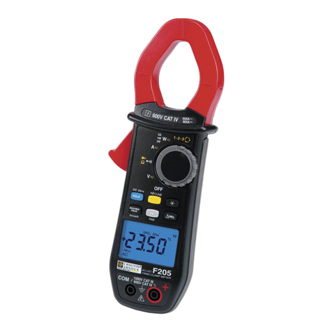
Clamp Multimeter F201 English
CONTENTS
1PRESENTATION........................................................................................................7
1.1 THESWITCH................................................................................................................. 8
1.2 THEKEYSOFTHEKEYPAD...................................................................................... 9
1.3 THEDISPLAYUNIT................................................................................................... 10
1.3.1 The symbols of the display unit....................................................................10
1.3.2 Measurement capacity exceeded (O.L)........................................................11
1.4 THETERMINALS ....................................................................................................... 11
2THE KEYS................................................................................................................. 12
2.1 KEY............................................................................................................................... 12
2.2 KEY(SECOND FUNCTION).............................................................................................. 12
2.3 KEY............................................................................................................................... 13
2.3.1 In the normal mode......................................................................................13
2.3.2 The MAX/MIN mode + activation of the HOLD mode................................. 14
2.3.3 Access to the True-INRUSH mode ( set to )...............................14
2.4 KEY............................................................................................................................... 15
2.4.1 The Hz function in the normal model...........................................................15
2.4.2 The Hz function + activation of the HOLD mode........................................15
3USE.............................................................................................................................16
3.1 COMMISSIONING...................................................................................................... 16
3.2 STARTINGUPTHECLAMPMULTIMETER.......................................................... 16
3.3 SWITCHINGTHECLAMP MULTIMETER............................................................. 16
3.4 CONFIGURATION...................................................................................................... 17
3.4.1 Programming of the maximum resistance allowed for a continuity............. 17
3.4.2 De-activation of automatic switching off (Auto Power OFF)......................17
3.4.3 Programming of the current threshold for the True INRUSH measurement18
3.4.4 Change of temperature measurement unit................................................... 18
3.4.5 Default configuration................................................................................... 19
3.5 VOLTAGEMEASUREMENT(V) ............................................................................. 19
3.6 CONTINUITYTEST .............................................................................................. 20
3.6.1 Automatic compensation of the resistance of the leads................................20
3.7 RESISTANCEMEASUREMENT.......................................................................... 21
3.8 DIODETEST ......................................................................................................... 21
3.9 CURRENTMEASUREMENT(A).............................................................................. 22
3.9.1 AC measurement.......................................................................................... 22
3.10 STARTINGCURRENTOROVERCURRENT(TRUEINRUSH)MEASUREMENT
........................................................................................................................................ 23
2
