Chauvin Arnoux L452 User manual

2
WARNING, risk of DANGER! The operator must refer to these instructions whenever this danger symbol appears.
Information or useful tip. Magnet.
Earth.
The product is declared recyclable following an analysis of the life cycle in accordance with standard ISO 14040.
Chauvin Arnoux has adopted an Eco-Design approach in order to design this appliance. Analysis of the complete life-
cycle has enabled us to control and optimize the effects of the product on the environment. In particular this appliance
exceeds regulation requirements with respect to recycling and reuse.
The CE marking indicates conformity with European directives, in particular LVD and EMC.
The rubbish bin with a line through it indicates that, in the European Union, the product must undergo selective disposal
in compliance with Directive WEEE 2002/96/EC. This equipment must not be treated as household waste.
PRECAUTIONS FOR USE
This instrument is compliant with safety standard IEC 61010-2-30, and the leads are compliant with IEC 61010-031, for voltages
of 30V with respect to earth. Failure to observe the safety instructions may result in electric shock, re, explosion, and destruction
of the instrument and of the installations.
The operator and/or the responsible authority must carefully read and clearly understand the various precautions to be taken in
use. Sound knowledge and a keen awareness of electrical hazards are essential when using this instrument.
Do not use the instrument on networks of which the voltage exceeds those mentioned.
Never exceed the protection limits stated in the specications.
Observe the conditions of use, namely the temperature, the relative humidity, the altitude, the degree of pollution, and the place
of use.
Do not use the instrument if it seems to be damaged, incomplete, or poorly closed.
Before each use, check the condition of the insulation on the leads, housing, and accessories. Any item of which the insulation is
deteriorated (even partially) must be set aside for repair or scrapping.
Do not use this instrument in an explosive atmosphere or in the presence of ammable gases or vapours.
Before using your instrument, check that it is perfectly dry. If it is wet, it must be thoroughly dried before it can be connected or used.
Use only cables and accessories consistent with the specications of the instrument.
Use personal protection equipment systematically.
All troubleshooting and metrological checks must be done by competent, accredited personnel.
Thank you for purchasing an L452 Data Logger.
For best results from your instrument:
read these operating instructions carefully,
comply with the precautions for use.

3
CONTENTS
1. FIRST USE................................................................................................................................................................................ 4
1.1. Delivery condition ........................................................................................................................................................... 4
1.2. Accessories .................................................................................................................................................................... 4
1.3. Spare parts..................................................................................................................................................................... 5
1.4. Battery charging ............................................................................................................................................................. 5
2. PRESENTATION OF THE INSTRUMENT ................................................................................................................................ 6
2.1. Functions of the instrument ............................................................................................................................................ 6
2.2. Side view ....................................................................................................................................................................... 6
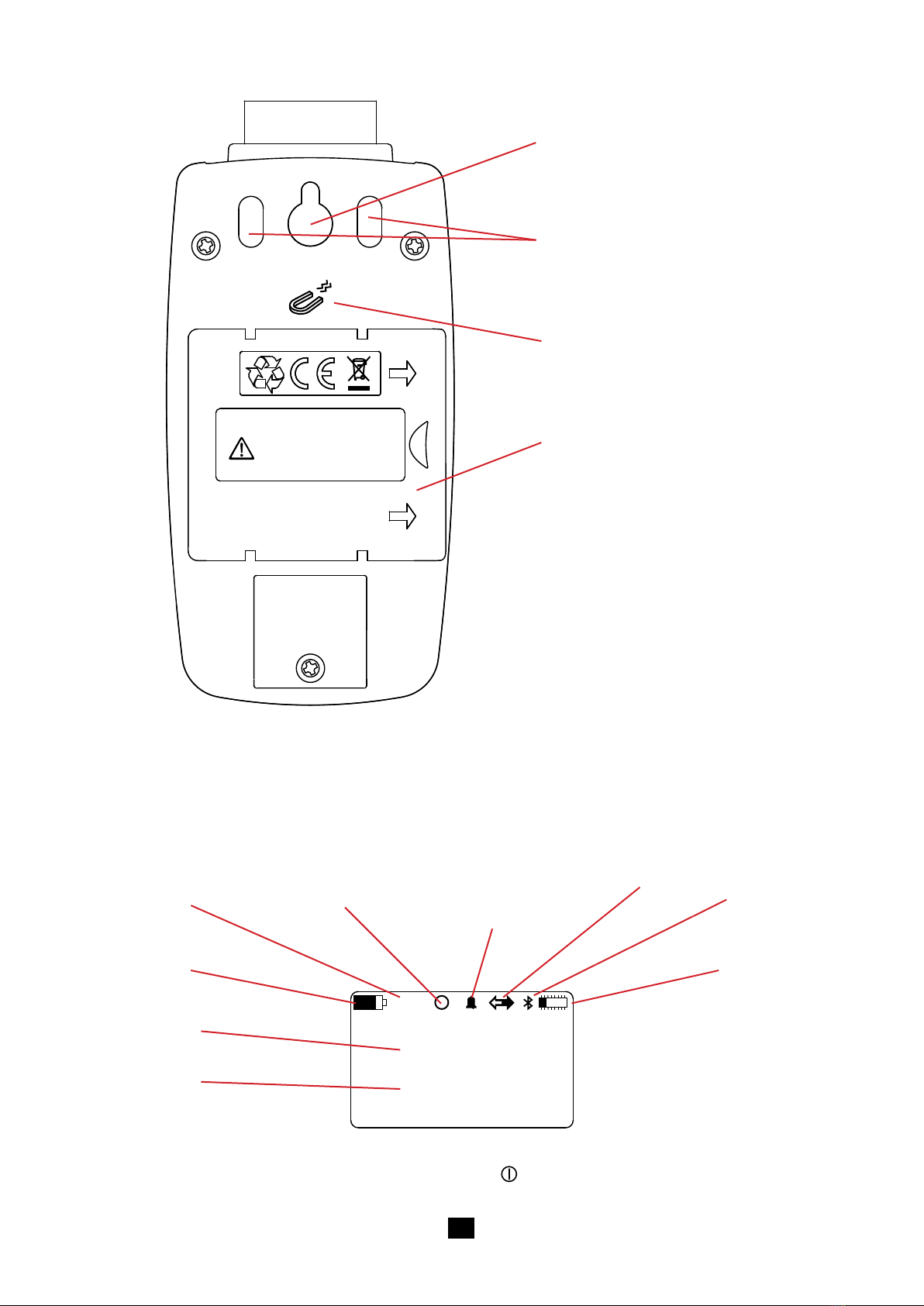
2.3. On the back .................................................................................................................................................................... 7
2.4. Display unit..................................................................................................................................................................... 7
3. SETTINGS OF THE INSTRUMENT.......................................................................................................................................... 8
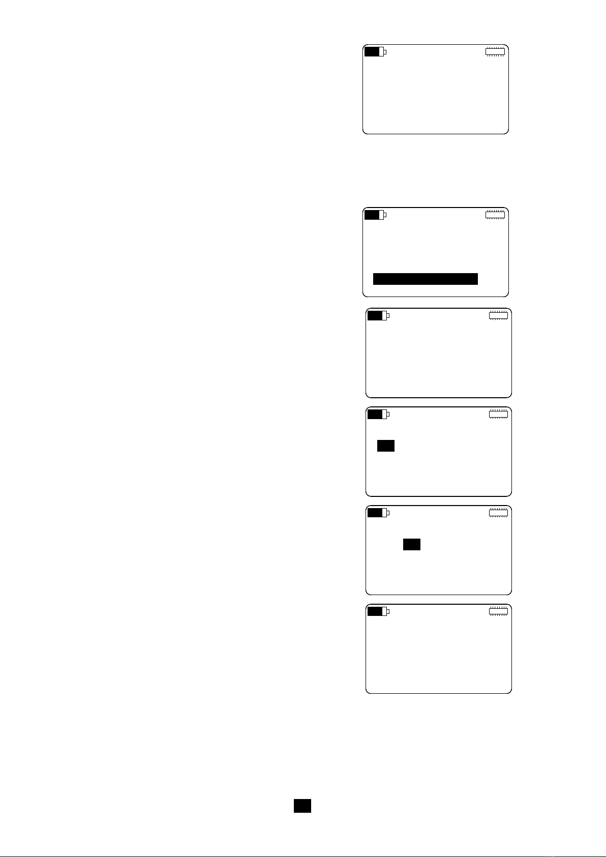
3.1. Organization of the screens............................................................................................................................................ 8
3.2. Choosing a language...................................................................................................................................................... 8
3.3. Setting the time and date................................................................................................................................................ 9
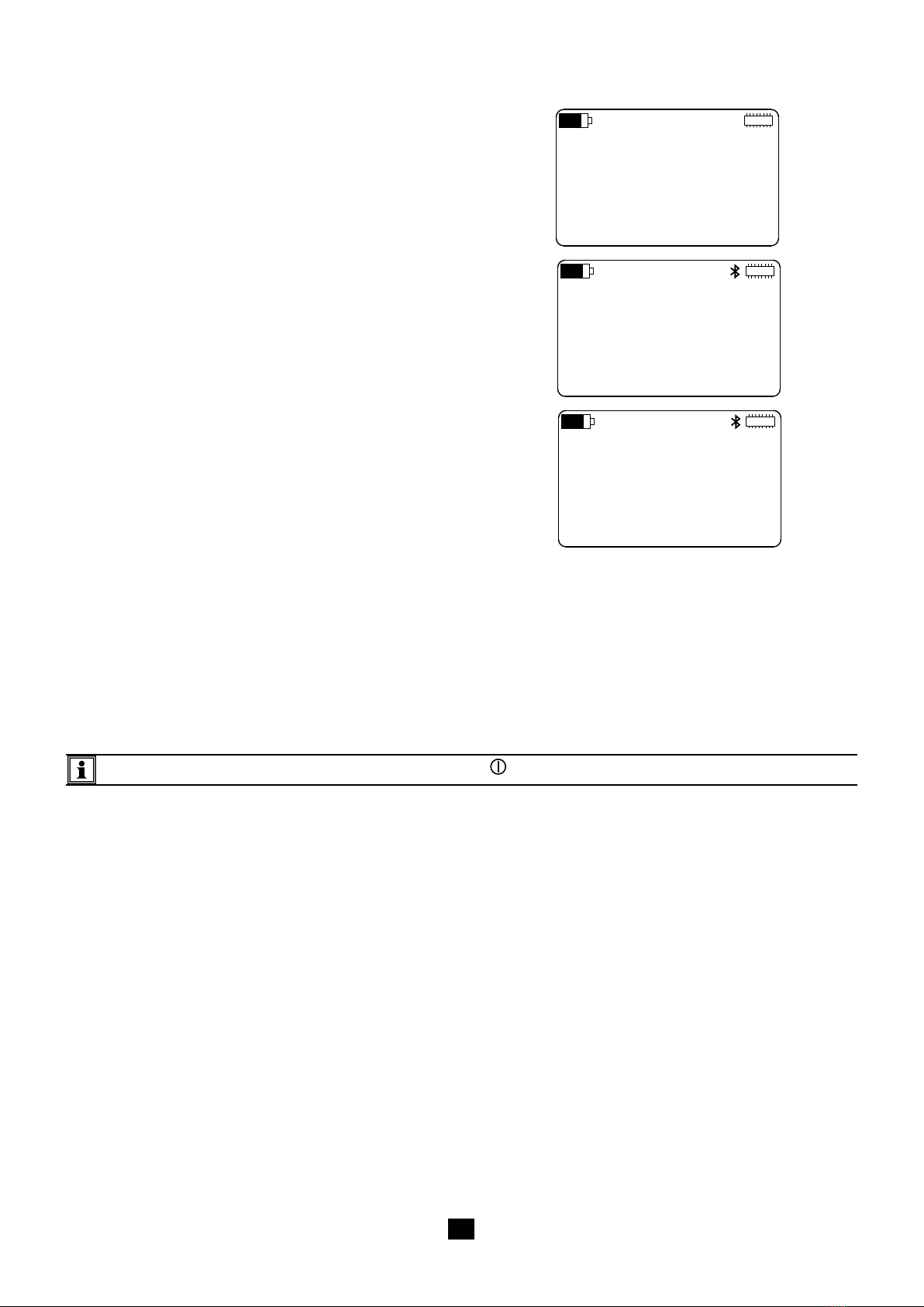
3.4. Conguring the Bluetooth link....................................................................................................................................... 10
3.5. Restoring the original conguration...............................................................................................................................11
3.6. Display of product information.......................................................................................................................................11
3.7. Switching the instrument off ......................................................................................................................................... 12
4. USE ......................................................................................................................................................................................... 13
4.1. Changing a parameter.................................................................................................................................................. 13
4.2. Conguring the measurement channels....................................................................................................................... 13
4.3. Connecting probes, sensors, transmitters, or signal conditioners................................................................................ 15
4.4. Display of the measurements....................................................................................................................................... 15
4.5. Recording data ............................................................................................................................................................. 17
4.6. Clearing memory .......................................................................................................................................................... 19
5. DATA LOGGER TRANSFER SOFTWARE ............................................................................................................................ 20
5.1. Functions...................................................................................................................................................................... 20
5.2. Installation ................................................................................................................................................................... 20
5.3. USB connection............................................................................................................................................................ 20
5.4. Bluetooth communication ............................................................................................................................................. 21
5.5. Remote mode............................................................................................................................................................... 22
6. TECHNICAL CHARACTERISTICS ........................................................................................................................................ 23
6.1. Reference conditions.................................................................................................................................................... 23
6.2. Electrical characteristics............................................................................................................................................... 23
6.3. Power supply................................................................................................................................................................ 23
6.4. Memory......................................................................................................................................................................... 24
6.5. Bluetooth ...................................................................................................................................................................... 24
6.6. USB .............................................................................................................................................................................. 24
6.7. Environmental conditions ............................................................................................................................................. 24
6.8. Mechanical characteristics ........................................................................................................................................... 25
6.9. Compliance with international standards...................................................................................................................... 25
6.10. Electromagnetic compatibility (CEM).......................................................................................................................... 25
7. MAINTENANCE...................................................................................................................................................................... 26
7.1. Cleaning ....................................................................................................................................................................... 26
7.2. Replacing the batteries................................................................................................................................................. 26
7.3. Updating the embedded software................................................................................................................................. 26
8. WARRANTY ........................................................................................................................................................................... 27

4
1. FIRST USE
1.1. DELIVERY CONDITION
Figure 1
1One L452 Data Logger.
2Two 1.2V, 2400mA NiMH batteries.
3One USB A / micro USB cord 1.80m long.
4One USB mains adapter.
5One connecting strip with 6 screw terminals.
6One CD containing the user manual (1 le per language) and Data Logger Transfer software.
7One multilingual getting started guide.
8One certicate of verication.
1.2. ACCESSORIES
One wall mount
190,rue Championnet
75876PARIS Cedex 18
ATTESTATION DE VERIFICATION
CHECKING ATTESTATION
Numéro de l'appareil :
Nous certifions que ce produit a été fabriqué conformément aux spécifications
techniques de constuction applicables.
We certify that this product is manufactured in accordance with applicable
constructing specifications.
907009 119 - 02/03
FRANCE
Equipment number
Établien usine, ce document atteste que le produit ci-dessus a été vérifié et est conforme aux
conditionsd'acceptation définies dans nos procédures de fabrication et de contrôle.
Tousles moyens de mesure et d'essai utilisés pour vérifiercet appareil sont raccordés aux
étalonsnationaux et internationaux soit par l'intermédiaire d'un de nos laboratoires de métrologie
accréditésCOFRAC soit par un autre laboratoire accrédité.
Aprèssa mise en service, cet instrument doit être vérifié à intervalle régulier
auprèsd'un service de métrologie agréé.
Pourtout renseignement veuillez contacter notre service après vente et d'étalonnage.
Atthe time of manufacture, this document certifies that the above product have been verifiedand
complieswith acceptance conditions defined in our manufacturingand testing procedures.
Everytest or measuring equipment used to verify this instrument are related to national
andinternational standards through one of our laboratories of metrology certified by french COFRAC
equivalentto NAMAS in the UK or through another certified laboratory.
Afterbeing in use, this instrument must be recalibrated within regular intervals
byan approved metrology laboratory.Please contact our after sales and calibration department:
Serviceaprès vente et d'étalonnageTEL: +33(2) 31 64 51 55 FAX: +33 (2) 31 64 51 72
Aftersales and calibration departmente-mail:info@manumesure.fr
WEB: www.manumesure.com
www.chauvin-arnoux.com
Vérifié par :
Testedby
ATTESTATION DE CONFORMITE
COMPLIANCE ATTESTATION
Type/
Model
:
Désignation de l'instrument :
Instrument designation
Signature :
Signature
➀
➅
➄
➃
➁➂
➆
➇
V
INPUT 1 INPUT 2
VmA mA
30V
MAX
L452
SIMPLE LOGGER III
This is attached to the wall, and makes
it possible to protect the instrument
against theft by padlocking it.
Figure 2

5
1.3. SPARE PARTS
One USB mains adapter and one USB A / micro USB cord 1.80m long.
One set of 5 connecting strips with 6 screw terminals.
One set of two 1.2V, 2400mA NiMH batteries.
For accessories and spares, visit our web site:
www.chauvin-arnoux.com
1.4. BATTERY CHARGING
Turn the instrument over.
Remove the battery compartment cover by pushing it as far as the marks in the direction indicated by the arrows, then lifting it off.
Insert the 2 batteries provided, paying attention to the polarity.
Figure 3
Put the battery compartment cover back on and push it closed.
Connect the micro USB cord to the instrument, then the USB part to the mains adapter.
> 90 VAC
< 264 VAC
50 / 60 Hz
Figure 4
If the batteries are fully discharged, charging takes approximately 5 hours.

6
2. PRESENTATION OF THE INSTRUMENT
2.1. FUNCTIONS OF THE INSTRUMENT
The L452 Data Logger is a two-channel recorder. It can be powered either by the rechargeable batteries or by mains, via a USB cable.
It is used:
to record DC voltages up to 10V,
to record direct currents from 4 to 20mA,
to count pulses,
to detect events on its discrete inputs.
The voltage and current measurements can be sampled at intervals from 200ms to 1 minute. The sampled quantities can be av-
eraged (means) over periods from 200ms to 1 hour and recorded in the internal memory.
The L452 Data Logger is used to check and measure process applicaons, water, gas, and power meters, or to monitor
the environment. It can operate in the local mode or in the remote mode. It can communicate by USB or by Bluetooth.
2.2. SIDE VIEW
Connecting strip.
LCD graphic display unit.
Micro USB connector.
4 browsing keys and
one validation key.
On/Off key.
V
INPUT 1 INPUT 2
VmA mA
30V
MAX
L452
SIMPLE LOGGER III
Figure 5
Terminal block..

7
2.3. ON THE BACK
MADE IN FRANCE
USE ONLY SPECIFIED
POWER SUPPLY
2 x AA 1.2V RECHARGEABLE BATTERY
Notch for hanging the instrument.
Non-skid pads.
Magnet for attachment to a metallic surface.
Battery compartment cover.
2.4. DISPLAY UNIT
A typical measurement screen looks like this:
OL
1
2
mV
mV
24.5
91.8
Figure 7
This screen is called Measurement data. To open it, press the On/Off key briey.
Figure 6
Battery: indicates
the charge state.
Overload: indicates
that the meas-
urement is out of
bounds.
Recording: indicates that
a recording session is sched-
uled and indicates that
recording is in progress. Alarm: indicates an
alarm in one of the
channels.
Remote mode: indi-
cates that the remote
mode is activated. Bluetooth: indicates
that Bluetooth is ac-
tivated.
Memory: indicates
the space available
at memory.
Value measured in
channel 1.
Value measured in
channel 2.

8
3. SETTINGS OF THE INSTRUMENT
Before you use the L452 for the rst time, you must congure it. It can be congured either in the local mode (on the keys of the
instrument itself) or in the remote mode (using the Data Logger Transfer software).
The parameters to be congured are:
The language,
The date and time,
Activation or non-activation of the Bluetooth link,
Activation or non-activation of the visibility of the instrument on the Bluetooth network,
The name of the instrument for the Bluetooth link.
3.1. ORGANIZATION OF THE SCREENS
The screens are organized into 6 categories.
The measurement screens display the measured data (including the minimum and maximum values) of the two input channels.
They can be accessed directly by switching the instrument on.
The recording screens, used to start, stop, schedule, and congure recording sessions.
They can be accessed by pressing the key once.
The channel 1 conguration screens, used to activate the channel and dene the type of input, the measurement unit, the
transformation coefcient, and the alarm.
They can be accessed by pressing the key twice.
The channel 2 conguration screens, used to activate the channel and dene the type of input, the measurement unit, the
transformation coefcient, and the alarm.
They can be accessed by pressing the key three times.
The conguration screens of the instrument, used to dene the language, the date and time, and the Bluetooth link. They are
also used to clear the memory, to reset the conguration, and to reset the minimum and the maximum.
They can be accessed by pressing the key four times.
The instrument information screens, which are read-only and display the serial number, the internal software version, the name
of the instrument on the Bluetooth network, and the state of the memory.
They can be accessed by pressing the key ve times.
3.2. CHOOSING A LANGUAGE
Switch the instrument on by pressing the On/Off key and keeping it pressed until the display unit indicates POWER ON.
The Measurement data screen (see Figure 7) is displayed.
LANGUAGE:
ENGLISH
DATE/TIME:
MM/DD/YY 24h
Press to select the eld.
Press 4 times
LANGUAGE:
ENGLISH
DATE/TIME:
MM/DD/YY 24h

9
Press again to edit the eld, then or to scroll through
the 5 possible languages (English, French, Spanish, Italian,
and German), and nally to validate.
LANGUAGE:
ENGLISH
DATE/TIME:
MM/DD/YY 24h
3.3. SETTING THE TIME AND DATE
LANGUAGE:
ENGLISH
DATE/TIME:
MM/DD/YY 24h
From the previous screen, press to select the eld, then
to go to the next eld. Press again to edit the eld, then
or to scroll through the 4 possible choices:
MM/DD/YY AM/PM
MM/DD/YY 24h
DD/MM/YY AM/PM
DD/MM/YY 24h
Press to validate your choice, then 3 times.
DATE:
01/01/00
TIME:
00:01:15AM
Press to select the rst eld, then again to edit the eld.
Then or to dene the rst eld.
DATE:
01/01/00
TIME:
00:01:15AM
Press to go to the next eld, then or to dene the eld.
Press again to go to the third eld, then or to dene
it. Press to validate.
DATE:
09/01/00
TIME:
00:01:15AM
Proceed in the same way for the time.
DATE:
09/12/15
TIME:
09:37:25AM

10
Proceed as for the previous adjustments to activate the
Bluetooth link and make it visible, at least until the instrument
is connected to the PC. After that, you may make it invisible
once again.
BLUETOOTH:
ENABLED
VISIBILITY:
VISIBLE
Press and the display unit indicates the name under which
the instrument will appear on the PC.
You can change this name, character by character, using the
and keys to go from one character to another. The header
(L452-) cannot be changed.
BLUETOOTH
NAME:
L452-452105MLP
The characters available for the name are all the characters of the ASCII and extended ASCII tables:
numerals
upper-case letters
lower-case letters
special characters such as: ! “ # $ % & ‘ ( ) * + , - . / : ; < = > ? @ [ \ ] ^ _ { | } ~
special letters such as: Ç ü é â ä à å ç ê ë è ï î ì Ä etc.
other characters such as: ░ ▒ ▓ ≤ ≥ ├ ┤ ┐ ┌ ┼ ┴ ┬ ■ □ ● etc.
The space is the last character. To reach it from !, press .
Holding the or key down accelerates the scrolling of the characters.
To return to the Measurement data screen, press the On/Off key.
3.4. CONFIGURING THE BLUETOOTH LINK
From the previous screen, press .
BLUETOOTH:
DISABLED
VISIBILITY:
INVISIBLE

11
Switch the instrument on, press four times and twice.
CONFIGURATION:
NO ACTION
Press twice, then the or key to display RESET,and
nally to validate.
The instrument asks for conrmation.
RESET CONFIG?
PRESS ENTER
TO CONFIRM
To cancel, press and simultaneously. To conrm, press .
3.5. RESTORING THE ORIGINAL CONFIGURATION
You can cancel all of the changes you have made to the conguration by resetting the instrument.
Only the date, the time, and the content of the memory will remain.
3.6. DISPLAY OF PRODUCT INFORMATION
The information in this menu can be looked up but not modied.
L452
SN: 452101MLP
Firmware: 1.00
NAME:
LOCATION:
L452-452105MLP
CHAUVIN ARNOUX
From the Measurement data screen, press ve times. You
can see:
The reference of the instrument (L452),
The serial number,
The internal software version,
Press . You can see:
The name of the instrument for the Bluetooth network,
The location of the instrument. The only way to specify
this is via the Data Logger Transfer software.
Press . You can see:
The number of recording sessions stored in memory,
The available memory.
RECORDING
SESSIONS: 0
FREE
MEMORY:31.88 MB

12
To return to the Measurement data screen, press the On/Off key.
3.7. SWITCHING THE INSTRUMENT OFF
To switch the instrument off, press the On/Off key and hold it down until the instrument displays POWER OFF.
Press . You can see the default name of the next recording
session.
This name is the name of the instrument plus a session number
that is incremented each time. It can be modied via the Data
Logger Transfer software.
RECORDING
NAME:
L452-452105MLP 1

13
4. USE
Once your instrument has been congured, you can use it. You must still:
Congure the measurement channels,
Connect the probes, sensors, transmitters, or signal conditioners
Start a recording session
4.1. CHANGING A PARAMETER
To change a parameter, press ; this changes the rst eld on the screen that can be modied to reverse video. Use the
keys to select the eld you want to modify, then press again to edit the eld. Then use the or key to dene the eld. If
the eld comprises several characters, use the or key to go from one character to another.
When you have nished, press to validate.
The numbers are not changed digit by digit, but more globally.
For example, to go from 0.00 to 85.00, start on the left-hand digit, before the zero, and press . The digit will be incremented
repeatedly. When it reaches 8, shift the cursor to the second digit and change it in the same way. And so on.
For a negative number, start on the left-hand digit, before the zero, and press . The digit changes to 00.00, then to -10.00, then
-20.00, etc.
4.2. CONFIGURING THE MEASUREMENT CHANNELS
From the Measurement data screen (see Figure 7), press twice.
From this screen, you can activate or deactivate measurement
channel 1 and choose the type of input:
pulse
event (discrete)
4-20mA current
±10V, ±1V, or ±100mV voltage
CHANNEL 1:
ENABLED
INPUT:
±100 mV
It is not possible to deactivate both channels. If you deactivate channel 2 when channel 1 is already deactivated, channel
1 is automatically reactivated. This makes it impossible to start a recording session with both channels deactivated by
mistake.
UNITS:
CHANNEL 1:
Press to go to the next screen and enter the unit of channel
1 in 4 characters.
If you do not specify a unit, the default values will be:
mV for ±100 mV
V for ±10V and ±1 V
mA for 4-20 mA
Wh for pulse
For an event input, you can choose whether triggering is on
the positive-going or negative-going front.
TRIGGER:
RISING

14
SCALE LOW:
0.0 mV
= 0.0 mV
CHANNEL 1:
SCALE HIGH:
100.0 mV
= 100.0 mV
CHANNEL 1:
EQUIVALENCE:
1.00 Pulse
= 1.00 Wh
CHANNEL 1:
Press . The next 2 screens are used to dene transformation
coefcients for the current and voltage inputs.
For example, if you use a temperature sensor that delivers 4mA
at -10°C and 20mA at 100° C, you enter:
Input: 4-20 mA
Unit: degC
Scale Low: 4.0 mA = -10 degC
Scale High: 20.0 mA = 100 degC
The instrument then displays the measurement directly in °C.
For a pulse input, you can dene the number of pulses that
corresponds to a certain power, or to something else, since
you can change the unit.
For example, if you count the number of teeth on a toothed ring
and know that one revolution corresponds to 14 teeth (hence
14 pulses), you can enter "14 pulses = 1 revolution".
Press . The next screen is used to dene alarms for the
current and voltage inputs.
The alarm can be triggered when:
the measurement is above the high limit,
the measurement is below the low limit,
the measurement is either above the high limit or below
the low limit,
the measurement is within the limits.
The alarm can also be deactivated.
ALARM TRIGGER:
OUTSIDE LIMITS
UPPER LIMIT:
0.00 mV
LOWER LIMIT:
0.00 mV
Press to dene the high and low limits. If you have dened
transformation coefcients, they will be displayed directly in
the unit dened.
To return to the example of the temperature sensor, the limits
will be 100 degC and -10 degC.
Press to go to the conguration of channel 2 and proceed
as for channel 1.
±100 mV
CHANNEL 2:
ENABLED
INPUT:
Both measurement channels must have the same type of input. If you set input 2 to pulse and input 1 was voltage, channel
1 automatically changes to pulse.
The upper limit must be greater than the lower limit. If you program a lower limit that is above the upper limit, the instrument
sets both limits to the same value.

15
4.3. CONNECTING PROBES, SENSORS, TRANSMITTERS, OR SIGNAL CONDITIONERS
The L452 Data Logger operates with a great variety of probes having outputs of the following type:
Voltage: ± 100 mV, ± 1 V or ± 10 V
Current: 4 - 20 mA
Pulse: ± 10 V
On/Off (discrete): ± 10 V
Place the connecting strip provided on the terminal block of the instrument and push it home.
V
INPUT 1 INPUT 2
VmA mA
30V
MAX
L452
SIMPLE LOGGER III
Figure 8
Then connect the probes.
V
INPUT 1 INPUT 2
VmA mA
30V
MAX
V
INPUT 1 INPUT 2
VmA mA
30V
MAX
Channel 1 Channel 1
Figure 9
Use a small at blade screwdriver to unscrew the screws of the terminal block. Insert the wires, then screw the screws back in so
that the wires cannot be pulled out of the connector.
4.4. DISPLAY OF THE MEASUREMENTS
4.4.1. CURRENT OR VOLTAGE INPUTS
Once the probes have been connected, switch the instrument on. The display unit indicates the values on the measurement inputs.
1
2
m3/s
mmHg
2.53
9.75
4-20mA current probe Voltage, pulse, or discrete probe.
Channel 2 Channel 2
Figure 10

16
If the measurement from one of the channels is outside of the
measurement range, the instrument displays OL.
Check that the probe you have connected delivers the right signal
and that the type of input is the right one.
Press to display the minimum and maximum of channel 1.
Press to display the minimum and maximum of channel 2.
The values displayed on this screen are not the instantaneous
values displayed on the Measurement data screen, but averages
over the storage period.
The minimum and maximum are reset:
at the beginning of a recording session,
when the type of input is changed,
when the sampling period or the storage period is changed,
when the instrument is off.
1
2
m3/s
mmHg
2.53
OL
OL
1m3/s
2.54
Max: 3.68 m3/s
Min: 0.22 m3/s
Figure 11
You can also reset them manually.
From the Measurements data screen (see Figure 10), press
four times, then once.
Choose Reset for Min/Max. The instrument asks for conrmation.
To cancel, press and simultaneously. To conrm, press .
MEMORY:
NO ACTION
MIN/MAX:
NO ACTION
4.4.2. PULSE INPUTS
Instead of the minimum and maximum screens, the instrument in-
dicates the period of storage corresponding to the maximum value.
1Wh
91
DATE: 09/15/15
TIME: 11:25:32AM
4.4.3. EVENT INPUTS
The Measurement data screen takes a different form.
1
2

17
Press to display the graphic representation of the last event
of channel 1.
1
DATE: 09/15/15
TIME: 11:28:17AM
4.5. RECORDING DATA
The L452 can store up to 1024 recording sessions.
The size of a recording session depends on the storage period and on the duration of the record. This last is limited by the battery
life of the instrument.
The recorded sessions can be uploaded to a PC (see §5) to be saved, displayed, and analysed.
Before starting a recording, make sure that there is enough space in memory. If the memory is full ( ) or nearly full ( ), you
must empty it (see §4.6) to be able to make new records.
You can also look at the number of recording sessions (see §3.6), the maximum being 1024, and the available memory size, the
maximum being 31.88 MB.
From the Measurement data screen (see Figure 10), press .
RECORDING:
START
DURATION:
15 min
Press .
Dene the sampling period, between 200ms and 1 minute.
The possible values are: 200ms, 400ms, 600ms, 800ms, 1 to
60 seconds, and 1 minute.
Then dene the storage period, between 200ms and
1 hour. The possible values are: 200ms, 400ms, 600ms,
800ms, 1 to 60 seconds, and 1 to 60 minutes.
SAMPLE PERIOD:
200 ms
STORAGE PERIOD:
01 s
The storage period must be longer than the sampling period. If you set the storage period to a smaller value than the sam-
pling period, the sampling period is automatically changed so as to be equal to the storage period.
For an event input, this screen is read-only. The sampling period is xed: 62.5ms.
The samples are averaged over the storage period, then recorded and displayed on the Min/Max screen (see Figure 11).
The shorter the sampling period, the more measurements the instrument must make and the shorter its life between charges.
The shorter the storage period, the more data the instrument must record: the averaged measurements, the minimum and
maximum values.
If the sampling and storage periods are different, the instrument must record ve times as much data. In that case, it is best to
choose a storage period at least ve times as long as the sampling period.

18
Press . Choose a recording duration between 1 minute and
99 weeks. Bear in mind that the life between charges of the
instrument is not that long (see § 6.3).
The recording time must be at least as long as the storage
period.
START DATE:
09/15/15
START TIME:
10:00:00AM
STOP DATE:
09/15/15
STOP TIME:
02:00:00PM
RECORDING:
START
DURATION:
15 min
You can start recording immediately by pressing 3 times.
The symbol is displayed.
Proceed in the same way if you want to stop recording before
the end of the programmed recording time.
If recording fails to start, it means that there is not enough
available space in memory for the recording. You must clear
the memory (see §4.6) to be able to record your session.
RECORDING:
STOP
DURATION:
15 min
You can also program the start- and end-of-recording times.
Press twice and choose the starting and stopping times.
The duration is adjusted automatically.
Or program the duration and the ending time is adjusted.
Press . Change the text Start to Schedule and validate by
pressing . Recording is pending and will begin at the sched-
uled time. The symbol is displayed.
To cancel a programmed recording session, press three
times.
RECORDING:
CANCEL
DURATION:
4 hours
You cannot switch the instrument off while recording is in progress.
If you press the On/Off key, the instrument displays the screen
opposite and does not switch off.
But it is possible to switch it off if a recording session is pro-
grammed. The instrument will switch itself back on for the duration
of the recording, then switch off automatically.
RECORDING
ACTIVE
It is not possible to modify the conguration while recording is in progress. To change it, you must stop recording.

19
4.6. CLEARING MEMORY
If you want to preserve recorded sessions, transfer them to a PC (see §5) before clearing the memory of the instrument.
From the Measurement data screen (see Figure 10), press 4
times, then once.
Choose Erase for the memory.
MEMORY:
NO ACTION
MIN/MAX:
NO ACTION
ERASE MEMORY?
PRESS ENTER
TO CONFIRM
The instrument asks for conrmation.
To cancel, press and simultaneously.
To conrm, press .
The instrument displays the progress of the erasure of the memory,
which can take several minutes.
During this time, the keys of the instrument are inoperative.
ERASING MEMORY

20
5. DATA LOGGER TRANSFER SOFTWARE
5.1. FUNCTIONS
The Data Logger Transfer software is used to:
Connect the instrument to the PC, using either USB or Bluetooth.
Congure the instrument: choose the language, set the date and time, activate or deactivate the Bluetooth link (the latter only
if connected by USB), activate or deactivate visibility of the instrument on the Bluetooth network and give it a name, etc.
Congure the measurement channels.
Congure the records: choose their names, their duration, their start and end dates.
Start and stop recording.
Data Logger Transfer is also used to upload recorded sessions to a PC to save them, display them, or analyse them. And nally
to export them to a spreadsheet and view the corresponding curves.
5.2. INSTALLATION
Do not connect the instrument to the PC until the software and driver have been installed.
Insert the CD in the CD-ROM drive.
Figure 12
If automatic execution is activated, the program starts automatically.
If not, select Setup.exe
Then follow the instructions to install the program.
To use the Data Logger Transfer software, refer to its help function.
5.3. USB CONNECTION
Once the software and the driver have been installed, you can connect the instrument to the PC.
Figure 13
V
INPUT 1 INPUT 2
VmA mA
30V
MAX
L452
SIMPLE LOGGER III
Other manuals for L452
1
Table of contents
Popular Other manuals by other brands

IBM
IBM HS21 BLADECENTER - FOR SPECJAPPSERVER2004 specification

SGS
SGS SSB100 owner's manual

Kathrein
Kathrein RRU 4 series user guide

Kohler
Kohler Skyline Pivot Pentagon installation guide

HID Corporation
HID Corporation MIFARE WIEGAND READER 6074A installation manual

First Alert
First Alert 2060DF Operations & installation guide