CHD 8-440 User manual
7
Model 8-440
ver. 1.0
INSTALLATION MANUAL
© 2015 CHD Elektroserv is
VP330-KBD
Roland VP-330 MIDI Interface
Model 8-440 ver. 1.0
Copyright © 2015 CHD Elektroservis. All rights reserved.
No part of this publication may be reproduced in any form without the written permission of CHD Elektroservis.
2
Content
page
1. General information . . . . . . . . . . . . . . . . . . . . . . . . . . . . . . . . . . . 3
1.1. Parts of MIDI interface kit . . . . . . . . . . . . . . . . . . . . . . . . . . . . . . . . 3
2. MIDI interface installation . . . . . . . . . . . . . . . . . . . . . . . . . . . . . . . . 4
2.1. Opening the instrument . . . . . . . . . . . . . . . . . . . . . . . . . . . . . . . . . 4
2.2. MIDI sockets montage . . . . . . . . . . . . . . . . . . . . . . . . . . . . . . . . . 5
2.3. Switch and indication LED montage . . . . . . . . . . . . . . . . . . . . . . . . . . 6
2.4. Montage of power supply bunched cables . . . . . . . . . . . . . . . . . . . . . . . 8
2.5. Montage of flat control signals cable . . . . . . . . . . . . . . . . . . . . . . . . . . 8
2.6. Montage of the interface board . . . . . . . . . . . . . . . . . . . . . . . . . . . . . 12
2.7. Finishing of the installation . . . . . . . . . . . . . . . . . . . . . . . . . . . . . . . 14
3. Tips for installation . . . . . . . . . . . . . . . . . . . . . . . . . . . . . . . . . . . 15
This manual in PDF form is available on supplemental CD-ROM or on manufacturer’s web-pages.
Manufacturer :
CHD Elektroservis
Nad kundratkou 27, 19000 Praha 9
Czech Republic
info@chd-el.cz
www.chd-el.cz

VP330-KBD
Roland VP-330 MIDI Interface
Model 8-440 ver. 1.0
Copyright © 2015 CHD Elektroservis. All rights reserved.
No part of this publication may be reproduced in any form without the written permission of CHD Elektroservis.
3
1. GENERAL INFORMATION
VP330-KBD MIDI interface allows full integration of Roland VP-330 instrument to MIDI system.
Interface affects instrument’s keyboard and pitch shift function. All original features of VP-330
instrument remain unchanged after the interface installation and the instrument can be used the same
way as without interface installed. Simplified block functional schematic of the instrument after the
interface installation is shown on pic. 1.
Pic. 1 – Connection to instrument
1.1. PARTS OF MIDI INTERFACE KIT
MIDI interface kit includes all parts necessary for installation incl. all support and coupling
elements. Installation manual, user manual, description of interface’s SysEx communication and CD-
ROM with support software is also included. Please check the part list whether the delivery is complete
before installation (see pic. 1.1).
Pic. 1.1 – Parts of interface kit
VP330-KBD
Roland VP-330 MIDI Interface
Model 8-440 ver. 1.0
Copyright © 2015 CHD Elektroservis. All rights reserved.
No part of this publication may be reproduced in any form without the written permission of CHD Elektroservis.
4
The VP330-KBD-M interface kit delivery contains :
1. MIDI Interface board
2. Bunched cables with tumbler switch and LED
3. 2x DIN-5 socket with cable
4. Flat control signals cable (50-wire)
5. Power supply bunched cables (4-wire)
6. Shielded cable
7. Coupling elements (screws, supports, tightening strips …)
8. CD-ROM with support software and manuals in PDF form
9. 3x manual in printed form
2. MIDI INTERFACE INSTALLATION
Installation of the interface into Roland VP-330 instrument is very easy. If you follow the
instruction from this manual carefully, there should be no major problems during the installation
procedure. Detailed steps of interface’s parts installation is described in chapters below. Please keep
these instructions accurately to not damage the instrument.
Attention! Disconnect the instrument form the mains prior to the installation.
Otherwise, there is a risk of the electric shock!
Attention! Observe precautions for handling electrostatic discharge sensitive devices!
The producer is not responsible for any eventual mechanical or electrical damage of
the VP-330 instrument caused by the infringement of the described installation
procedure or by careless manipulation during the installation of the MIDI interface!
2.1. OPENING THE INSTRUMENT
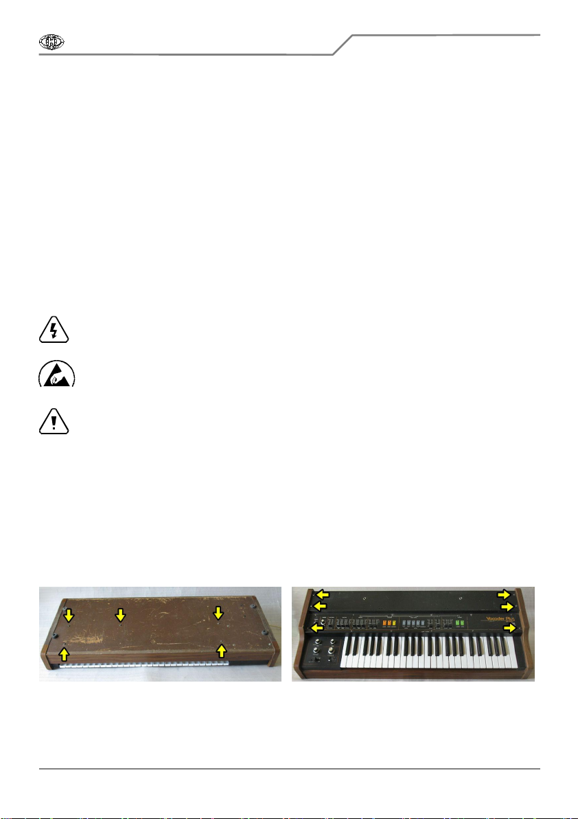
a) Unscrew five screws on bottom side of the instrument (pic. 2.1.1). Keep the screws. They will
be used again after the MIDI kit installation is finished. Remark: These screws hold instrument’s
keyboard to bottom plate of instrument’s cover.
b) Unscrew six screws on top panel of the instrument (pic. 2.1.2). Keep the screws. They will be
used again after the MIDI kit installation is finished. Remark: These screws hold instrument’s top panel.
Pic. 2.1.1 Pic. 2.1.2
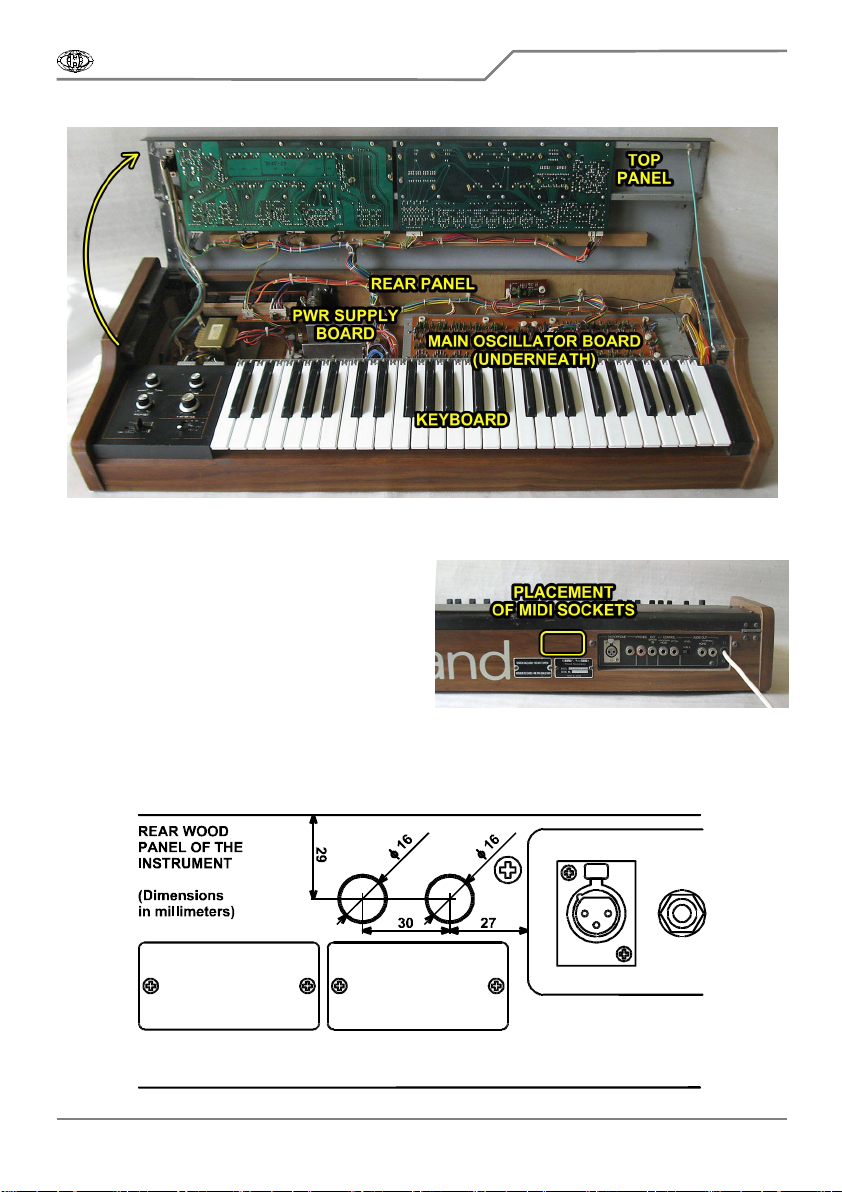
c) Carefully open the instrument - lift off the instrument’s panel. Now, all instrument’s parts and
boards needed for the interface installation are accessible (pic. 2.1.3).
VP330-KBD
Roland VP-330 MIDI Interface
Model 8-440 ver. 1.0
Copyright © 2015 CHD Elektroservis. All rights reserved.
No part of this publication may be reproduced in any form without the written permission of CHD Elektroservis.
5
Pic. 2.1.3
2.2. MIDI SOCKETS MONTAGE
Pic. 2.2.1
The interface has both MIDI input and output.
Only MIDI input is necessary for the interface
operation. MIDI output need not to be installed –
see chapter 5. However, both MIDI input and
output (MIDI-IN and MIDI-THRU/OUT sockets)
utilization is more convenient for full
interconnection to MIDI system. Suitable place for
MIDI sockets is on rear panel of the instrument
(see pic. 2.2.1).
P
a) Drill two holes with diameter 16 mm for MIDI sockets to the wood rear panel of the instrument
– see pic. 2.2.2. Use sharp drill and work carefully so that the panel and a components inside the
instrument are not damaged during drilling!
Pic. 2.2.2

VP330-KBD
Roland VP-330 MIDI Interface
Model 8-440 ver. 1.0
Copyright © 2015 CHD Elektroservis. All rights reserved.
No part of this publication may be reproduced in any form without the written permission of CHD Elektroservis.
6
b) Clean the edge of both holes with small rasp after drilling. Clean all sawdust and rasping
from the inside of the instruments, they can cause malfunction of some electro-mechanical
components of the instrument. Please clean the instrument carefully!
c) Get flat connectors of MIDI cables through the holes in the panel (pic. 2.2.3). Both MIDI cables
are identical and they can be swapped.
Pic. 2.2.3 Pic. 2.2.4
d) Insert DIN sockets of the cables into the drilled holes and fix them to the panel using four self
tapping screws from the interface accessory (pic. 2.2.4). Make small holes for the screws with small
drill or a peak before (pic. 2.2.5).
e) It is recommended to label the DIN sockets ("MIDI IN", "MIDI THRU/OUT" – for example) with
self-adhesive foil glued near to the sockets on the instrument’s panel (pic. 2.2.6).
Pic. 2.2.5 Pic. 2.2.6
2.3. SWITCH AND INDICATION LED MONTAGE
Pic. 2.3.1
There are two elements for the interface
control - tumbler switch and bi-color LED. They
are not necessary unconditionally for the interface
operation. They need not to be installed – see
chapter 3. However it is more convenient for
easier device control to use them. Suitable place
for control elements is on the top panel of the
instrument (see pic. 2.3.1).
P
a) Drill one hole with diameter 6,5 mm and one hole with diameter 6 mm to top panel of the
instrument - see pic. 2.3.2. Work carefully, so that the panel and components inside the instrument
are not damaged during drilling!

VP330-KBD
Roland VP-330 MIDI Interface
Model 8-440 ver. 1.0
Copyright © 2015 CHD Elektroservis. All rights reserved.
No part of this publication may be reproduced in any form without the written permission of CHD Elektroservis.
7
Pic. 2.3.2
b) Clean the edge of both holes with small rasp or with point of bigger drill after drilling. Clean all
iron sawdust and rasping from the inside of the instruments, they can cause short circuits or
serious electrical damage if left in the instrument. Please clean the instrument carefully!
c) Insert tumbler switch into the 6 mm hole on the panel (from inner side) and fix the switch to the
panel with two nuts (pic. 2.3.3). The switch must be positioned so that the not-connected lead of the
switch is near the instrument’s rear panel (pic. 2.3.4).
Pic. 2.3.3 Pic. 2.3.4
d) Insert LED holder into 6,5 mm hole on the panel. Plant lock ring of LED holder to bi-color LED
on bunched cables. Then insert two-color LED into holder (from inner side) and fix it by over-thrusting
of the ring on the holder (pic. 2.3.5).
e) It is suitable to label the LED and the switch ("MIDI - ON" for example) with self-adhesive foil
glued near to the sockets on the instrument’s panel (pic. 2.3.6).
Pic. 2.3.5 Pic. 2.3.6

VP330-KBD
Roland VP-330 MIDI Interface
Model 8-440 ver. 1.0
Copyright © 2015 CHD Elektroservis. All rights reserved.
No part of this publication may be reproduced in any form without the written permission of CHD Elektroservis.
8
2.4. MONTAGE OF POWER SUPPLY BUNCHED CABLES
Pic. 2.4.1
Power supply bunched cables are
equipped with flat 3-pin connector on one end
(pic. 2.4.1). All wires outgoing from this
connector must be connected to instrument’s
power supply board (labeled PSH42 / PSH43 in
dependence on mains supply voltage of the
instrument) as shown on pic. 2.1.3.
a) Unscrew four screws from PSH42/43 power supply printed circuit board (pic. 2.4.2). Keep the
screws. They will be used again after the cable installation.
b) Unplug five connectors of bunched cables from the board (pic. 2.4.3). Then remove the power
supply printed circuit board from the instrument and put it solder side up (pic. 2.4.4).
Pic. 2.4.2 Pic. 2.4.3
b) Solder the black wire Nr. 1 (GND) to ground potential – to one of solder pads from 2 to 10 of J3
plug on the power supply board from the solder side (pic. 2.4.4). Do not use pad Nr. 1 – there is -10V!
c) Solder the red wire Nr. 2 (+15V) to stabilized supply voltage +15V – to one of solder pads of J1
plug on the power supply board from the solder side (pic. 2.4.4).
d) Solder the blue wire Nr. 3 (-15V) to stabilized supply voltage -15V – to one of solder pads of J2
plug on the power supply board from the solder side (pic. 2.4.4).
e) Return the power supply board to the original position and fix it back to bottom plate of the
instrument with four original screws. Keep orientation of the board (pic. 2.4.5).
f) Plug five connectors of bunched cables back to the board (pic. 2.4.5). Be sure that J1 and J2
are not swapped (J1 has red wires, J2 has blue wires).
Pic. 2.4.4 Pic. 2.4.5
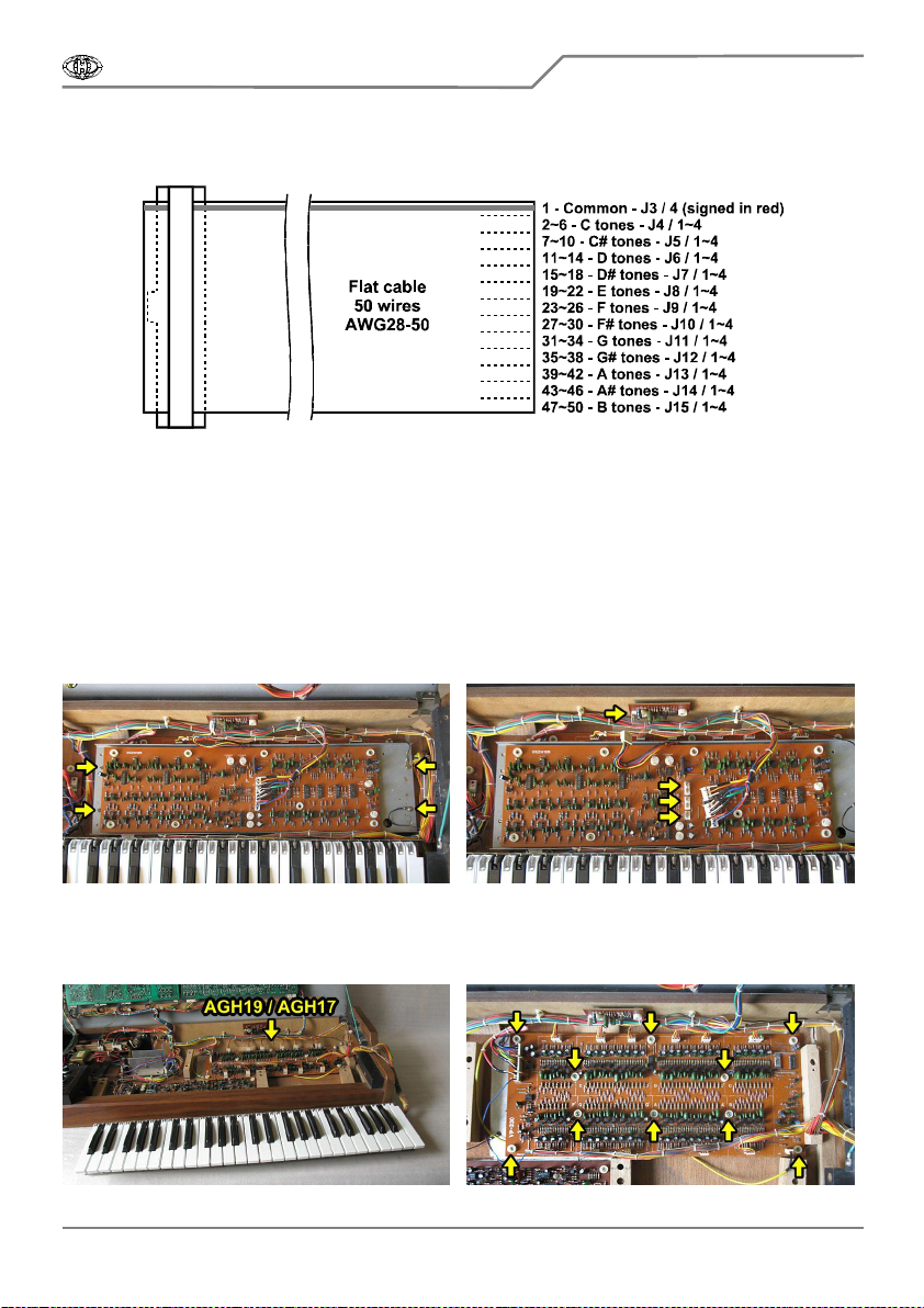
2.5. MONTAGE OF FLAT CONTROL SIGNALS CABLE
Control signals cable is equipped with flat 50-pin connector on one end (pic. 2.5.1). Wires
outgoing from this connector must be connected to several points of the AGH19 (AGH17 in older
VP330-KBD
Roland VP-330 MIDI Interface
Model 8-440 ver. 1.0
Copyright © 2015 CHD Elektroservis. All rights reserved.
No part of this publication may be reproduced in any form without the written permission of CHD Elektroservis.
9
model) printed circuit board of the instrument as shown on pic. 2.1.3. Individual wires of control signals
cable will be connected in accordance with table 1 and pic. 2.5.1.
Pic. 2.5.1
Split up free end of the cable (by ripping or cutting) to individual groups of wires and adjust their
lengths as necessary during the cable installation. Then stripe ends of the wires in length about 2 mm
and tin them. Note that wire Nr. 1 (terminal) is signed with red color.
a) First, FLH16 board must be removed in order to access to AGH19 (AGH17 in older model)
board: Unscrew four self tapping screws from metal holder of FLH16 board (pic. 2.5.2). Keep the
screws. They will be used again after the cable installation.
b) Unplug one connector from the little board on rear panel of instrument and three connectors
from the FLH16 board (pic. 2.5.3) – mark each of the connectors before, so that they are not swapped
when reassembling. Then pull off the holder with FLH16 board out of the instrument.
Pic. 2.5.2 Pic. 2.5.3
c) Lift the keyboard and slide it out of the instrument (pic. 2.5.4). The keyboard is detached
already. The main oscillator board AGH19 / AGH17 is now accessible.
Pic. 2.5.4 Pic. 2.5.5
VP330-KBD
Roland VP-330 MIDI Interface
Model 8-440 ver. 1.0
Copyright © 2015 CHD Elektroservis. All rights reserved.
No part of this publication may be reproduced in any form without the written permission of CHD Elektroservis.
10
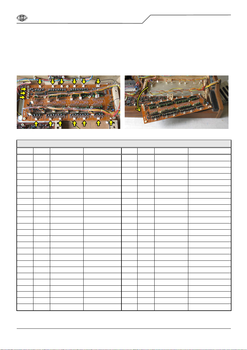
d) Unscrew ten screws from AGH19 board (pic. 2.5.5). Keep the screws. They will be used again
after the cable installation.
e) Unplug all sixteen connectors J1 to J16 from AGH19 / AGH17 board (pic. 2.5.6).
f) Remove the AGH19 / AGH17 board from the instrument (pic. 2.5.7) and put it solder side up.
Be careful during this and all next operations - note that electrostatic sensitive components are on
the board. Use conductive pad on the desktop and follow the rules for working with CMOS circuits!
Pic. 2.5.6 Pic. 2.5.7
Table 1 – Wires of flat cable of control signals connection
Wire Tone Connector / Pin Remark Wire Tone Connector / Pin Remark
1 Comm J3 / 4 Signed in red 26 F16 J9 / 4
2 C1 J4 / 1+2 To highest tone 27 F#2 J10 / 1
3 C2 J4 / 3 28 F#4 J10 / 2
4 C4 J4 / 4 29 F#8 J10 / 3
5 C8 J4 / 5 30 F#16 J10 / 4
6 C16 J4 / 6 To lowest tone 31 G2 J11 / 1
7 C#2 J5 / 1 32 G4 J11 / 2
8 C#4 J5 / 2 33 G8 J11 / 3
9 C#8 J5 / 3 34 G16 J11 / 4
10 C#16 J5 / 4 35 G#2 J12 / 1
11 D2 J6 / 1 36 G#4 J12 / 2
12 D4 J6 / 2 37 G#8 J12 / 3
13 D8 J6 / 3 38 G#16 J12 / 4
14 D16 J6 / 4 39 A2 J13 / 1
15 D#2 J7 / 1 40 A4 J13 / 2
16 D#4 J7 / 2 41 A8 J13 / 3
17 D#8 J7 / 3 42 A16 J13 / 4
18 D#16 J7 / 4 43 A#2 J14 / 1
19 E2 J8 / 1 44 A#4 J14 / 2
20 E4 J8 / 2 45 A#8 J14 / 3
21 E8 J8 / 3 46 A#16 J14 / 4
22 E16 J8 / 4 47 H2 J15 / 1
23 F2 J9 / 1 48 H4 J15 / 2
24 F4 J9 / 2 49 H8 J15 / 3
25 F8 J9 / 3 50 H16 J15 / 4

VP330-KBD
Roland VP-330 MIDI Interface
Model 8-440 ver. 1.0
Copyright © 2015 CHD Elektroservis. All rights reserved.
No part of this publication may be reproduced in any form without the written permission of CHD Elektroservis.
11
g) Now, it is necessary to solder particular wires of flat control signals cable to certain pads on
AGH19 / AGH17 board (pic. 2.5.8 and table 1). Note that wire Nr. 2 (tone C1) can be soldered to any
of pads Nr. 1 and 2 of J4. As mentioned above, length of particular groups of wires of flat cable should
be adjusted as required (pic. 2.5.9).
Pic. 2.5.8
h) After soldering all the wiring, the board should look like on pic. 2.5.9.
Pic. 2.5.9
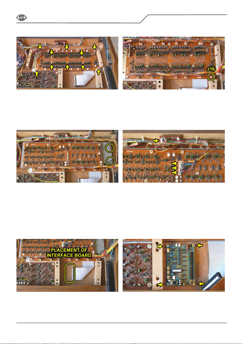
i) Return the AGH19 / AGH17 board to the original position and fix it back to bottom plate of the
instrument with ten original screws (pic. 2.5.10).
j) Plug fifteen connectors J1 to J15 of bunched cables back to the board. Do not plug J16
connector of shielded cable yet (pic. 2.5.11)!.
VP330-KBD
Roland VP-330 MIDI Interface
Model 8-440 ver. 1.0
Copyright © 2015 CHD Elektroservis. All rights reserved.
No part of this publication may be reproduced in any form without the written permission of CHD Elektroservis.
12
Pic. 2.5.10 Pic. 2.5.11
j) Put metal holder with FLH16 board back to the instrument and fix it with four original screws.
Don’t forget to insert two grounding lugs under the screws on right side (pic. 2.5.12)!
k) Plug three connectors of original bunched cables back to the FLH16 board and one connector
to the little board on the rear panel of the instrument (pic. 2.5.13). Be sure that the connectors are not
swapped (they should be marked as mentioned before in paragraph b).
Pic. 2.5.12 Pic. 2.5.13
2.6. MONTAGE OF THE INTERFACE BOARD
The interface board will be placed on right side on bottom plate of the instrument – under the
instrument’s keyboard (pic. 2.6.1).
a) Put the interface’s board to bottom plate of the instrument so that flat 50-pin plug is pointed to
the right. Insert four plastic supports from the interface accessory under the board (pic. 2.6.2).
Pic. 2.6.1 Pic. 2.6.2
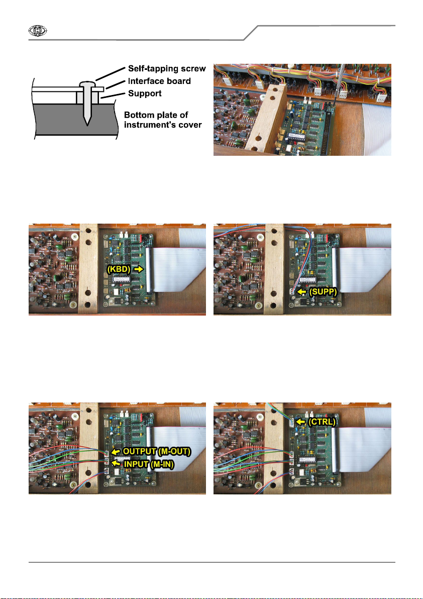
b) Fix the interface board in the bottom plate of the instrument using four self tapping screws
from the interface accessory (pic. 2.6.3). Make small holes for the screws with small drill or a peak
before (pic. 2.6.4).
VP330-KBD
Roland VP-330 MIDI Interface
Model 8-440 ver. 1.0
Copyright © 2015 CHD Elektroservis. All rights reserved.
No part of this publication may be reproduced in any form without the written permission of CHD Elektroservis.
13
Pic. 2.6.3 Pic. 2.6.4
c) Plug 50-pin connector of flat control signals cable to the interface board (KBD). The right
orientation of the connector is given by lock on the connector body (pic. 2.6.5).
d) Plug 3-pin connector of power supply bunched cables to the interface board (SUPP). The right
orientation of the connector is given by lock on the connector body (pic. 2.6.6).
Pic. 2.6.5 Pic. 2.6.6
e) Plug two 3-pin connectors of MIDI sockets to the interface board (M-IN, M-OUT). The right
orientation of the connectors is given by lock on the connector body (pic. 2.6.7). Be sure that MIDI
input and output sockets are not exchanged! If MIDI out socket had not been installed, see chapter 3.
f) Plug 4-pin connector of switch / LED bunched cables to the interface board (CTRL). The right
orientation of the connector is given by lock on the connector body (pic. 2.6.8). If control switch and
indication LED had not been installed, see chapter 3.
Pic. 2.6.7 Pic. 2.6.8
g) Plug 2-pin connector of shielded cable (originally leading to J16 on the main oscillator board
AGH19 / AGH17) to T-IN plug on the interface board (pic. 2.6.9).
h) Using shielded cable from the interface accessory, interconnect T-OUT plug on the interface
board with J16 plug on the main oscillator board (pic. 2.6.10).

VP330-KBD
Roland VP-330 MIDI Interface
Model 8-440 ver. 1.0
Copyright © 2015 CHD Elektroservis. All rights reserved.
No part of this publication may be reproduced in any form without the written permission of CHD Elektroservis.
14
Pic. 2.6.9 Pic. 2.6.10
i) Now, fix newly installed bunched cables leading from MIDI sockets and from power supply
board together with original shielded cable using four tightening plastic strips from the interface
accessory (pic. 2.6.11).
j) Put keyboard of the instrument back to original position in the instrument (pic. 2.6.12).
Pic. 2.6.11 Pic. 2.6.12
2.7. FINISHING OF THE INSTALLATION
Turn over the top panel of the instrument (close the instrument) and fix it with original six screws
to side plates (pic. 2.7.1). Fix the keyboard of the instrument to bottom plate of instrument’s cover with
five original screws (pic. 2.7.2). This is the reverse procedure of that described in the chapter 2.1.
Pic. 2.7.1 Pic. 2.7.2
Installation of the MIDI interface kit is now finished and the instrument is prepared for
communication via MIDI bus. After the interface activation, it controls keyboard and pitch shift circuits
of the instrument via MIDI commands accordingly to interface parameters settings. Enhanced functions
for control of the instrument via MIDI communication are described in detail in user manual of the
interface. So please read carefully user manual of the interface before use of the retrofitted
instrument to utilize the interface fully.

VP330-KBD
Roland VP-330 MIDI Interface
Model 8-440 ver. 1.0
Copyright © 2015 CHD Elektroservis. All rights reserved.
No part of this publication may be reproduced in any form without the written permission of CHD Elektroservis.
15
3. TIPS FOR INSTALLATION
Pic. 3.1
a) Output MIDI – THRU/OUT
The VP330-KBD Interface has both MIDI input and
output. However, only MIDI input is necessary unconditionally
for basic operation of the interface (i.e. controlling the
instrument via MIDI commands). MIDI THRU/OUT output
socket need not to be installed if you don’t require transfer of
MIDI data to another MIDI devices (THRU function) or reverse
communication of the interface with host system (OUT
function). It this case, connector CN2 (M-OUT) on the
interface board will remain unconnected (see pic. 3.1).
b) Switch and indication LED
Pic. 3.2
Installation of bunched cables of switch and indication
LED isn’t also necessary unconditionally. It is not needed to
install the bunched cables if you don’t want to affect the
instrument’s panel by drilling. However, jumper must be
plugged on pins Nr. 3 and 4 of CN3 (CTRL) connector on the
interface board in this case (see pic. 3.2).
It is also possible to install only indication LED on
instrument’s panel. In this case, remove (cut-off) switch from
bunched cables and connect (solder) together two black and
one blue wires leading to the switch originally and insulate the
connection of the wires (see pic. 3.3).
Pic. 3.3
In such “non-invasive” implementation the interface works following way: Immediately after the
instrument is switched on, the interface is activated but it still doesn’t affect the instrument – the
instrument can be used like without the interface. As soon as the first MIDI command is received at
interface’s MIDI input, the indication LED lights red and the interface starts to control the instrument’s
keyboard and pitch shift circuits. If you want to switch the interface off, so that it had no affect on the
instrument, the interface must be reset. It can be done by turning off and on the instrument or by MIDI
command “HW Reset” sent to the interface (see user manual of the interface).

7
This manual suits for next models
1
Table of contents
Other CHD Media Converter manuals


Popular Media Converter manuals by other brands


Crestron
Crestron HD-CONV-USB-300 quick start

Beijer Electronics
Beijer Electronics 100-0973 installation manual

Schumacher Electric
Schumacher Electric PID-500-USB owner's manual

Elko
Elko inels RFSG-1M quick start guide

Aurora Multimedia
Aurora Multimedia ASP-DTH user manual

Comtech EF Data
Comtech EF Data DT-4500 Series Installation and operation manual