CHD KM500-KBD User manual

KM500
KM500KM500
KM500-
--
-KBD
KBDKBD
KBD
MIDI Interface for
MIDI Interface forMIDI Interface for
MIDI Interface for
Korg M500 Micro
Korg M500 MicroKorg M500 Micro
Korg M500 Micro-
--
-Preset Keyboard
Preset KeyboardPreset Keyboard
Preset Keyboard
Model 8
Model 8Model 8
Model 8-
--
-428
428428
428
Version 1.0
Version 1.0Version 1.0
Version 1.0
Service Guide
Service GuideService Guide
Service Guide
© 2019 CHD Elektroservis
© 2019 CHD Elektroservis© 2019 CHD Elektroservis
© 2019 CHD Elektroservis
Korg M500 Interface
Korg M500 InterfaceKorg M500 Interface
Korg M500 Interface
KM500
KM500 KM500
KM500-
--
-KBD
KBD KBD
KBD Service Manual
Service ManualService Manual
Service Manual
8
88
8-
--
-428 / v. 1.00
428 / v. 1.00428 / v. 1.00
428 / v. 1.00
Copyright © 2019 CHD Elektroservis. All rights reserved.
No part of this publication may be reproduced in any form without the written permission of CHD Elektroservis.
2
2
2
2
1
11
1
INTRODUCTION
INTRODUCTIONINTRODUCTION
INTRODUCTION
The KM500-KBD interface includes EEPROM type memory for storing of basic firmware data. Necessary data are
programmed to the memory during the interface manufacturing so you need not to reload the data when the
you need not to reload the data when the you need not to reload the data when the
you need not to reload the data when the
new interface is being installed
new interface is being installednew interface is being installed
new interface is being installed. Only when the content of the memory is damaged or when interface’s CPU is
upgraded, you have to load the data to the memory again.
If the memory content is unreadable for the interface’s CPU (it is damaged or it is of different version), the
interface doesn’t work and it indicates fatal error status – indication LED of the interface blinks in yellow
continuously. In that case, execute procedure described in chapter 2.
If the interface’s CPU was replaced with another one with higher software version, it is recommended to adjust
the interface as described in chapter 3.
2
22
2
FIRMWARE DATA LOADING
FIRMWARE DATA LOADINGFIRMWARE DATA LOADING
FIRMWARE DATA LOADING
2.1
2.12.1
2.1
PREPARE THE INTERFACE (INSTRUMENT)
PREPARE THE INTERFACE (INSTRUMENT)PREPARE THE INTERFACE (INSTRUMENT)
PREPARE THE INTERFACE (INSTRUMENT)
Figure 1
Figure 1Figure 1
Figure 1
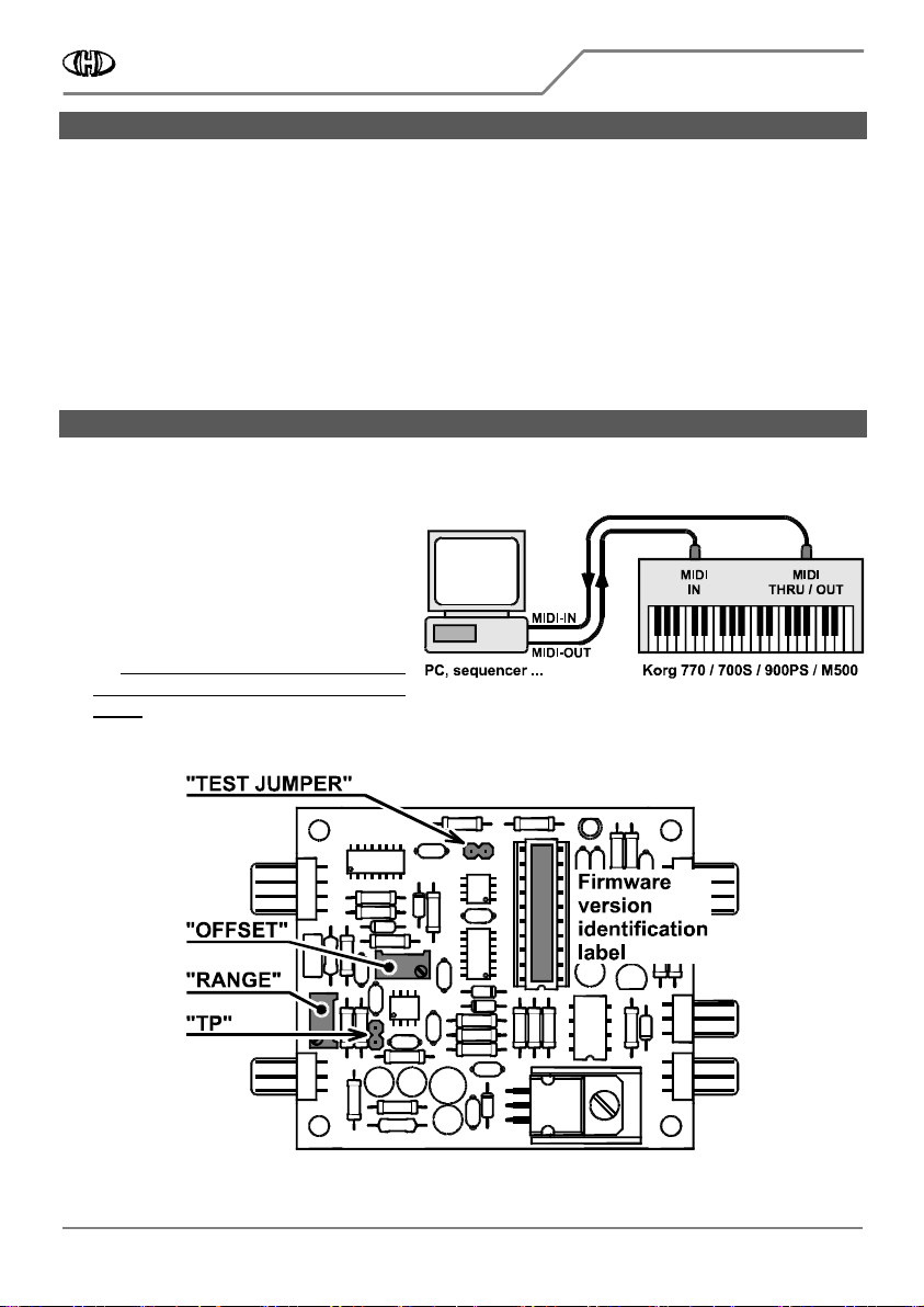
1. Interconnect the interface with your DAW /
PC bi-directionally (with both MIDI cables –
fig. 1).
2. Insert a jumper to the "TEST" plug head on
the interface board (fig. 2).
3. Plug instrument's power supply cable to a
mains socket and switch the instrument
on. Attention
Attention Attention
Attention -
--
- work very caref
work very caref work very caref
work very carefully during all
ully during all ully during all
ully during all
next procedures
next procedures next procedures
next procedures -
--
- there is a risk of electric
there is a risk of electric there is a risk of electric
there is a risk of electric
shock!
shock!shock!
shock!
Figure 2
Figure 2Figure 2
Figure 2

Korg M500 Interface
Korg M500 InterfaceKorg M500 Interface
Korg M500 Interface
KM500
KM500 KM500
KM500-
--
-KBD
KBD KBD
KBD Service Manual
Service ManualService Manual
Service Manual
8
88
8-
--
-428 / v. 1.00
428 / v. 1.00428 / v. 1.00
428 / v. 1.00
Copyright © 2019 CHD Elektroservis. All rights reserved.
No part of this publication may be reproduced in any form without the written permission of CHD Elektroservis.
3
3
3
3
2.2
2.22.2
2.2
CHECK FIRMWARE VERSION OF YOUR INTERFACE
CHECK FIRMWARE VERSION OF YOUR INTERFACECHECK FIRMWARE VERSION OF YOUR INTERFACE
CHECK FIRMWARE VERSION OF YOUR INTERFACE
Actual firmware version is written on label on the interface’s CPU (see fig. 2). If the label is missing or
unreadable, it is necessary ro read the actual version number from the CPU. This is feasible via MIDI SysEx
communication.
1. Enable SysEx messages record / monitoring on your DAW / PC.
Send “SW Version Request” (i.e. [
F0 00 20 21 7F 44 50 04 00 68 F7 hex
]) SysEx message from your DAW /
PC to the interface.
2. Red LED on the interface board blinks.
3.
The interface responds immediately by “SW Version Response” SysEx message. Form of the message is:
[F0
00 20 21 7F 44 50 04 vv xx F7 hex] where the [vv] byte is the version number (e.g. [10 hex] byte represents
version "1.0", [20 hex] byte represents version "2.0", etc.).
2.3
2.32.3
2.3
LOAD THE DATA
LOAD THE DATALOAD THE DATA
LOAD THE DATA
1. Open necessary MIDI file (according to version number previously read) with the basic firmware data in
your DAW / PC. You can find the archive with required MIDI files on our web site www.chd
www.chdwww.chd
www.chd-
--
-el.cz
el.czel.cz
el.cz.
2. Replay the MIDI file from your DAW / PC to the interface.
3. Red LED on the interface board blinks fast during the data transfer.
4. After the data are transferred, both indication LED and red LED on the interface board go off.
2.4
2.42.4
2.4
EXIT THE DATA LOADING
EXIT THE DATA LOADINGEXIT THE DATA LOADING
EXIT THE DATA LOADING
Switch the instrument off and remove the “TEST” jumper. Now you can end the uploading procedure or you can
continue to interface adjustment procedure.
• If you want to end, close the instrument. The next time you turn on the instrument, it will work with new
firmware data.
• See next chapter for continue to adjustment procedure.
3
33
3
ADJUSTMENT PROCEDURE
ADJUSTMENT PROCEDUREADJUSTMENT PROCEDURE
ADJUSTMENT PROCEDURE
There are two variable resistors on the interface board labeled “OFFSET” and “RANGE” (fig. 2). They have to be
adjusted before the upgraded interface is used. Adjustment procedure is following:
1. Connect MIDI output of your MIDI master keyboard (or PC / sequencer / DAW) to MIDI input of the
interface
1
11
1
.
2. Connect “HIGH” audio output of the instrument to a tuner or to a frequency meter.
3. Set all controllers on the instrument’s panels to a clear sound without any modulation:
• PITCH knob Æ to 0
00
0 (middle position)
• VIBRATO switch Æ to OFF
OFFOFF
OFF (middle position)
• REPEAT switch Æ to OFF
OFFOFF
OFF (middle position)
• TONE rotary selector Æ to 4’
4’4’
4’ (second position from top)
• TONE switch selector Æ to WOOD
WOODWOOD
WOOD (i.e. FLUTE tone is selected)
• PORTAMENTO switch Æ to OFF
OFFOFF
OFF (middle position)
Positions of all other controllers on instrument’s panel are not significant.
1
Set transmit MIDI Channel to number 1 on the master keyboard.
Korg M500 Interface
Korg M500 InterfaceKorg M500 Interface
Korg M500 Interface
KM500
KM500 KM500
KM500-
--
-KBD
KBD KBD
KBD Service Manual
Service ManualService Manual
Service Manual
8
88
8-
--
-428 / v. 1.00
428 / v. 1.00428 / v. 1.00
428 / v. 1.00
Copyright © 2019 CHD Elektroservis. All rights reserved.
No part of this publication may be reproduced in any form without the written permission of CHD Elektroservis.
4
44
4
4. Switch the instrument on by main switch joined with the POWER/VOLUME knob and turn the knob fully
clockwise (to maximum).
5. Now, the interface is in "Stand-by" mode - the interface’s indication LED is off. If not, press the "RESET"
button of the interface
2
22
2
.
6. Wait a few minutes
Wait a few minutesWait a few minutes
Wait a few minutes to stabilize the temperature of all instrument circuits.
7. Measure the voltage between pins of the "TP" jumper head (fig. 2) with a quality digital multimeter. It
should be zero volts exactly. If it is not, adjust it with "OFFSET” variable resistor (fig. 2).
Figure
Figure Figure
Figure 3
33
3
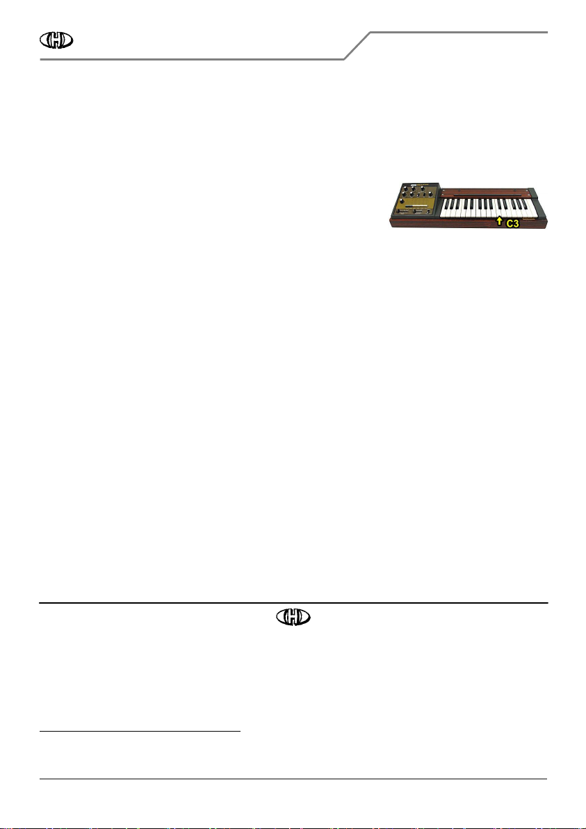
8. Press the C3 key on the instrument’s keyboard (fig. 3) – the
interface’s indication bi-color LED remains off.
9. Measure the output tone frequency by the tuner (frequency meter).
It should be 1047 Hz approx. Remember the measured tone
frequency. Then release the C3 key.
10. Press the C3 key on the master keyboard (i.e. send MIDI Note Nr. 84 to the interface) and hold it. The
interface’s indication LED will light in green.
11. Check the output tone frequency by the tuner (frequency meter) again. It must be the same as the
frequency measured in paragraph 9. If it is not, adjust it with "RANGE” variable resistor on the interface
board (fig. 2.9.1).
12. Release the C3 key on the master keyboard. Switch the instrument off and close the instrument.
KORG M500 MIDI Interface
Model KM500-KBD, Nr. 8-428, ver. 1.00
Document: 842810_service
Manufacturer: CHD Elektroservis, Czech Republic
www.chd-el.cz info@chd-el.cz
2
It is suppossed that the interface is in "Factory Reset" status before the adjustment procedure. If it is not, send the F0 0 0 20 21 7F 54 50 03 7F 5A
F0 00 20 21 7F 54 50 03 7F 5A F0 00 20 21 7F 54 50 03 7F 5A
F0 00 20 21 7F 54 50 03 7F 5A
F7 [hex]
F7 [hex]F7 [hex]
F7 [hex] SysEx message to the intarface first.
Table of contents
Other CHD Media Converter manuals


Popular Media Converter manuals by other brands


H&B
H&B TX-100 Installation and instruction manual

Bolin Technology
Bolin Technology D Series user manual

IFM Electronic
IFM Electronic Efector 400 RN30 Series Device manual

GRASS VALLEY
GRASS VALLEY KUDOSPRO ULC2000 user manual

Linear Technology
Linear Technology DC1523A Demo Manual

Lika
Lika ROTAPULS I28 Series quick start guide

Weidmuller
Weidmuller IE-MC-VL Series Hardware installation guide

Optical Systems Design
Optical Systems Design OSD2139 Series Operator's manual

Tema Telecomunicazioni
Tema Telecomunicazioni AD615/S product manual

KTI Networks
KTI Networks KGC-352 Series installation guide

Gira
Gira 0588 Series operating instructions

Lika
Lika SFA-5000-FD user guide