CHD VS-MIDI User manual

7
Model 8-434
ver. 1.0
INSTALLATION MANUAL
© 2009 CHD Elektroserv is

VS-MIDI
MIDI Interface for Vermona Synthesizer
Model 8-434 ver. 1.0
Copyri ght © 2009 CHD Elektroservis
All rights reserved. No part of this publication may be reproduc ed i n any form wi thout the written permission of CHD Elektroservis.
2
Content
1. Introduction . . . . . . . . . . . . . . . . . . . . . . . . . . . . . . . . . . . . . . . 3
1.1. Parts of MIDI interface kit . . . . . . . . . . . . . . . . . . . . . . . . . . . . . . . . 3
1.2. General information . . . . . . . . . . . . . . . . . . . . . . . . . . . . . . . . . . . 3
2. MIDI interface installation . . . . . . . . . . . . . . . . . . . . . . . . . . . . . . . . 4
2.1. Releasing of the instrument cover . . . . . . . . . . . . . . . . . . . . . . . . . . . . 4
2.2. MIDI connectors montage . . . . . . . . . . . . . . . . . . . . . . . . . . . . . . . . 5
2.3. Montage of supply bunched cables . . . . . . . . . . . . . . . . . . . . . . . . . . . 7
2.4. LED indicator montage . . . . . . . . . . . . . . . . . . . . . . . . . . . . . . . . . 8
2.5. Montage of signal bunched cables . . . . . . . . . . . . . . . . . . . . . . . . . . . 9
2.6. Interface board placement . . . . . . . . . . . . . . . . . . . . . . . . . . . . . . . . 12
2.7. Assembling of interface . . . . . . . . . . . . . . . . . . . . . . . . . . . . . . . . . 13
2.8. Finishing of installation . . . . . . . . . . . . . . . . . . . . . . . . . . . . . . . . . 14
3. Changes and new functions . . . . . . . . . . . . . . . . . . . . . . . . . . . . . . . 15
4. Limitations of instrument usage . . . . . . . . . . . . . . . . . . . . . . . . . . . . . 15
5. DAC-VCO calibration . . . . . . . . . . . . . . . . . . . . . . . . . . . . . . . . . . 15
Manufacturer :
CHD Elektroservis
Nad kundratkou 27, 19000 Praha 9
Czech Republic
info@chd-el.cz
www.chd-el.cz

VS-MIDI
MIDI Interface for Vermona Synthesizer
Model 8-434 ver. 1.0
Copyri ght © 2009 CHD Elektroservis
All rights reserved. No part of this publication may be reproduc ed i n any form wi thout the written permission of CHD Elektroservis.
3
1. INTRODUCTION
VS-MIDI is a MIDI retrofit for the Vermona Synthesizer. The device enables the instrument to
be controlled via MIDI as a MIDI expander. VS-MIDI controls VCO, VCF, VCA and EG of the
instrument.
1.1. PARTS OF MIDI INTERFACE KIT
The supplied MIDI interface kit contains all necessary parts, materials, and detailed installation
instructions.
Pic. 1-1 – Parts of interface kit
The kit contents:
1. MIDI Interface board
2. Supply bunched cables with
connector and LED
3. Signal bunched cables with
connector
4. 2x connector DIN-5 with cable
(including screws etc.)
5. CD-ROM with the user and
installation manuals and
software
1.2. GENERAL INFORMATION
The installation of all interface components is easy. If you follow the instruction from this manual
there will be no major problems during the installation procedure. All original features of Vermona
Synthesizer instrument are kept. The instrument can be used the same way as before the retrofitting.
The following tools are necessary for the installation: screwdriver, Phillips screwdriver, driller,
drills 3,2 a 16 mm, smaller rasp, soldering iron (a low heat iron and soldering paste).
Attention ! Disconnect the Vermona instrument form the mains prior to the installation.
Otherwise, there is a risk of the electric shock!
The producer is not responsible for any eventual mechanical or electrical damage of
the Vermona instrument caused by the infringement of the described installation
procedure or by careless manipulation during the installation of the MIDI interface!
VS-MIDI
MIDI Interface for Vermona Synthesizer
Model 8-434 ver. 1.0
Copyri ght © 2009 CHD Elektroservis
All rights reserved. No part of this publication may be reproduc ed i n any form wi thout the written permission of CHD Elektroservis.
4
2. MIDI INTERFACE INSTALLATION
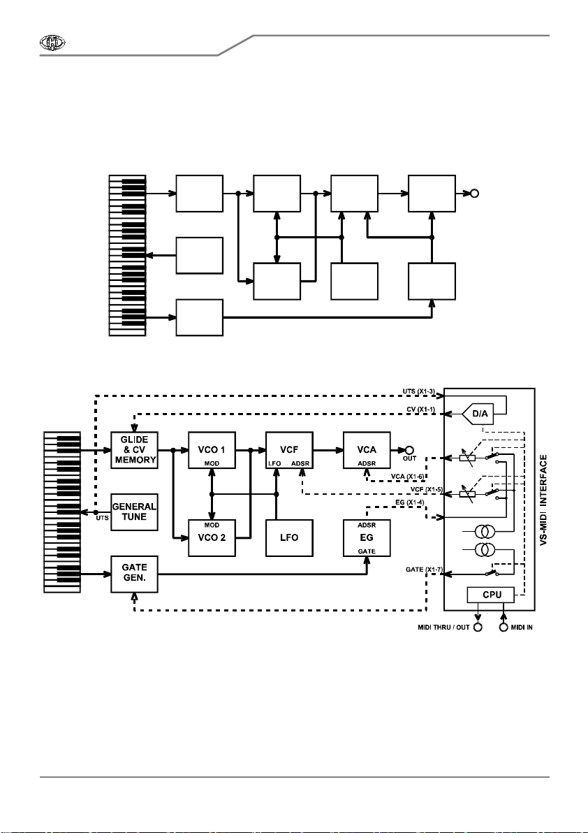
The interface takes control over some circuits of Vermona instrument - VCO, EG, VCF and VCA.
The following diagrams explain electrical connection of the instrument before (pic. 2-1) and after (pic.
2-2) the interface installation.
Pic. 2-1 – Original block schematics of the instrument
GLIDE
& CV
MEMORY
GATE
GEN.
VCO 1
VCO 2
VCF VCA
LFO EG
GENERAL
TUNE
MOD
MOD
ADSRLFO
GATE
ADSR
ADSR OUT
UTS
Pic. 2-2 – Connection of interface to the instrument
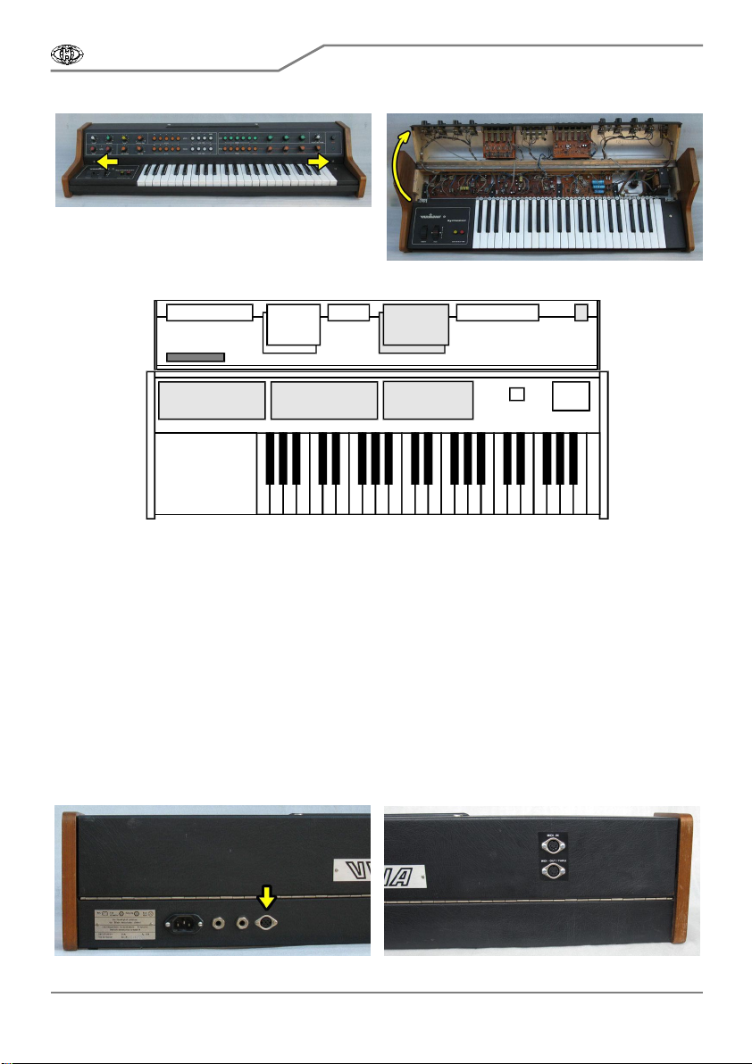
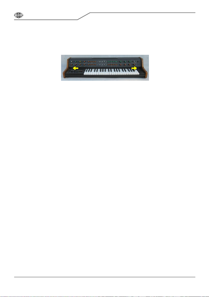
2.1. RELEASING OF THE INSTRUMENT COVER
a) Unscrew the two screws from the front panel of the instrument (pic. 2.1-1). Do not lose the
screws. They will be used again after the MIDI kit installation.
b) Carefully lift off instrument’s cover (pic. 2.1-2). Now, all instrument’s boards needed for the
interface installation are accessible – see pic. 2.1-3.
VS-MIDI
MIDI Interface for Vermona Synthesizer
Model 8-434 ver. 1.0
Copyri ght © 2009 CHD Elektroservis
All rights reserved. No part of this publication may be reproduc ed i n any form wi thout the written permission of CHD Elektroservis.
5
Pic. 2.1-1 Pic. 2.1-2
Pic. 2.1-3
VCO VCA POWER
SUPPLY
SWITCH
+ LED
VCF
EG
INTERFACE
2.2. MIDI CONNECTORS MONTAGE
Interface has both MIDI input and output. Only MIDI input is necessary for the interface operation,
MIDI output need not to be installed - podle požadavků uživatele. Na volbě uživatele také závisí
method of MIDI-IN and M IDI-OUT connectors montage. Couple of facilities is here:
If you do not want to mechanically damage panel of the instrument, install only MIDI-IN connector –
replace headphones socket obn rear panel with MIDI-IN socket. MIDI output stays unconnected in
that case (see pic. 2.2-1).
If you want to keep headphones connector operational and instrument’s panel without additional
holes, MIDI cables can be pulled out of the instrument through a slot between instrument’s cover
parts.
The best is to use both MIDI-IN and MIDI-OUT/THRU connectors for easy connection of MIDI
system and to place the connectors onto rear panel of instrument (see pic. 2.2-2). In that case, it is
necessary to drill holes for connector to instrument’s panel.
Pic. 2.2-1 Pic. 2.2-2

VS-MIDI
MIDI Interface for Vermona Synthesizer
Model 8-434 ver. 1.0
Copyri ght © 2009 CHD Elektroservis
All rights reserved. No part of this publication may be reproduc ed i n any form wi thout the written permission of CHD Elektroservis.
6
The MIDI connectors installation procedure is then as follows:
a) Flip the cover over and return it to its original closed position on top of the instrument.
b) Drill two holes with diameter 16 mm and four holes with diameter 3,2 mm to left side of rear
panel of the instrument as shown on pic. 2.2-3. Work carefully so as to not drill the parts and
components inside the instrument (pic. 2.2-4).
Pic. 2.2-3 Pic. 2.2-4
1
6
0
22,5
3230
c) Clean the edge of the holes with small rasp. Also clean the holes from the inside after the
turning over the front cover.
d) Clean all metal sawdust and raspings from the inside of the instruments, they can cause
short circuits or serious electrical damage if left in the instrument. Please clean the instrument
carefully!
e) Get flat connectors of MIDI cables through the holes in rear panel into the instrument (pic. 2.2-
5). Both cables are the same and they can be exchanged.
f) Insert the DIN connectors into hole in rear panel (pic. 2.2-6) and fix the connectors to the panel
using screws, washers and nuts (pic. 2.2-7).
Pic. 2.2-5 Pic. 2.2-6

VS-MIDI
MIDI Interface for Vermona Synthesizer
Model 8-434 ver. 1.0
Copyri ght © 2009 CHD Elektroservis
All rights reserved. No part of this publication may be reproduc ed i n any form wi thout the written permission of CHD Elektroservis.
7
Pic. 2.2-7
g) You may also want to label the connectors
("MIDI IN", "MIDI THRU/OUT") using self-adhesive, for
example (see pic. 2.2-2).
2.3. MONTAGE OF SUPPLY BUNCHED CABLES
Supply bunched cables is equipped with flat five-pin connector. Four wires of bunched cables (Nr.
2 to 5) must be connected to instrument’s power supply board as displayed on pic. 2.3.-1. Used solder
lugs on power supply board shows pic. 2.3-2.
Pic. 2.3-1 – Connection of supply cable bundle and LED
X2
-12V
+12V
+20V
GND
(red LED)
(g
r
een LED)
-20V
GND
POWER SUPPLY
BOARD
5
4
3
2
1
blue
red
yellow
black
green
original parts
Pic. 2.3-2 – Solder lugs on power supply board
SCREW
WASHER
NUT
PANEL
DIN
SOC
K
ET
VS-MIDI
MIDI Interface for Vermona Synthesizer
Model 8-434 ver. 1.0
Copyri ght © 2009 CHD Elektroservis
All rights reserved. No part of this publication may be reproduc ed i n any form wi thout the written permission of CHD Elektroservis.
8
Pic. 2.3-3 – Placement of supply bunched cables
a) Put supply bunched cables to instrument’s cover – add them under glazing sprig to original
cables (pic. 2.3-3).
b) Solder the black cable Nr. 2 to ground potential – solder lug (2) GND (pic. 2.3-2).
c) Solder the yellow cable Nr. 3 to supply voltage +20V – solder lug (3) +20V. This lug is free by
that time, no next cable is connected to it (pic. 2.3-2).
d) Solder the red cable Nr. 4 to supply voltage +12V – solder lug (4) +12V (pic. 2.3-2).
e) Solder the blue cable Nr. 5 to supply voltage -12V – solder lug (5) -12V (pic. 2.3-2).
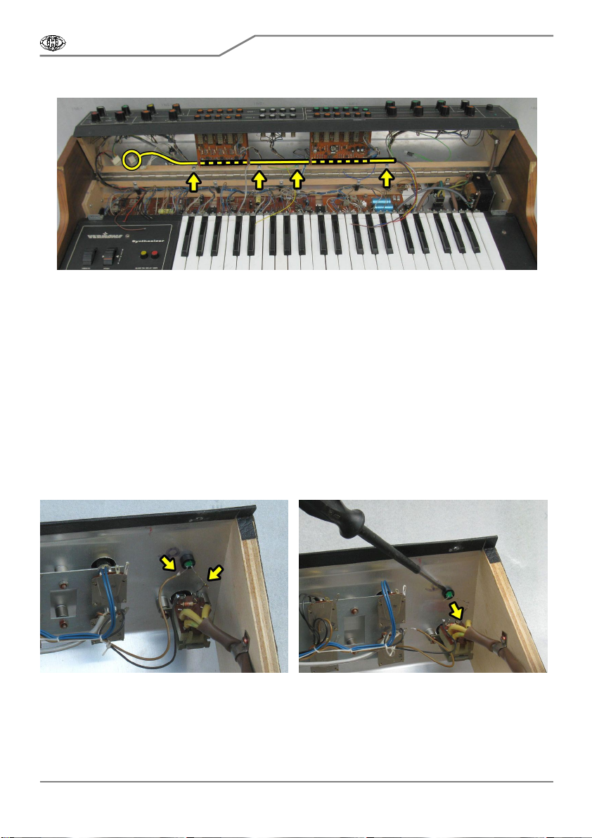
2.4. LED INDICATOR MONTAGE
Original LED which indicates power-on status of the instrument has to be replaced with two-color
LED. This LED is fixed to cable Nr. 1 of supply bunched cables. Procedure is as follows:
a) Unsolder leads of original LED (pic. 2.4-1).
b) Eject snap ring of LED holder with help of screwdriver for example (pic. 2.4-2).
Pic. 2.4-1 Pic. 2.4-2
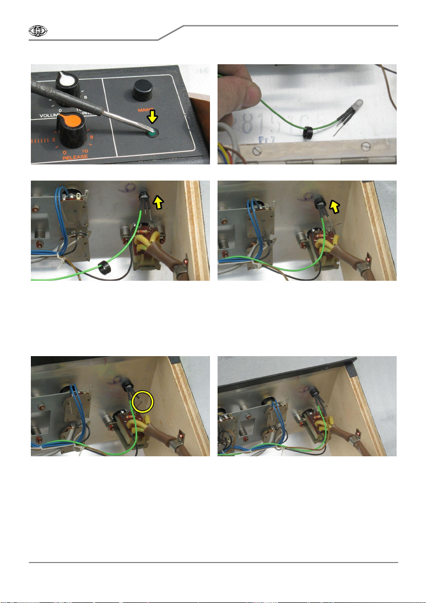
c) Remove LED from holder – push to its head from front side (pic. 2.4-3).
d) Plant snap ring of LED holder to new two-color LED (pic. 2.4-4).
e) Insert new LED into holder so that its free leads will be to right (pic. 2.4-5).
f) Assure new LED against its extrusion – clap snap ring back to LED holder (pic. 2.4-6).
VS-MIDI
MIDI Interface for Vermona Synthesizer
Model 8-434 ver. 1.0
Copyri ght © 2009 CHD Elektroservis
All rights reserved. No part of this publication may be reproduc ed i n any form wi thout the written permission of CHD Elektroservis.
9
Pic. 2.4-3 Obr. 2.4-4
Pic. 2.4-5 Pic. 2.4-6
g) Solder free outer lead of new LED to jumper wire brought from resistor fixed on switch (pic.
2.4-7).
h) Place a shrink-wrap insulation tube on brown cable (-20V) unsoldered from original LED and
solder the cable to middle lead of new LED. Isolate the connection with the insulation tube and heat it
until it shrinks tightly to the cable and LED’s lead (pic. 2.4-8). The tube can be heated with a hot-flue
pistol, for example.
Pic. 2.4-7 Pic. 2.4-8
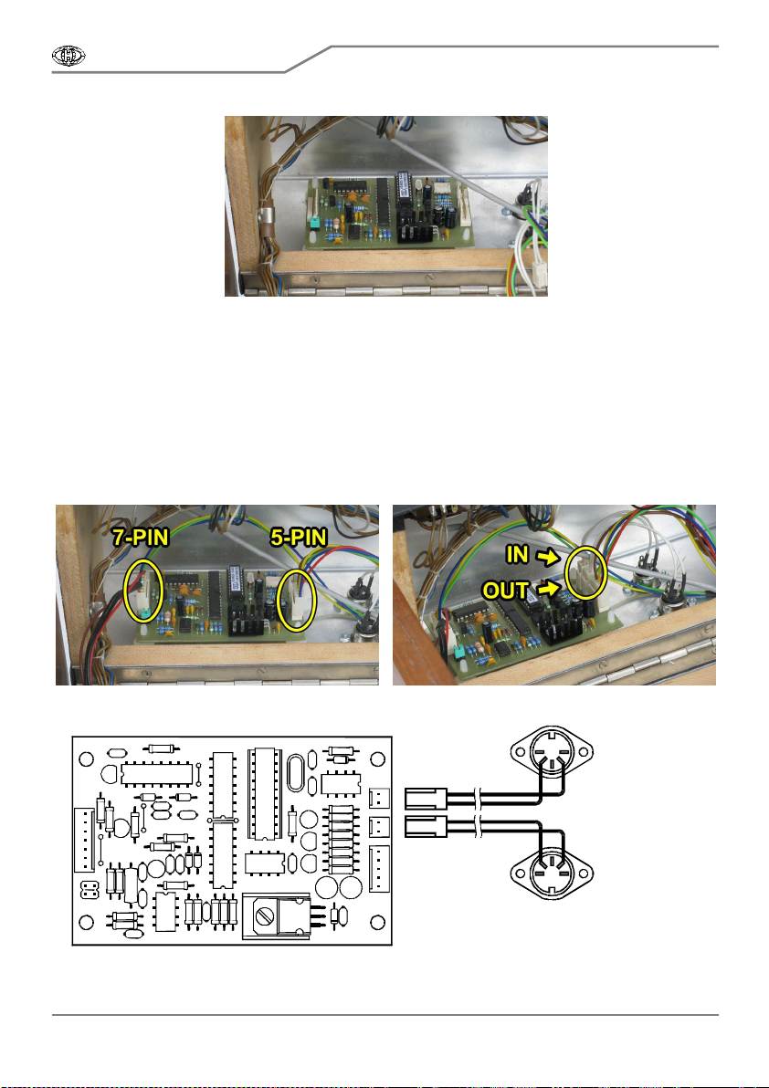
2.5. MONTAGE OF SIGNAL BUNCHED CABLES
Signal bunched cables is equipped with flat seven-pin connector. Wires of bunched cables must
be connected to instrument’s VCO, VCF, VCA a EG boards as displayed on pic. 2.5.-1. Used solder
lugs and pads on boards shows pictures 2.5-3 to 2.5-6.
a) Add bunched cables to original cables – use original glazing sprig. Blue, green and yellow
cables are in instrument’s cover; black, red, and shielded cables are directed to bottom basis part of
the instrument (pic. 2.5-2).

VS-MIDI
MIDI Interface for Vermona Synthesizer
Model 8-434 ver. 1.0
Copyri ght © 2009 CHD Elektroservis
All rights reserved. No part of this publication may be reproduc ed i n any form wi thout the written permission of CHD Elektroservis.
10
Pic. 2.5-1 – Connection of signal bunched cables
X1
1
2
3
4
5
6
7
UTS
EG
VCO, VCF, VC
A
, EG BO
A
R
DS
VCF
VCA
Gate red
yellow
green
blue
GND black
white
CV red
Pic. 2.5-2 – Placement of signal bunched cables
Pic. 2.5-3 – Solder lugs on VCO board

VS-MIDI
MIDI Interface for Vermona Synthesizer
Model 8-434 ver. 1.0
Copyri ght © 2009 CHD Elektroservis
All rights reserved. No part of this publication may be reproduc ed i n any form wi thout the written permission of CHD Elektroservis.
11
b) Solder shielded cable Nr. 1 (red – one wire of shielded twin-lead) to left lead of resistor R25
(near operational amp IS1) on VCO board – pad (1) CV.
c) Solder shielded cable Nr. 3 (white – the other wire of shielded twin-lead) to UTS signal on VCO
board – solder lug (3) UTS.
d) Solder the black cable Nr. 2 (ground + shielding) to ground potential on VCO board – solder
lug (2) GND.
e) Solder the red cable Nr. 7 to signal GATE on VCO board – solder lug (7) Gate.
Pic. 2.5-4 – Solder lugs on EG board
f) Unsolder two blue cables from solder lug ADRS on EG board (pic. 2.5-3) and solder blue cable
Nr. 4 (EG) of signal bunched cables to this lug.
Pic. 2.5-5 – Solder lugs on VCF board

VS-MIDI
MIDI Interface for Vermona Synthesizer
Model 8-434 ver. 1.0
Copyri ght © 2009 CHD Elektroservis
All rights reserved. No part of this publication may be reproduc ed i n any form wi thout the written permission of CHD Elektroservis.
12
g) Unsolder blue cable from solder lug ADRS on VCF board (pic. 2.5-4) and solder green cable
Nr. 5 (VCF) of signal bunched cables to this lug.
Pic. 2.5-6 – Solder lugs on VCA boar d
g) Unsolder blue cable from solder lug ADRS on VCA board (pic. 2.5-5) and solder yellow cable
Nr. 6 (VCA) of signal bunched cables to this lug.
h) Original blue cables (which related EG, VCF, VCA boards) can be fully removed or it can be
retained in the instrument, but it is necessary to insulate them in this case so that no short occurs in
the instrument.
2.6. INTERFACE BOARD PLACEMENT
a) Board of the interface will be placed left on rear panel, inside the instrument (pic. 2.6-1).
Cleanse and degrease this place fairly.
b) Remove protective foil form the self-adhesive supports of interface’s board (pic. 2.6-2).
Pic. 2.6-1 Pic. 2.6-2
c) Put interface’s board to rear panel of the instrument so that seven-pin connector is left (pic.
2.6-3) and then fix the self-adhesive supports by pressing down.
VS-MIDI
MIDI Interface for Vermona Synthesizer
Model 8-434 ver. 1.0
Copyri ght © 2009 CHD Elektroservis
All rights reserved. No part of this publication may be reproduc ed i n any form wi thout the written permission of CHD Elektroservis.
13
Pic. 2.6-3
2.7. ASSEMBLING OF INTERFACE
a) Put the seven-pin connector of signal bunched cables to plug left on the interface’s board.
Orientation of the connector is unambiguously given by the connector lock (pic. 2.7-1).
b) Put the five-pin connector of supply bunched cables to plug right on the interface’s board.
Orientation of the connector is unambiguously given by the connector lock (pic. 2.7-1).
c) Put two two-pin connectors of MIDI cables to plugs right on the interface’s board. Orientation
of the connectors is unambiguously given by the connectors locks. Be sure the connectors are not
exchanged. MIDI input must be put to plug X3 and MIDI output to plug X4 (see pic. 2.7-2 and 2.7-3).
Pic. 2.7-1 Pic. 2.7-2
Pic. 2.7-3
MIDI - IN
5(-)4(+)
4(+)5(-)
MIDI - THRU / OUT
X3
X4
2
1
2
1

VS-MIDI
MIDI Interface for Vermona Synthesizer
Model 8-434 ver. 1.0
Copyri ght © 2009 CHD Elektroservis
All rights reserved. No part of this publication may be reproduc ed i n any form wi thout the written permission of CHD Elektroservis.
14
d) Now, version of instrument’s VCO board must be identified and in dependence on it, jumper
on interface’s board must be set. Version of VCO board can be easily discovered pursuant type of
operational amp on IS1 position and pursuant values of resistors R24 and R25:
Pic. 2.7-4 – Detection of VCO board version
Older version of VCO board (1) has operational amp B081 (it has 8 leads) on position IS1 and
values of R24 and R25 resistors are 220kΩ. Newer version of VCO board (2) has operational amp
A109 (it has 14 leads) on position IS1 and values of R24 and R25 resistors are 22kΩ. Type of
operational amp is printed directly on its cover and values of the resistors can be measured with help
of a multimeter for example.
For older version of VCO board (IS1 = B081; R24, R25 = 220kΩ), plug jumper on interface board
to position (1). For newer version of VCO board (IS1 = A109; R24, R25 = 22kΩ), plug jumper on
interface board to position (2). See pic. 2.7-5.
Pic. 2.7-5 – Setting of jumper
1) Older version
2) Newer version
1
2
VS-MIDI
MIDI Interface for Vermona Synthesizer
Model 8-434 ver. 1.0
Copyri ght © 2009 CHD Elektroservis
All rights reserved. No part of this publication may be reproduc ed i n any form wi thout the written permission of CHD Elektroservis.
15
2.8. FINISHING OF INSTALLATION
a) Turn over the front panel of the instrument (close the instrument) and fix it with two screws.
This is the reverse procedure of that described in the chapter 2.1.
Pic. 2.8-1
Installation of the MIDI kit is now complete and Vermona Synthesizer is ready to communicate
over the MIDI. Please read carefully the user manual first.
3. CHANGES AND NEW FUNCTIONS
Vermona instrument works exactly the same way as before the interface installation if it isn’t
connected to MIDI system. The only change is in color of LED indicator on front panel. Power-on
status is indicated by red LED now LED (originally green LED).
Extending functions for control of VCO, VCF, VCA and EG circuits via MIDI communication are
described in user manual in detail.
4. LIMITATIONS OF INSTRUMENT USAGE
It isn’t possible to control instrument’s VCO from its own keyboard and via MIDI notes
simultaneously. If there are any MIDI commands – Note-On/Off received, the interface take over the
control of the VCO, VCF and VCA circuits of the instrument and the instrument’s own keyboard can
not be used yet! Instrument’s VCO is fully detuned in that case. If there is a request to use own
instrument’s keyboard again, reset the interface e.g. switch the instrument off, wait for a while and then
switch the Vermona Synthesizer on.
If “Pitch Bend” MIDI command is used for control, the pitch shift range of the VCO might be
limited upwards for the highest octave and the total pitch shift is limited to approx four tones. This
limitation is done by the construction of the Vermona Synthesizer and can’t be removed.
5. DAC-VCO CALIBRATION
If the exact tuning of the instrument keyboard and master MIDI keyboard is required, D/A
converter controlling VCO of the instrument must be calibrated. Range of calibration is ±100 cents,
calibration step is 1,5873 cent. Calibration procedure consists in change of system parameter “VCO
Calibration“ (calibration constant). It can be done with help of MIDI System Exclusive Messages.
Calibration constant is stored in internal interface’s memory so new value stays unchanged after the
instrument is switched off. Value of calibration constant is set to 64 (±0 cent, no shift) during
production.
7
Table of contents
Other CHD Media Converter manuals


Popular Media Converter manuals by other brands

Goldmund
Goldmund MIMESIS 20M user manual

Shinybow USA
Shinybow USA SB-6358 instruction manual

Konig
Konig CMP-USBVG5 manual

Connection Technology Systems
Connection Technology Systems CVT-100W2X user guide

Diamond Multimedia
Diamond Multimedia VC500 Troubleshooting

LED World
LED World HUEDA SR-2108B-24M-3 installation instructions


