CHD TR2-KBD Guide

7
Model 8-436
ver. 1.0
INSTALLATION MANUAL
Rev. 2
© 2018 CHD Elektroserv is

TR2-KBD
MIDI Interface for Korg Trident Keyboard
Model 8-436 ver. 1.0
Copyright © 2018 CHD Elektroservis.
All rights reserved. No part of this publication may be reproduced in any form without the written permission of CHD Elektroservis.
2
Contents page
1
11
1
INTR
INTRINTR
INTRODUCTION
ODUCTIONODUCTION
ODUCTION . . . . . . . . . . . . . . . . . . . . . . . . . . . . . . . . . . . . . . . . . . . . . . . . . . . . . . . . . . . . . . . . . .
. . . . . . . . . . . . . . . . . . . . . . . . . . . . . . . . . . . . . . . . . . . . . . . . . . . . . . . . . . . . . . . . . . . . . . . . . . . . . . . . . . . . . . . . . . . . . . . . . . . . . . . . . . . . . . . . . . . . . . . . . . . . . . . . . . . .
. . . . . . . . . . . . . . . . . . . . . . . . . . . . . . . . . . . . . . . . . . . . . . . . . . . . . . . . . . . . . . . . . .
3
33
3
1.1 MIDI INTERFACE KIT PARTS
MIDI INTERFACE KIT PARTSMIDI INTERFACE KIT PARTS
MIDI INTERFACE KIT PARTS . . . . . . . . . . . . . . . . . . . . . . . . . . . . . . . . . . . . . . . . . . . . . . . . . . . . . . . . 3
1.2 GENERAL INFORMATION . . . . . . . . . . . . . . . . . . . . . . . . . . . . . . . . . . . . . . . . . . . . . . . . . . . . . . . . . 3
2
22
2
INSTALLATION OF MIDI INTERFACE
INSTALLATION OF MIDI INTERFACEINSTALLATION OF MIDI INTERFACE
INSTALLATION OF MIDI INTERFACE . . . . . . . . . . . . . . . . . . . . . . . . . . . . . . . . . . . . . .
. . . . . . . . . . . . . . . . . . . . . . . . . . . . . . . . . . . . . . . . . . . . . . . . . . . . . . . . . . . . . . . . . . . . . . . . . . . .
. . . . . . . . . . . . . . . . . . . . . . . . . . . . . . . . . . . . . . . . . . . . . . . . .
. . . . . . . . . . . . . . . . . . . . . .
. . . . . . . . . . . .
. .
.
4
44
4
2.1 RELEASING OF THE INSTRUMENT COVER . . . . . . . . . . . . . . . . . . . . . . . . . . . . . . . . . . . . . . . . . . . . . 4
2.2 MIDI-IN SOCKET INSTALLATION . . . . . . . . . . . . . . . . . . . . . . . . . . . . . . . . . . . . . . . . . . . . . . . . . . . . . 5
2.3 FLAT CABLE MONTAGE . . . . . . . . . . . . . . . . . . . . . . . . . . . . . . . . . . . . . . . . . . . . . . . . . . . . . . . . . . . . 6
2.4 INTERFACE BOARD INSTALLATION . . . . . . . . . . . . . . . . . . . . . . . . . . . . . . . . . . . . . . . . . . . . . . . . . . 9
2.5 INSTRUMENT ASSEMBLY . . . . . . . . . . . . . . . . . . . . . . . . . . . . . . . . . . . . . . . . . . . . . . . . . . . . . . . . . . 11
TR2-KBD
MIDI Interface for Korg Trident Keyboard
Model 8-436 ver. 1.0
Copyright © 2018 CHD Elektroservis.
All rights reserved. No part of this publication may be reproduced in any form without the written permission of CHD Elektroservis.
3
1
11
1
INTR
INTRINTR
INTRODUCTION
ODUCTIONODUCTION
ODUCTION
Korg Trident / Trident Mk II Keyboard MIDI Interface enables the integration of MIDI in your Trident instrument.
The instrument's keyboard can be controlled with this MIDI interface in parallel manner. The interface only
receives MIDI data so it has MIDI input only.
1.1
1.11.1
1.1
MIDI INTERFACE KIT PARTS
MIDI INTERFACE KIT PARTSMIDI INTERFACE KIT PARTS
MIDI INTERFACE KIT PARTS
Pic. 1
Pic. 1 Pic. 1
Pic. 1 –
––
– Parts of MIDI interface
Parts of MIDI interface Parts of MIDI interface
Parts of MIDI interface kit
kit kit
kit
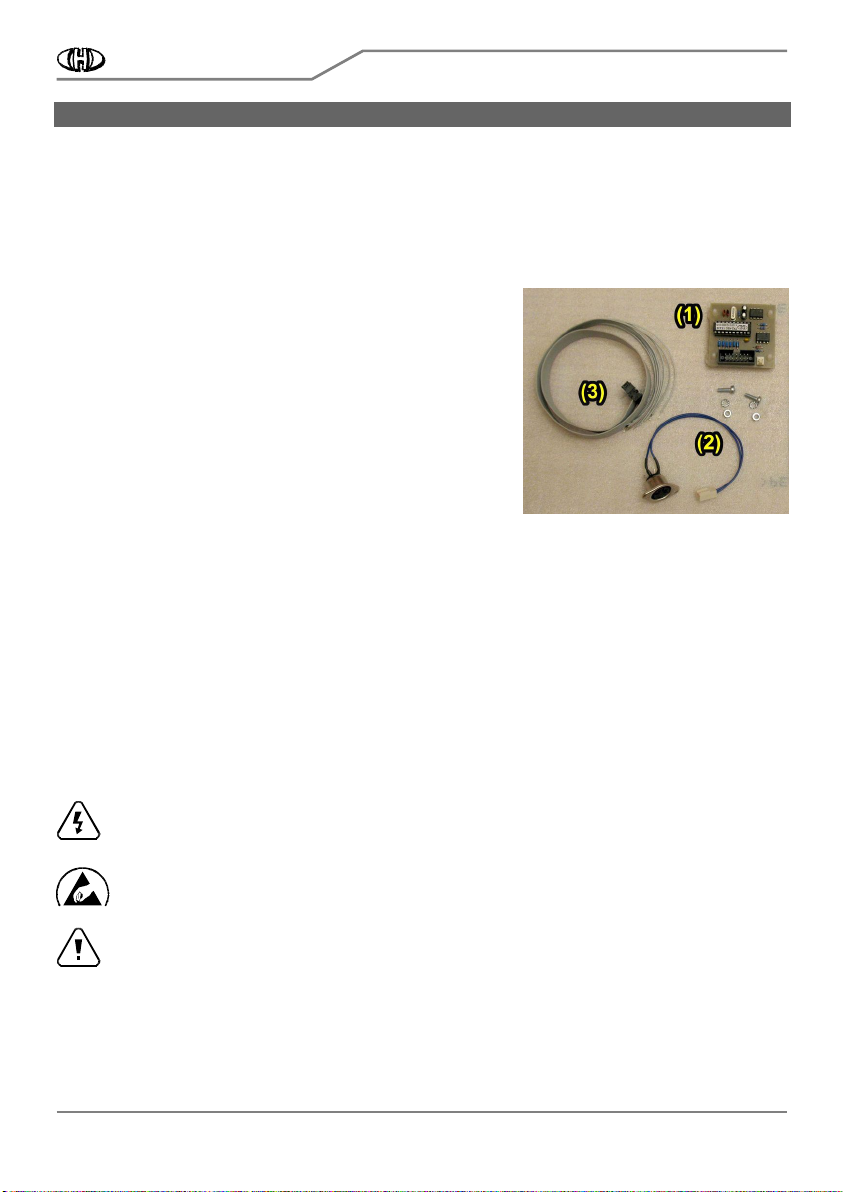
The supplied MIDI interface kit contains all necessary parts,
materials, and detailed installation instructions. The kit contents:
1. MIDI interface board with self-adhesive supports
2. MIDI connector with bunched cables and screws, nuts and
washers
3. 14-wire flat cable with connector
4. Owner’s and Installation manuals in PDF form
1.2
1.21.2
1.2
GENERAL INFORMATION
GENERAL INFORMATIONGENERAL INFORMATION
GENERAL INFORMATION
The installation of all interface components is very easy. If you follow the instruction from this manual there will
be no major problems during the installation procedure. The cover of the instrument will not be markedly
damaged during the installation. The physical appearance of the vintage instrument remains nearly the same as
before the installation. If necessary, the interface can be removed and the instrument restored back to original
appearance. All original features of the Korg Trident (Mk II) are kept. The instrument can be used the same way
as before the retrofitting.
The following tools are necessary for the installation: Phillips screwdriver, driller, drills 3,2 and 16 mm, smaller
rasp, pliers, soldering iron (a low heat iron and soldering paste).
Attention !
Attention !Attention !
Attention ! Disconnect the instrument form the mains prior to the installation. Otherwise, there is a
risk of the electric shock!
Attention!
Attention!Attention!
Attention! Observe precautions for handling electrostatic discharge sensitive devices!
Attention!
Attention!Attention!
Attention! The producer is not responsible for any eventual mechanical or electrical damage of the
instrument caused by the infringement of the described installation procedure or by careless
manipulation during the installation of the MIDI interface!

TR2-KBD
MIDI Interface for Korg Trident Keyboard
Model 8-436 ver. 1.0
Copyright © 2018 CHD Elektroservis.
All rights reserved. No part of this publication may be reproduced in any form without the written permission of CHD Elektroservis.
4
2
22
2
INSTALLATION OF MIDI INTERFACE
INSTALLATION OF MIDI INTERFACEINSTALLATION OF MIDI INTERFACE
INSTALLATION OF MIDI INTERFACE
The interface is connected to the keyboard switch matrix on “Key Assigner“ board of the instrument. Label of
this board is KLM-300 in Trident and KLM-377 in Trident Mk II. These boards are different only in details. The
interface is connected to both types of board by the same way.
Pic. 2
Pic. 2 Pic. 2
Pic. 2 –
––
– Connection of the interface
Connection of the interface Connection of the interface
Connection of the interface
2.1
2.12.1
2.1
RELEASING OF THE INSTRUMENT COVER
RELEASING OF THE INSTRUMENT COVERRELEASING OF THE INSTRUMENT COVER
RELEASING OF THE INSTRUMENT COVER
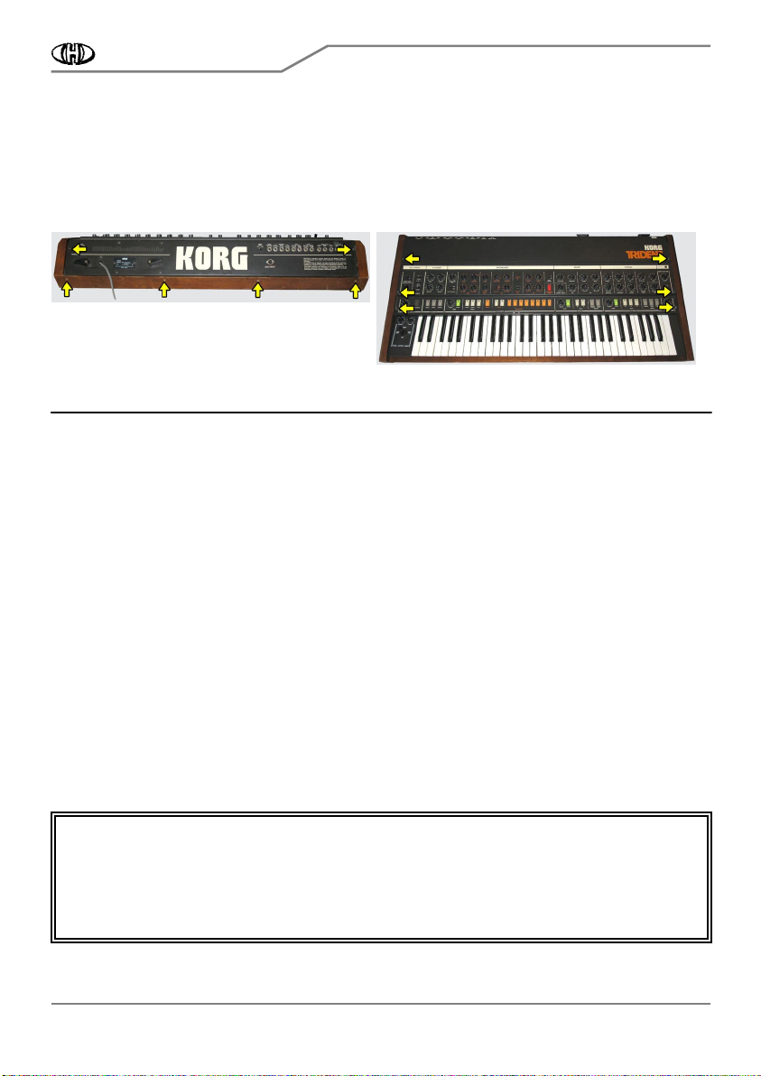
a) Unscrew the six screws from the top of the instrument (pic. 2.1-1) and the six screws on the rear panel (pic.
2.1-2). Do not lose the screws. They will be used again after the MIDI kit installation.
b) Carefully open the instrument - lift off the instrument’s panel (pic. 2.1-3).
Pic. 2.1
Pic. 2.1Pic. 2.1
Pic. 2.1-
--
-1
11
1
Pic. 2.1
Pic. 2.1 Pic. 2.1
Pic. 2.1-
--
-2
22
2
Pic. 2.1
Pic. 2.1Pic. 2.1
Pic. 2.1-
--
-3
33
3
TR2-KBD
MIDI Interface for Korg Trident Keyboard
Model 8-436 ver. 1.0
Copyright © 2018 CHD Elektroservis.
All rights reserved. No part of this publication may be reproduced in any form without the written permission of CHD Elektroservis.
5
2.2
2.22.2
2.2
MIDI
MIDIMIDI
MIDI-
--
-IN
IN IN
IN SOCKET
SOCKETSOCKET
SOCKET INSTALLATION
INSTALLATION INSTALLATION
INSTALLATION
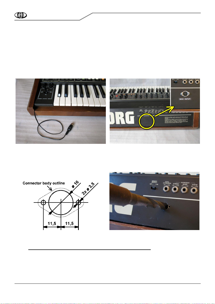
There are two possible ways to install the MIDI-IN DIN socket:
If you do not want to mechanically damage the rear panel of the instrument, take out the MIDI cable through
the slot on the left side of the keyboard and solder cable DIN connector on its end (see pic. 2.2-1).
It is better to place the MIDI-In connector on the rear panel of the instrument for easier operation. It is
necessary to drill three holes in the instrument panel however. The MIDI-In connector can be installed near
the jack connectors (see pic. 2.2-2). The MIDI-In connector installation procedure is as follows:
Pic. 2.2
Pic. 2.2Pic. 2.2
Pic. 2.2-
--
-1
11
1
Pic. 2.2
Pic. 2.2Pic. 2.2
Pic. 2.2-
--
-2
22
2
a) Flip the front cover over and return it to its original closed position on top of the synth.
b) Drill three holes in the rear panel as shown on pic. 2.2-3. Work carefully so as to not drill the parts inside the
instrument (pic. 2.2-4).
Pic. 2.2
Pic. 2.2Pic. 2.2
Pic. 2.2-
--
-3
33
3
Pic. 2.2
Pic. 2.2Pic. 2.2
Pic. 2.2-
--
-4
44
4
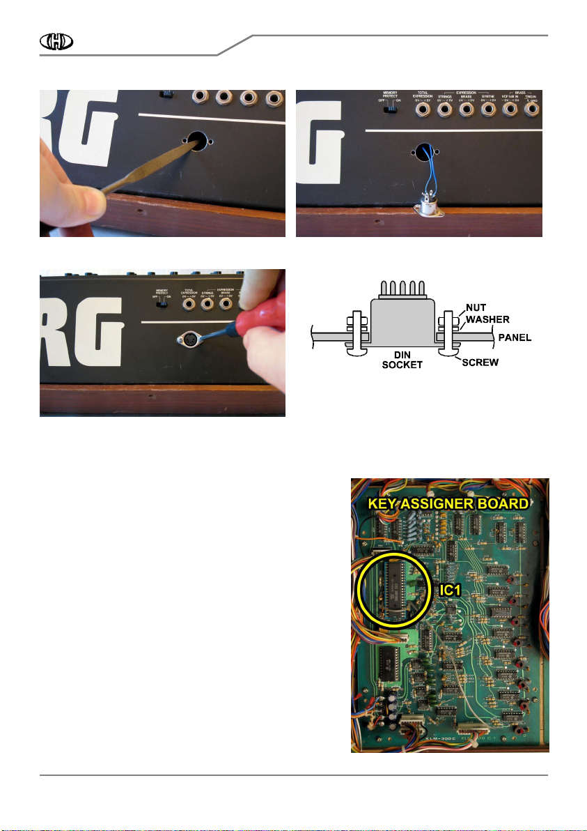
c) Clean the edge of the holes with small rasp (pic. 2.2-5). Also clean the holes from the inside after the
turning over the front cover.
d) Clean all iron sawdust and raspings from the inside of the instruments
Clean all iron sawdust and raspings from the inside of the instrumentsClean all iron sawdust and raspings from the inside of the instruments
Clean all iron sawdust and raspings from the inside of the instruments, they can cause short circuits or
serious electrical damage if left in the instrument. Please clean the instrument carefully!
e) Get flat connector of MIDI cable through the hole in rear panel into the instrument (pic. 2.2-6).
f) Insert the DIN connector into hole in rear panel (pic. 2.2-7) and fix the connector to the panel. Use two
screws, nuts and washers - parts of the kit (pic. 2.2-8). Hold the nuts with help of pliers for example during the
fixing.
TR2-KBD
MIDI Interface for Korg Trident Keyboard
Model 8-436 ver. 1.0
Copyright © 2018 CHD Elektroservis.
All rights reserved. No part of this publication may be reproduced in any form without the written permission of CHD Elektroservis.
6
Pic. 2.2
Pic. 2.2Pic. 2.2
Pic. 2.2-
--
-5
55
5
Pic. 2.2
Pic. 2.2Pic. 2.2
Pic. 2.2-
--
-6
66
6
Pic. 2.2
Pic. 2.2Pic. 2.2
Pic. 2.2-
--
-7
77
7
Pic. 2.2
Pic. 2.2Pic. 2.2
Pic. 2.2-
--
-8
88
8
g) You may also want to label the MIDI connector ("MIDI INPUT") using self-adhesive, for example.
Pic. 2.3
Pic. 2.3Pic. 2.3
Pic. 2.3-
--
-1
11
1
2.3
2.32.3
2.3
FLAT CABLE MONTAGE
FLAT CABLE MONTAGEFLAT CABLE MONTAGE
FLAT CABLE MONTAGE
Flat cable (part of delivery) has 14-pin connector on one end and
free wires on the other end. Partial wires are numbered
sequentially from 1 to 14, wire Nr. 1 has different color. It is
necessary to solder these wires to instrument’s “Key Assigner“
board – to leads of processor IC1 (pic. 2.3-1).
The wires can be soldered to leads of IC1 directly (from top side)
but it can evocate a problems – IC1 is placed in socket which can
be damaged during soldering. Beter method is to solder the wires
to pads on bottom side of”„Key Assigner“ board:
a) Unscrew eight screws from “Key Assigner“ board (pic. 2.3-2).
Do not lose them. They will be used again after the cable
montage.
b) Flip the board bottom side to top (pic. 2.3-3). Be careful that
original bunched cables connected to the board are not damaged
– disconnect their connectors from the board if necessary.

TR2-KBD
MIDI Interface for Korg Trident Keyboard
Model 8-436 ver. 1.0
Copyright © 2018 CHD Elektroservis.
All rights reserved. No part of this publication may be reproduced in any form without the written permission of CHD Elektroservis.
7
Pic. 2.3
Pic. 2.3Pic. 2.3
Pic. 2.3-
--
-2
22
2
Pic. 2.3
Pic. 2.3 Pic. 2.3
Pic. 2.3-
--
-3
33
3
c) Solder pads on bottom side of “Key Assigner“ board (KLM-300 / KLM-377) for partial wires of flat cable are
shown on pic. 2.3-4 and described in table below.
Pic. 2.3
Pic. 2.3Pic. 2.3
Pic. 2.3-
--
-4
44
4

TR2-KBD
MIDI Interface for Korg Trident Keyboard
Model 8-436 ver. 1.0
Copyright © 2018 CHD Elektroservis.
All rights reserved. No part of this publication may be reproduced in any form without the written permission of CHD Elektroservis.
8
Table
Table Table
Table –
––
– Solder pads on KLM
Solder pads on KLM Solder pads on KLM
Solder pads on KLM-
--
-300 / KLM
300 / KLM300 / KLM
300 / KLM-
--
-377 board
377 board377 board
377 board
Wire Nr. Signal Solder pad Pin of IC1 Nr. Remarks
1
11
1
2
22
2
+5V VCC 40
4040
40
both wires (1+2) are soldered to this pad, wire
Nr. 1 has different color
3
33
3
Address 0 P10 27
2727
27
4
44
4
Address 1 P11 28
2828
28
5
55
5
Address 2 P12 29
2929
29
6
66
6
Address 3 P13 30
3030
30
7
77
7
Data 5 P25 36
3636
36
8
88
8
Data 4 P24 35
3535
35
9
99
9
Data 3 P23 24
2424
24
10
1010
10
Data 2 P22 23
2323
23
11
1111
11
Data 1 P21 22
2222
22
12
1212
12
Data 0 P20 21
2121
21
13
1313
13
14
1414
14
GND VSS 20
2020
20
both wires (13+14) are soldered to this pad
Solder partial wires of flat cable to required pads on “Key Assigner“ board (pic. 2.3-5). Solder carefully so that
no short connection occurs between solder pads. This can disallow right function of the instrument. In extreme
case, some components on “Key Assigner“ board can be damaged!
Pic. 2.3
Pic. 2.3Pic. 2.3
Pic. 2.3-
--
-5
55
5
TR2-KBD
MIDI Interface for Korg Trident Keyboard
Model 8-436 ver. 1.0
Copyright © 2018 CHD Elektroservis.
All rights reserved. No part of this publication may be reproduced in any form without the written permission of CHD Elektroservis.
9
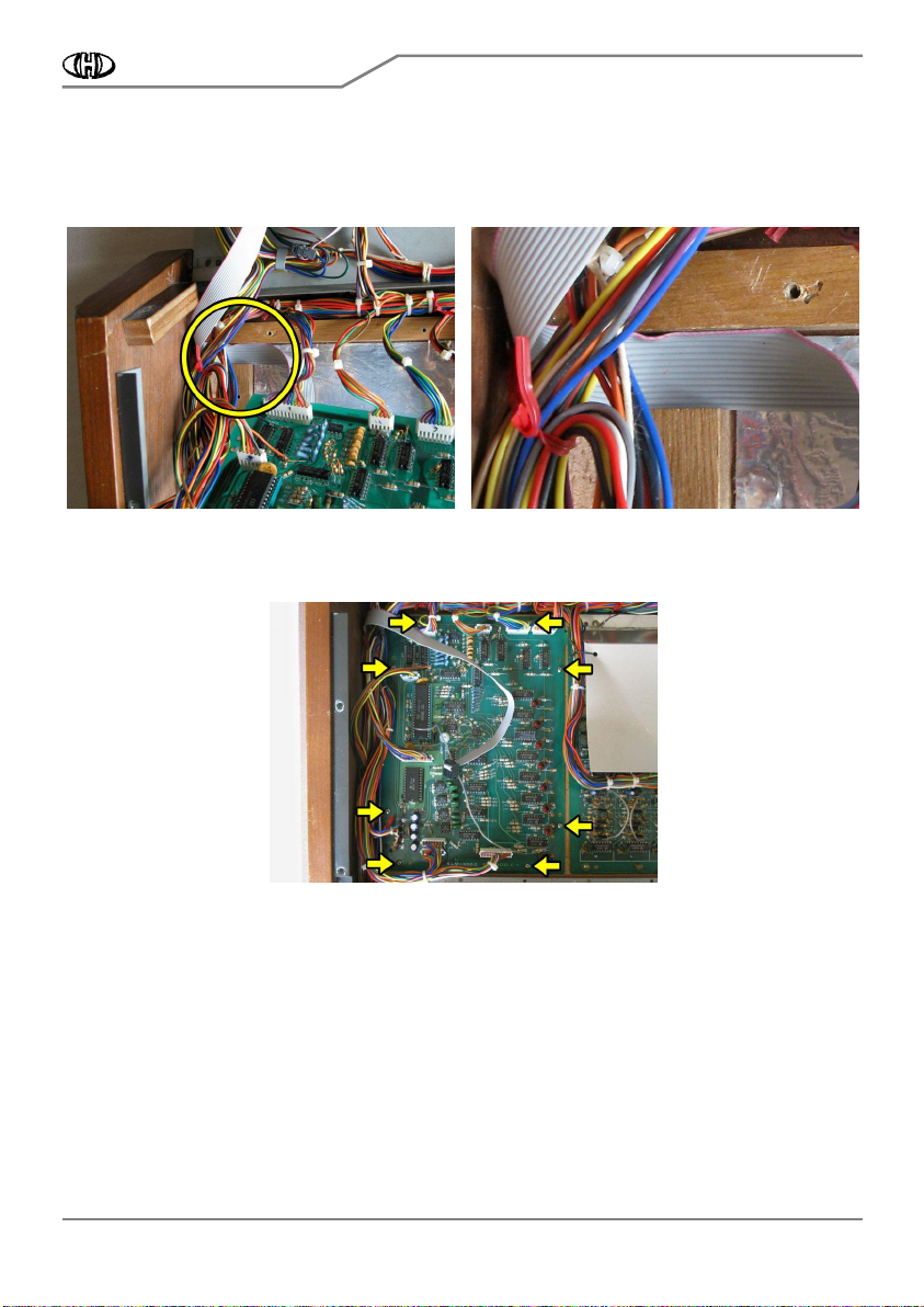
d) Flip “Key Assigner“ board back to its original position. Be sure that flat cable isn’t clawed by the board – the
cable must go via slot between wood supports in upper left corner of place for “Key Assigner“ board (pic. 2.3-6,
2.3-7).
Pic. 2.3
Pic. 2.3Pic. 2.3
Pic. 2.3-
--
-6
66
6
Pic. 2.3
Pic. 2.3 Pic. 2.3
Pic. 2.3-
--
-7
77
7
e) Fit “Key Assigner“ board back to bottom part of the instrument with previously removed screws (pic. 2.3-8).
Pic. 2.3
Pic. 2.3Pic. 2.3
Pic. 2.3-
--
-8
88
8
2.4
2.42.4
2.4
INTERFACE BOARD
INTERFACE BOARD INTERFACE BOARD
INTERFACE BOARD INSTAL
INSTALINSTAL
INSTALLATION
LATIONLATION
LATION
a) Cleanse (degrease) the part of rear panel inside of instrument to place there the interface board (pic. 2.4-1).
b) Remove the protective foil form the self-adhesive supports of the interface board (pic. 2.4-2).

TR2-KBD
MIDI Interface for Korg Trident Keyboard
Model 8-436 ver. 1.0
Copyright © 2018 CHD Elektroservis.
All rights reserved. No part of this publication may be reproduced in any form without the written permission of CHD Elektroservis.
10
Pic. 2.4
Pic. 2.4Pic. 2.4
Pic. 2.4-
--
-1
11
1
Pic. 2.4
Pic. 2.4 Pic. 2.4
Pic. 2.4-
--
-2
22
2
c) Apply the interface board to the part of the instrument’s panel so that connectors are on right side (pic. 2.4.-
3). Than fix the self-adhesive supports by pressing down.
d) Put two-pin connector of MIDI cable (X1 connector – see pic. 2) to plug on the interface’s board. Orientation
of the connector is unambiguously given by the connector locks (pic. 2.4-4).
Pic. 2.4
Pic. 2.4Pic. 2.4
Pic. 2.4-
--
-3
33
3
Pic. 2.4
Pic. 2.4 Pic. 2.4
Pic. 2.4-
--
-4
44
4
Pic.
Pic. Pic.
Pic. 2.4
2.42.4
2.4-
--
-5
55
5
e) Put the 14-pin connector of flat cable (X2 connector
– see pic. 2) to plug on the interface’s board.
Orientation of the connector is unambiguously given
by the connector lock (pic. 2.4-5).
TR2-KBD
MIDI Interface for Korg Trident Keyboard
Model 8-436 ver. 1.0
Copyright © 2018 CHD Elektroservis.
All rights reserved. No part of this publication may be reproduced in any form without the written permission of CHD Elektroservis.
11
2.5
2.52.5
2.5
INSTRUMENT ASSEMBLY
INSTRUMENT ASSEMBLYINSTRUMENT ASSEMBLY
INSTRUMENT ASSEMBLY
a) Turn over the front panel of the instrument.
b) Reattach the front panel to the sides of the instrument with six screws (pic. 2.5-1) and reattach six screws to
the rear side of the cover (pic. 2.5-2). This is the reverse procedure of that described in the chapter 2.1.
Pic.
Pic.Pic.
Pic. 2.5
2.5 2.5
2.5-
--
-1
11
1
Pic. 2.5
Pic. 2.5 Pic. 2.5
Pic. 2.5-
--
-2
22
2
The installation of the MIDI kit is now complete and the instrument is ready to communicate over the
MIDI. Please read carefully the user manual first.
Document :
8436_install_rev2
Manufacturer :
CHD Elektroservis
CHD ElektroservisCHD Elektroservis
CHD Elektroservis
Nad kundratkou 27, 19000 Praha 9, Czech Republic
info@chd-el.cz www.chd-el.cz
7
Table of contents
Other CHD Media Converter manuals


Popular Media Converter manuals by other brands


Cambridge Audio
Cambridge Audio DacMagic 200M manual

MEFE
MEFE CAT 200BC Operation manual

Moxa Technologies
Moxa Technologies VPort 461 Series Quick installation guide

Musical Fidelity
Musical Fidelity M1 DAC Instructions for use

DEWESOFT
DEWESOFT DS-IRIG-ACDC2 Technical reference manual

Fracarro
Fracarro SMART SWITCHLINE XS manual