Chemglass Life Sciences JACKETED FILTER User manual

www.cglifesciences.com technical-service@cglifesciences.com
3800 N. Mill Road
Vineland, NJ 08360
Phone: 800.843.1794
Fax: 800.922.4361
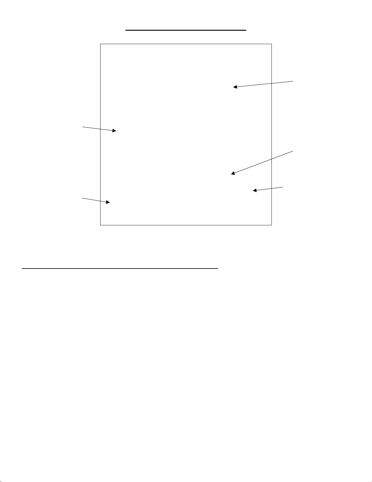
ASSEMBLY INSTRUCTIONS FOR
JACKETED FILTER
REACTOR SYSTEMS
Support Frame with
Oversized Rugged S.S.
Uprights and Heavy-
Duty PTFE Coated
Aluminum Fittings
Mechanical Seal
Stir Bearing
PTFE Filter Base
Open Frame
Design for
Excellent
Accessibility
Heavy Duty
Lockable Castors
Detachable Drain
Valve
20L Vessel Body
S.S. Inlet/Outlet
Adapters Available
in M16 x 1 and M30

www.cglifesciences.com technical-service@cglifesciences.com
PLEASE NOTE: FILTER REACTORS ARE FOR VACUUM/GRAVITY FILTRATION USE ONLY.
Read Entire Assembly Instructions Before You Begin. Familiarize Yourself with All of the Parts,
and Pay Close Attention to All Notes and Highlights.
Support frames are shipped via common carrier and require loading dock access with a fork lift or
jack. If you do not have a loading dock, then a lift gate-equipped truck must be requested at the
time of order.
For your convenience, the jacketed process filter reactor, the fully assembled reactor head, stirrer shaft
& agitators, Tru-Stir™ stirrer shaft coupling, PTFE stirrer bearing, temperature probe & adapter, S.S.
inlet/outlet adapters, and motor are shipped assembled on the support frame. PTFE sleeves and keck
clips are available separately.
Unpack all of the parts and check against the packing slip to make sure you have received all
necessary components. If possible, keep some of the packaging materials from the wood crates in
case you need to return items for repair or replacement.
Crate # 1:
•Unpack the support frame with reactor and components by removing the plastic electrical
ties that hold the reactor in place and remove the cardboard/foam packing from around the
reactor. Re-tighten all of the Allen screws with the supplied wrenches, adjust all black knobs
and tighten torque knobs. The red silicone pad should be touching the straight section of the
glass below the reactor flange. CHECK ALL ALLEN SCREWS BEFORE PROCEEDING; SCREWS CAN
LOOSEN DURING SHIPMENT.
•Attach the Tru-Stir™ stirrer shaft coupling to the 1/4 HP electric stirrer motor.
Crate # 2:
•Contains the 0-14mm drain valve, motor controller/temperature monitor and other
miscellaneous parts.
Move the reactor assembly and parts near the hood or area where the reactor will be used, but
allow enough space to move freely around the support frame. During setup, preparation, and
process, it is best to keep the wheels in their locked position by stepping down on the tab.
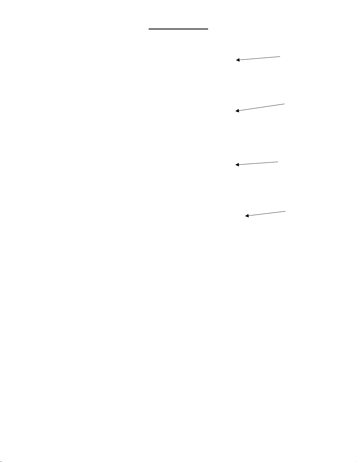
Black Knobs
for Vertical
Height
Adjustment
Torque
Knobs
*PLEASE NOTE:
Torque knobs should be
checked periodically to
ensure the torque function
has not been adversely
affected by corrosion.

www.cglifesciences.com technical-service@cglifesciences.com
Overhead Stirrer Motor
Air Motor 1/4 HP Vertical Motor
1/4 HP Horizontal Motor Explosion Proof (XP) Motor
The motor is installed on the support frame when shipped. Use the following instructions should you
need to remove or adjust these components.
Components Needed for Overhead Stirrer Motor:
1ea CG-2033-B-25 1/4 HP Vertical Electric Stirrer Motor
1ea CG-2025-20 Air Motor* (Optional)
1ea CG-2033-V-75 Motor Controller/Temperature Monitor (Only Supplied with 1/4 HP Electric
Stirrer Motor)
1ea CG-2044 Tru-Stir™ Stirrer Shaft Coupling
1ea CG-9253-10 Small Kwik Klamp II
1ea CG-3498-03 90° Support Rod
1. The support frame has a universal motor mount. It can be used with an (vertical or horizontal)
electric, air, or optional explosion proof (XP) motor. The mount automatically centers the motor
directly above the reactor.
2. The 1/4 HP electric motor is shipped attached to the support frame via four socket head cap
screws.
3. When using the 1/4 HP electric motor, the motor controller/temperature monitor, with
mounting bracket on side panel, needs to be mounted on the S.S. upright. Use the small Kwik
Klamp II and the 90°S.S. support rod to mount the controller to the support frame. Tighten all
knobs securely.
*The Air Motor requires the air supply be filtered and a lubricator be installed between the air source
and motor. Filter-Regulator-Lubricator (CG-2025-10) is available separately.
www.cglifesciences.com technical-service@cglifesciences.com
Stirrer Shaft and Agitator Assembly
The stirrer shaft and agitators are assembled and installed when shipped. Use the following
instructions should you need to remove or adjust these components.
Components Needed for Stirrer Shaft and Agitator Assembly:
1ea CG-2097 Stirrer Shaft
1ea CG-2093 Flake Retaining Cup
1ea CG-2095 Upper PTFE Agitator
1ea CG-2096 Lower High Viscosity PTFE Agitator
1. The lower agitator assembly (CG-2096) is placed on the end of the stirrer shaft aligning the
hole on the stirrer shaft with the holes in the PTFE hub. The sand blasted portion is the lower end
of the stirrer shaft. Insert the glass filled PTFE pin. The pin must be cut to 24mm long before
installing. Tighten the compression fitting. PLEASE NOTE: THE PTFE PIN MUST BE INSTALLED BEFORE
USING.
2. The upper agitator assembly (CG-2095) slides over the end of the shaft. The height from the
bottom will depend on the total volume you intend to run in the reactor.
3. Once you have the upper agitator in place, tighten the compression fitting as tight as possible
(by hand). For use at higher temperatures, Chemglass recommends heating the upper
agitator hub with a heat gun and then retightening. Then tighten the set screw on the flat of
the stirrer shaft using a screwdriver. This will minimize the possibility of the agitator falling or
slipping at higher temperatures.
4. The PTFE flake retaining cup (CG-2093) slides over the top of the stirrer shaft and is positioned
approximately 18 inches from the bottom of the lower agitator assembly (CG-2096). For the
cup to work effectively, the final position will have to be adjusted so that it is not less than 1
inch away from the bottom of the PTFE stirrer bearing.
CG-2095
Upper Agitator
CG-2096
Lower Agitator
CG-2097
Stirrer Shaft
Hole through the
Lower Portion of the
Stirrer Shaft
Glass Filled PTFE Pin
(MUST BE CUT TO
LENGTH BEFORE
INSTALLING)
www.cglifesciences.com technical-service@cglifesciences.com
Filter Base System
1. Place the o-ring in the beveled edge of the filter base.
2. Place the perforated plate in the filter base, beveled edge facing up.
3. Place the frit (filter) on top of the perforated plate.
4. Fix the centering ring on top of the frit and make sure it is pushed down on all edges
evenly.
5. Wrap the lower outlet adapters with NPT end with PTFE tape. Thread the adapter into the
filter base until it becomes snug. DO NOT OVER TIGHTEN.
6. Attach the beaded pipe coupling to the lower outlet drain and the CG-1959-A-01 0-
14mm drain valve. Torque the beaded pipe coupling to 35in-lbs using a torque wrench.
PLEASE NOTE: MAXIMUM TEMPERATURE LIMIT FOR FILTER BASE IS 150°C
Centering Ring
Frit (Filter)
*Note: The Bottom
Impeller Should NOT
Rub on the Filter
Perforated Plate
Filter Base
Table of contents
Other Chemglass Life Sciences Laboratory Equipment manuals


Popular Laboratory Equipment manuals by other brands


Belden
Belden HIRSCHMANN RPI-P1-4PoE installation manual

Koehler
Koehler K1223 Series Operation and instruction manual

Globe Scientific
Globe Scientific GCM-12 quick start guide

Getinge
Getinge 86 SERIES Technical manual

CORNING
CORNING Everon 6000 user manual

Biocomp
Biocomp GRADIENT MASTER 108 operating manual


