Chemyx FUSION X Series User manual

FUSION X SERIES
USER MANUAL FOR NEW FUSION 100-X & 200-X
INTELLECTUAL PROPERTY
All Intellectual Properties, as dened below, owned by or which is otherwise the property of Chemyx Inc. or its suppliers relating to the Chemyx syringe pumps, including but not limited to, accessories,
parts or software relating thereto (Chemyx Syringe Pumps), are proprietary to federal and state laws, and international treaty provisions. Intellectual Property includes but is not limited to, inventions
(patentable or unpatentable), patents, trade secrets, copyrights, software, rmware, computer programs, and related documentation and other works of authorship. Moreover, you agree that you will
not, and will not attempt to, modify, prepare derivative works of, reverse engineer, disassemble the Chemyx syringe pumps, decompile or otherwise attempt to create source code from the related
software/rmware. No title to or ownership in Intellectual Property is transferred to you. All applicable rights of the Intellectual Property shall remain with Chemyx and its suppliers.

2
Geberal Description 4
Safety Information 4
Warranty and Repair Information 5
Product Overview 6
Principle of Operation 6
Controlled Elements 7
Controls 8
Fusion 200-X Specic Componets 8
Specications 9
Pump Setup 11
Loading a Syringe 11
Adjusting the Safety Nut 11
Pump Operation 13
Navigating Between Screens 13
Mode Selection Screen 14
Syringe Selection 15
Volume 16
Infusion/Withdrawal (Fusion 200-X only) 17
Flow Rate 17
Options 18
Saving Run Parameters 18
Priming/Bolus Rate 18
Multi-Step Mode 20
Setup 20
Syringe Selection 20
Total Steps 21
Loop All 21
Sub-Loops 21
Step Parameters 22
Flowrate 22
Table Of Contents

3
Start Time Delay 22
Step Loop 22
Pump Control 24
Run Status 25
Load Run 26
System Settings 26
Touchscreen Toggle 26
Baud Rate 26
Motor Power` 27
LCD Power-O Time 27
Pump Control by Computer 28
Cable Requirements and connecting 28
COM Port Settings 29
Pump Commands 30
Chemyx Pump Controller Programs 35
Pump Maintenance 36
Lubricating the Pump 36
Calibrations 36
Pump Accessories 37
Footswitch 37
Connecting the Footswitch 37
Using the Footswitch 37
11 Channel Syringe Rack 37
Attaching the Rack 38
Appendices 40
Contact Information 43

4
General Description
Please read the following safety precautions to ensure personal safety and operational longevity of the Chemyx syringe pump.
Chemyx is not responsible for the equipment if used in a manner not specied by the manufacturer; warranty coverage
provided by the equipment may be dropped as a result.
CHEMYX PRODUCTS ARE NOT APPROVED FOR CLINICAL USE ON HUMANS.
Safety Information
Warranty coverage will be lost if the pump is opened without authorization from Chemyx. Do
not touch any electrical connectors on or in the product.
Even though the pump can operate at extremely fast speeds, the user must determine the
proper ow rate for any given application. For instances, pumping at 90 mL/min using a
20-gauge needle will cause stalls and/or potential bursting of the syringe. Chemyx is not
responsible for any damage that might result from situations similar to the example above.
Do Not Open The Pump
Do Not Operate With Suspected Failures
Do not place ngers between the pusher block and the end block while the pump is running.
Read all labels on the product to ensure proper usage.
The user is responsible for wetting ground glass syringes and setting and tightening the safety
collar/bar appropriately.
Pinch Hazard
Observe all Warning labels on Product
Chemyx is not Responsible for Syringe Damage

5
Warranty & Repair Information
Chemyx provides a two-year limited warranty from the shipment date for its pumps against defects in materials
and workmanship. Chemyx will repair any product that proves defective during its stated warranty period.
The foregoing warranty will not apply to damage resulting from:
You must contact Chemyx (call +1 281-277-5499 or visit www.chemyx.com/contact-us) before returning a product.
Chemyx will issue a Return Authorization (RA) number to you.
Return products to: Chemyx Inc. 10905 Cash Road | Staord, TX 77477 USA.
Warranty Information
Improper or inadequate maintenance or operation.
Unauthorized modication or misuse of the product.
Operation outside the electrical specications for the product.
Operation outside the temperature specications for the product.
User-induced internal and external contaminations of the instrument.
Failure to use proper surge protection.
Improper product return, packaging, and shipping
During the LCD Monitor manufacturing process, it is not uncommon for one or more pixels to become xed in an unchanging
state. The visible result is a xed pixel that appears as an extremely tiny, dark or bright dot. In almost every case, these xed
pixels are hard to see and do not detract from display quality or usability. A display with three to seven bright or dark dots is
considered normal and within industry standards. If your screen displays more than seven dead pixels during the warranty
period, your system will qualify for warranty replacement. Please see the Limited Warranty section for details on how to activate
a warranty claim.
The serial number is located on the back, top left corner or center of the pump under a small barcode. Removal of the serial
number label will void the warranty.
Dead Pixel Policy
Serial Numbers
Return Address
6
Product Overview
Chemyx Fusion Series syringe pumps are designed to handle every type of high-precision dosing application. The units’ exibility
with syringe types and sizes and an advanced software interface make this line of high-precision syringe pumps integrable
into any operation or laboratory work ow. Thoroughly durable both inside and out, the Chemyx Fusion syringe pumps are
designed to provide years of constant and reliable service.
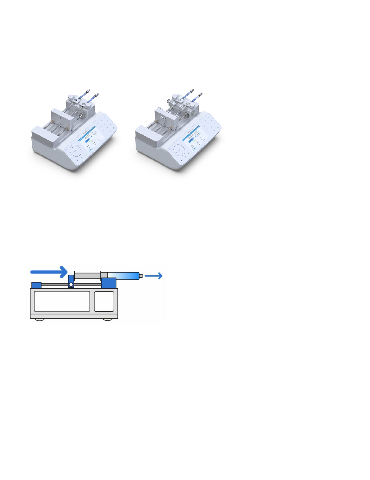
A syringe pump is a small, positive-displacement pump used to gradually transfer precise volumes of uid. All Chemyx Fusion-
series syringe pumps are driven via a stepper motor. This stepper motor precisely turns a lead screw that is threaded through
a pusher block, which causes the pusher block to move. When the pump is in infusion mode, the pusher block pushes against
the plunger of a secured syringe, causing the uid to be ejected at an accurate and precise rate.
If the pump is capable of withdrawal, the plunger of the syringe is held by brackets on the pusher block. When the stepper
motor turns in the opposite direction, the pusher block moves such that the syringe plunger is pulled, thus drawing uid into
the syringe.
For the Fusion Series syringe pumps, the pusher block moves to the right for infusion and to the left for withdrawal.
Principle of Operation
Fusion 100-X Fusion 200-X

7
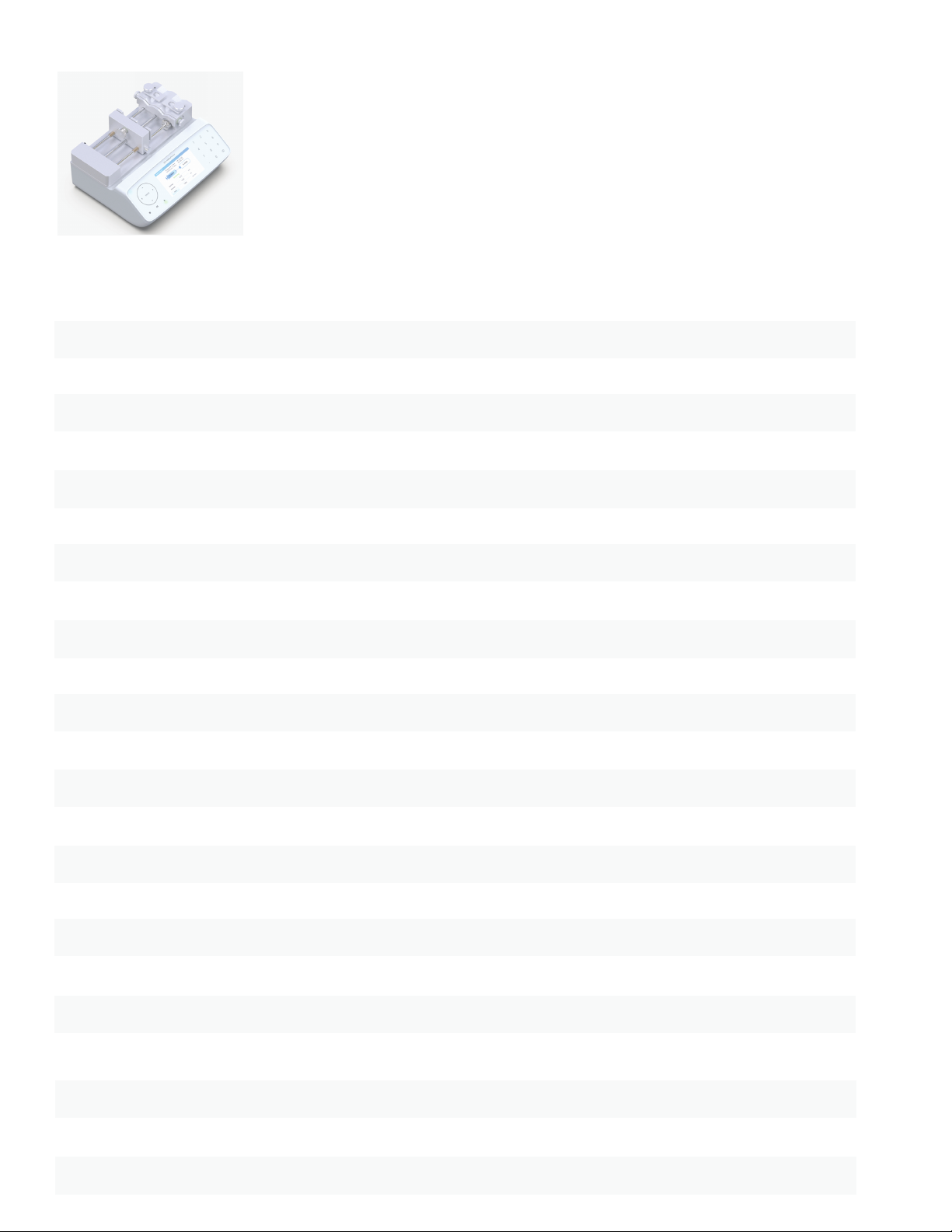
All Fusion Series pumps have a single lead screw through which the pusher block is threaded. The pusher block moves when
the lead screw turns. The two guide rods keep the pusher block horizontal and perfectly perpendicular to the lead screw. The
block-release button disengages the pusher block from the lead screw, which allows the pusher block to be easily moved to a
new position as long as the button is held. Releasing the button will lock the pusher block back in place.
Syringes are placed on the syringe-holder block in the v-shaped grooves, or channels, and held securely using syringe clamps.
The Fusion 100-X and 200 both have two syringe channels, while the Fusion 400 has four smaller syringe channels.
The safety collar of the Fusion 100-X and 200-X helps protect the integrity of syringes by keeping the pusher block from pushing
on a completely depressed syringe.
Controlled Elements
Block Release Button Syringe Holder Block
Safety Collar
Lead Screw Guide Rods
Pusher Block Syringe Clamp
Syringe Channels
Fusion 100-X pump components
8
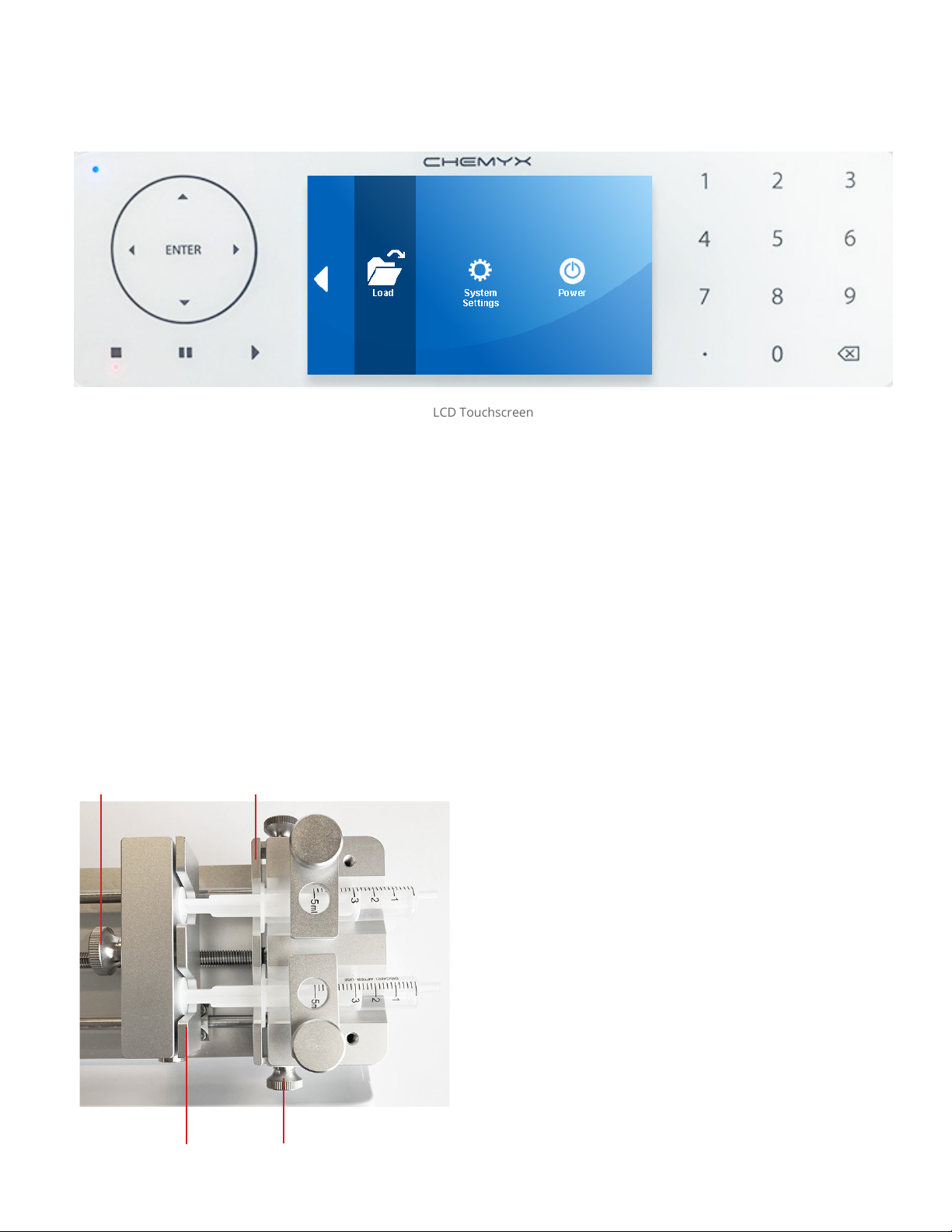
The Fusion Series uses a full glas LCD touchscreen with an intuitive graphical user interface (GUI) for setting up detailed pump
run methods. Buttons and entry elds within the GUI are all selectable using the touchscreen. As a resistive, LCD touchscreen,
the interface can be operated with any object, not just the touch of a ngertip. Selecting elements by touch only requires a small
amount of pressure; however, please do not use sharp objects as they may damage the screen.
The Fusion series also includes physical navigation controls, allowing users to manually maneuver between selectable GUI
elements without touching the screen. Inputting numbers and letters within the GUI is done using the physical numeric keypad.
The physical pump control keys are used to start, pause, and stop pump activity.
Navigation Keypad Front Panel of Pump
Controls
Pump Controls LCD Touchscreen Numeric Keypad
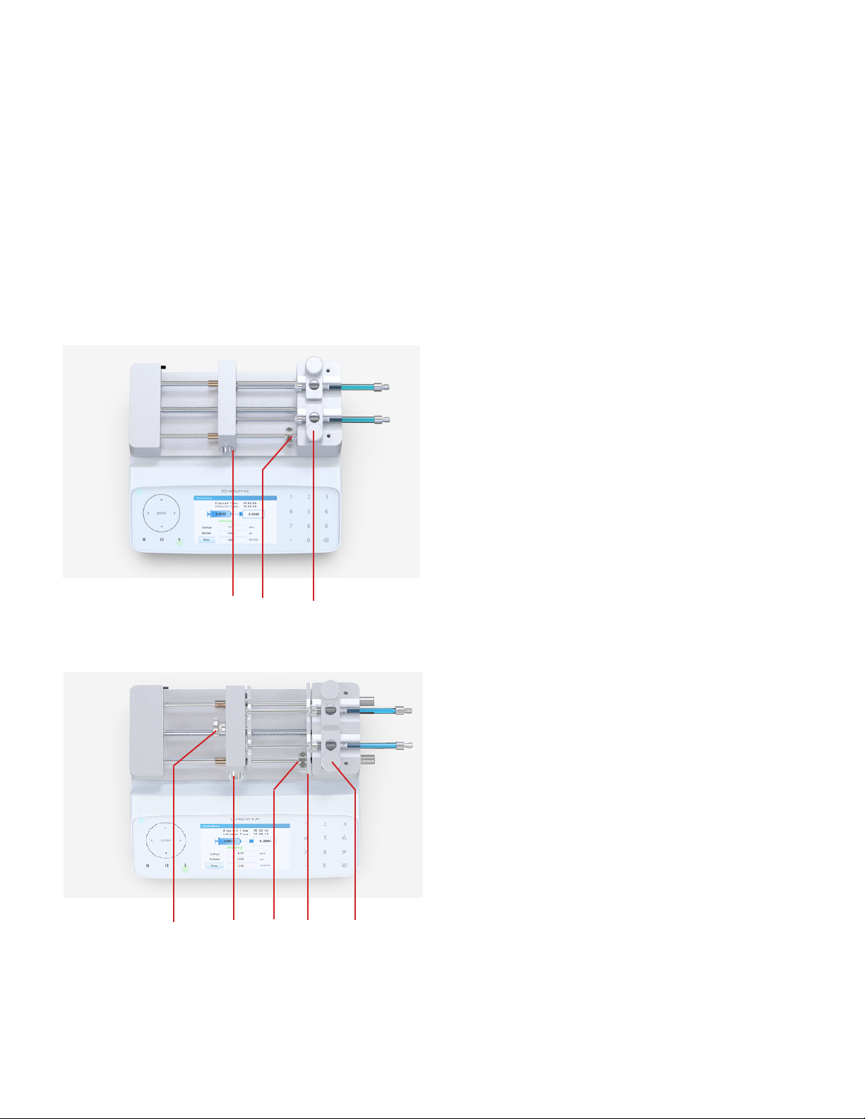
In addition to having all of the same features and
components of the Fusion 100-X, the Fusion 200-X is capable
of both infusion and withdrawal. Because of this dierence,
the Fusion 200-X uses adjustable retaining brackets on the
pusher block and the syringe-holder block that keep the
syringe in place during both infusion and withdrawal.
Bracket Release Knob Flange Retaining Bracket
Plunger Retaining Bracket Bracket Release Knob
Fusion 200-X Specic Components
9
65lb (29.4kg)
TECHNICAL SPECIFICATIONS
Infuse/Withdraw
± < 0.35%
± < 0.05%
0.5µL to 60mL
Plasc, Glass and Stainless Steel
See Syringe Library for Min & Max Flow Rates on Website
0.0001 µL/min (with 0.5µL syringe)
85 mL/min(with 50mL syringe)
4.3 inch LCD Touch Screen
USB-B, RS232 and TTL Ports
Mode
Accuracy
Reproducibility
Syringe Size (Min/Max)
Syringe Type
Syringe Flow Rates
Minimum Flow Rate
Maximum Flow Rate
Linear Force
Display
Connecvity
Weight
Motor Drive
Step Resoluon
7lbs (3.1kg)
.
0.0528 µm/step
Fusion 200-X Data Sheet
System Dimensions 9.5 x 8.2 x 4.9 inches (24 x 20.8 x 12.4 cm)
1.8˚ Stepper Motor with Micro-stepping
Power
For More Informaon visit chemyx.com Chemyx Syringe Pumps are not for human use
Storage Temperature -10°C to 70°C (14°F to 158°F)
Humidity 20% to 80% RH, non-condensing
Installaon Category II
Regulatory Compliance CE, RoHS, REACH, ETL
Operang Temperature 4°C to 40°C (40°F to 104°F)
The Fusion 200-X is a modular pump with a full glass touch
color screen, a strong pushing force and automacally
switches between 110V to 220V. A new accessory of
11-syringe rack can be added on to the pump.
Program steps up to 99 step / loop steps up to 99 loop
Mul Steps
Parameter Seng Opon to choose me or rate
Modular Capability Opon to add a 11 syringe rack
110/220 VAC automacally switches between 110V to 220V 30 Was

10
55lb (25kg)
TECHNICAL SPECIFICATIONS
Infuse Only
± < 0.35%
± < 0.05%
0.5µL to 60mL
Plasc, Glass and Stainless Steel
See Syringe Library for Min & Max Flow Rates on Website
0.0001 µL/min (with 0.5µL syringe)
157 mL/min (with 60mL syringe)
4.3 inch LCD Glass Touch Screen
USB-B, RS232 and TTL Ports
Mode
Accuracy
Reproducibility
Syringe Size (Min/Max)
Syringe Type
Syringe Flow Rates
Minimum Flow Rate
Maximum Flow Rate
Linear Force
Display
Connecvity
Weight
Motor Drive
Step Resoluon
7lbs (3.1kg)
.
0.098 µm/step
Fusion 100-X Data Sheet
System Dimensions 9.5 x 8.0 x 4.9 inches (24 x 20 x 12 cm)
1.8˚ Stepper Motor with Micro-stepping
Power
For More Informaon visit chemyx.com Chemyx Syringe Pumps are not for human use
Storage Temperature -10°C to 70°C (14°F to 158°F)
Humidity 20% to 80% RH, non-condensing
Installaon Category II
Regulatory Compliance CE, RoHS, REACH, ETL
Operang Temperature 4°C to 40°C (40°F to 104°F)
The Fusion 100 X is a modular pump with a full glass touch
color screen, a strong pushing force and automacally switches
between 110V to 220V. A new accessory of 11-syringe rack can
be added on to the pump.
Program steps up to 99 step / loop steps up to 99 loop
Mul Steps
Parameter Seng Opon to choose me or rate
Modular Capability Opon to add a 11 syringe rack
110/220 VAC automacally switches between 110V to 220V 30 Was
11
The Fusion series can accommodate up to two syringes in the Fusion 100-X and 200 X models, while the Fusion 400 can house
up to four syringes. The Fusion 200-X can be expanded to 10 channels using the Chemyx 10-Channel Syringe Rack accessory.
The volume of the syringes can vary from a minimum of 0.5 μL up to a maximum of 60 mL (10 mL maximum for the Fusion 400).
Syringes of any material (e.g., glass, plastic, stainless steel, etc.) can be used; however, some use cases may require syringes
that are more accurate and durable.
1. If necessary, move and tighten the infusion safety collar
(see Adjusting the Safety Collar).
2. While pressing in the lock-release button, slide the pusher
block all the way to the left.
3. Pull up on the spring-loaded syringe clamp and place
the syringe in one of the channels of the syringe-holder
block. Ensure that the ange of the syringe barrel is ush
against the edge of the syringe-holder block. Slowly lower
the syringe clamp to secure the syringe in place.
Loading a Syringe
Fusion 100-X
21 3
Pump Setup
1. If necessary, move and tighten the infusion safety collar
(see Adjusting the Safety Collar).
2. While pressing in the block release button, slide the
pusher block all the way to the left.
3. Loosen the screw knobs for the ange retaining bracket
and adjust the bracket such that the ange of the syringe
barrel will t in between. Do not tighten the bracket, yet.
4. Pull up on the spring-loaded syringe clamp and place the
syringe in one of the channels of the holder block. Ensure
that the ange of the syringe barrel is ush against the
edge of the holder block. Slowly lower the syringe clamp
to secure the syringe in place.
Fusion 200-X
231
5. Loosen the bracket clamp knob for the plunger retaining
bracket and adjust the gap such that the plunger cap of
the syringe may t.
4
5
12
The Fusion series of pumps can generate a signicant amount of linear force. While this is extremely useful for dispensing
viscous uids at higher ow rates, the higher linear force of the Fusion series can also potentially damage the syringes in
use. One source of potential damage of a syringe may occur when the plunger of the syringe is complete depressed, and
the pusher block is still pushing against the syringe. Depending on the material of the syringe (i.e., glass or plastic) and the
thickness of the plunger, the pressure from the pusher block could bend, distort, or just break the syringe.
To protect against this potential problem, Fusion syringe pumps use safety collars (Fusion 100-X and 200) and safety bars
(Fusion 400) to physically stop the pusher block before it can completely depress the syringe plunger. When a pusher block
hits the safety mechanism and can no longer move forward, the pump will stop running, emit a long beep, and enter pump-
stalled mode.
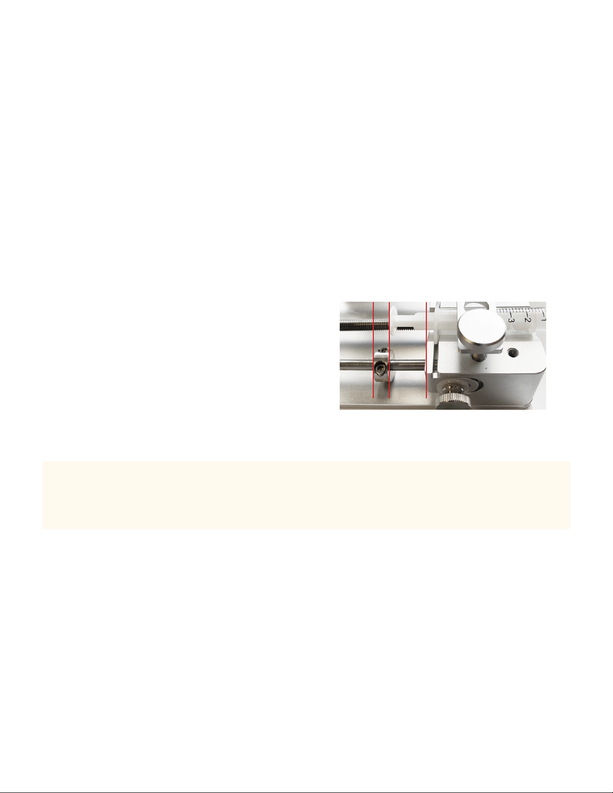
Adjusting the Safety Nut
Adjusting the safety collar requires the use of the hex key,
conveniently stored on the back left of the pump, right above the
power switch. Loosening the hex screw on the safety collar allows
for the collar to be slid freely along the guide rod and then securely
tightened to set the position of the safety collar. The position of the
safety collar should be set slightly further from the syringe-block
holder than the top of syringe plunger when fully depressed.
Fusion 100-X and 200-X
Caution:
On the Fusion 200-X, during withdrawal, a syringe plunger can potentially be pulled out from the syringe, which could cause the
contents of the syringe to leak out. Users should be especially aware of the length of the plunger and the point where the withdrawing
pusher block will exceed that length. There are no safety collars on the Fusion 200-X to prevent too much withdrawal.
Safety collar adjustment
13
The LCD screen displays a graphical user interface (GUI) from which all the pump settings and run parameters are entered.
Whenever an item is currently selected, the color scheme of the element typically turns to a darker shade of the color. For
example, the light blue buttons turn dark blue when selected, and the white background surrounding an unselected editable
text eld turns blue when the eld is selected and available for editing. Also, when a GUI element is selected, the top blue
bar will show the activity performed (buttons only) or show the limits to the values that may be entered for the selected eld
(editable elds only).
Selecting the items that will be modied can be done two ways: (1) using the LCD touch screen or (2) using the navigation
keypad.
All of the elements of the GUI can be interacted with by touch. Typical touch interactions are tapping a nger on a button or
text eld or sliding a nger to scroll. As a resistive touch screen, these interactions are not restricted to only ungloved ngertips.
Many types of objects can be used to select items on the screen with only very slight pressure, but avoid using sharp objects, as
they may permanently damage the screen.
Elements of the GUI may also be selected using the navigation keypad on the front of the instrument to move between the
elements.
To activate (or “press”) a button using the navigation keypad, select the button element such that it is highlighted and then press
the ENTER key at the center of navigation keypad. Editable elds can immediately be edited upon selection without the need
to press the ENTER key.
Pump Operation
Operating Interface
Limits for selected elds
Selected Fields
Unselected Field
Tip:
Users may nd the navigation keypad easier to use for scrolling through items in a scrollable list, such as the list of syringes in the
syringe library.
All of the screens in the Fusion Series GUI exist in a hierarchy, with the Mode Selection screen at the top. Entering a new screen
is performed simply by activating, or tapping, a button or icon that opens the new screen.
To return to the previous screen, tap or activate the red “X” button in the top right of the screen. This will
“close” the current screen, and return to the screen that was used to enter the closed screen. This can also be
accomplished by pressing the Stop key on the front of the instrument when the pump is not running.
Navigating Between Screens

14
Mode Selection Screen
The Mode Selection screen is the top level
menu for the Fusion series pumps. This screen
allows users to select the Basic or Multi-Step
modes, load a previously saved method, and
adjust system settings or power settings.
The Mode Selection screen consists of two
screens. Items on each screen can be tapped by
touch to enter the selected option. To maneuver
between the screens, the white triangular arrow
on the edge of the screen can be tapped to go
between the two screens. Users can also swipe a
nger on the screen to switch between screens.
Additionally, the navigation keypad can also be
used to select an item, and the ENTER key is
used to access the selected option.
For a description of the items listed in the Mode
Selection screen, please refer to the associated
section in this manual.
Mode Selection Screen 1
Mode Selection Screen 2

15
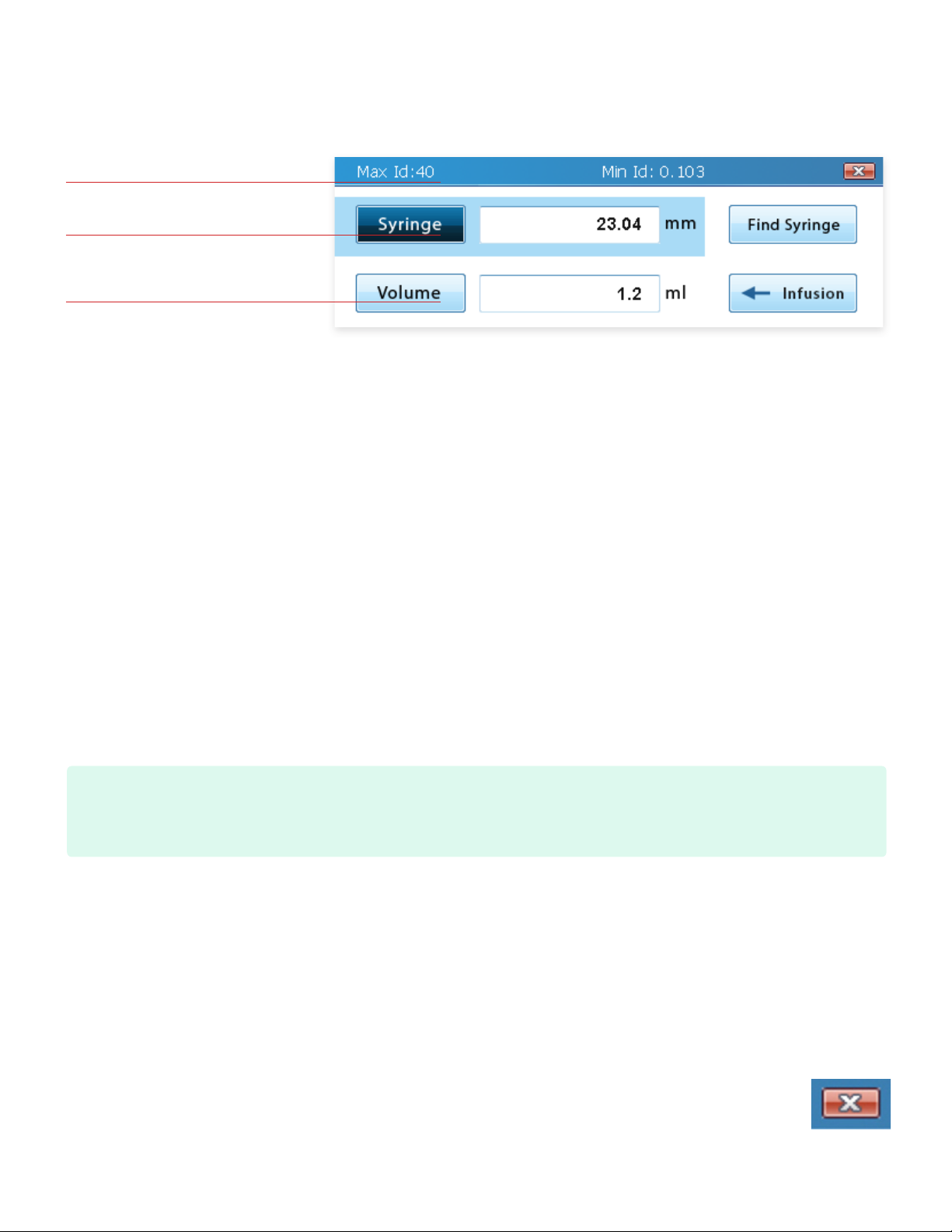
Syringe Selection
For every application, the rst required step for setup is to select the inner diameter (ID) of the syringe(s) being used. This value
is important for the syringe pump to accurately calculate the transfer rate and the total transferred volume for the liquid in the
syringe. There are two approaches to entering this value: (1) enter a custom inner diameter or (2) use the built-in syringe library
to import an inner diameter.
Entering a custom inner diameter (ID) is as simple as typing in the ID in millimeters in the Syringe editable eld. The maximum
and minimum values for the ID are displayed in the blue bar at the top of the screen while the Syringe editable eld is selected.
This value is also limited to only three decimal places, where any additional decimals or trailing zeroes are dropped. If the value
of the Volume eld is smaller/larger than the min/max volume allowed for the input inner diameter, the value in the Volume
eld will be adjusted to be within range. Otherwise, no changes to the volume will occur.
Tapping the Find Syringe button to the right of the Syringe
editable eld will open a new Syringe Library screen. Syringe
manufacturers are found in the list on the left. Selecting a
manufacturer will display all of the syringes available from
that manufacturer in the list on the right. The list of syringes
typically indicates the volume of the syringe rst, followed by
the inner diameter of the syringe. Both lists can be scrolled
through by dragging a nger on the scroll bar; however, the
easiest approach in this screen may be to use the navigation
keypad to scroll through the lists. A list of the syringes in the
library can be found in Appendix A.
Syringe Library Screen
When a particular syringe is selected from the list on the right, an Accept/Enter button will appear next to the selected item.
Tapping the Accept/Enter button (or pressing the Enter key on the navigation keypad) will import the inner diameter associated
with the selected syringe and exit the Syringe Library screen.
Upon import of a syringe from the syringe library, the Syringe editable eld will be updated to the new inner diameter, and the
Volume editable eld will be updated to the volume of the imported syringe. Please note that the volume units and values for
the Volume and Rate elds may change to match the units of volume displayed for the syringe in the Syringe Library.
Tip:
Because changing the values of the syringe ID may possibly change the values and units for volume and rate, selecting a syringe or
entering the syringe ID should always be the rst step when setting up a run.
Important Note:
If more than one syringe will be used at the same time, it is recommended that the all of the syringes be of the same inner diameter.
Because Fusion pumps calculate the rate that the pushing block moves based on the input syringe inner diameter and ow rate,
syringes with larger or smaller inner diameters will transfer more/less volume than indicated by the GUI.

16
Volume
The Volume eld represents the total volume of liquid that the pump will transfer (infusion or withdrawal) before stopping. The
amount of time that the pump will run with the set target volume can be determined by dividing the volume by the ow rate.
The value entered can be any integer or decimal within the limits for the syringe. The min/max volume limits can be found in the
blue bar at the top of the screen when the Volume eld is selected. Any entered value beyond these limits will be automatically
adjusted to the minimum or maximum limit, whichever is closer. The total number of decimal places is limited to ve.
The volume can be stated in units of mL or μL. The units used for the volume are dependent upon the set units of volume for
the ow rate in the Options screen.
To continuously run the pump and use the entire volume of the syringe, users can set the volume to the total volume of the
syringe or to the maximum limit. However, users are strongly encouraged to set the safety collar/bar (see Adjusting the Safety
Collar) so that the pump does not potentially ruin the syringe.
Important Note:
The maximum volume limit for a syringe assumes that the length of the syringe is the length of the pump. Therefore, this maximum
volume limit is almost always larger than the actual volume the syringe can hold.
Infusion/Withdrawal (Fusion 200-X only)
The Fusion 200-X is capable of both infusion and withdrawal. On Fusion 200-X systems, an Infusion/Withdrawal toggle button
should appear to the right of the Volume eld. The text and arrow direction on the button indicates the mode that is currently
set and direction that the pusher block will move upon starting the run. Tapping the button will switch between the two modes.
17
Flow Rate
The Flow Rate eld indicates how fast the pusher block will move. The amount of time that the pump will try to run can be
determined by dividing the set volume by the ow rate.
The value entered can be any integer or decimal within the limits for the syringe. The min/max ow rate limits can be found in
the blue bar at the top of the screen when the Rate eld is selected. Any entered value beyond these limits will be automatically
adjusted to the minimum or maximum limit, whichever is closer. The total number of decimal places is limited to ve.
The rate can be stated with four dierent units: mL/min, mL/hr, μL/min, and μL/hr. Adjusting the units will aect the min/max
limits for the Rate eld. The units for rate can be set in Options.
Caution:
Flow rate is often set for the needs of the experiment; however, users should be aware that setting high ow rates, especially for
viscous uids, may require high linear force beyond the limits of the pump which may cause the pump to stall out. Additionally, high
ow rates can exert tremendous pressure within a syringe that may cause glass or plastic syringes to burst. In the case of
high-pressure experiments, users should consider using Chemyx Stainless-Steel Syringes and the high-pressure Chemyx
Nexus 6000 pump.
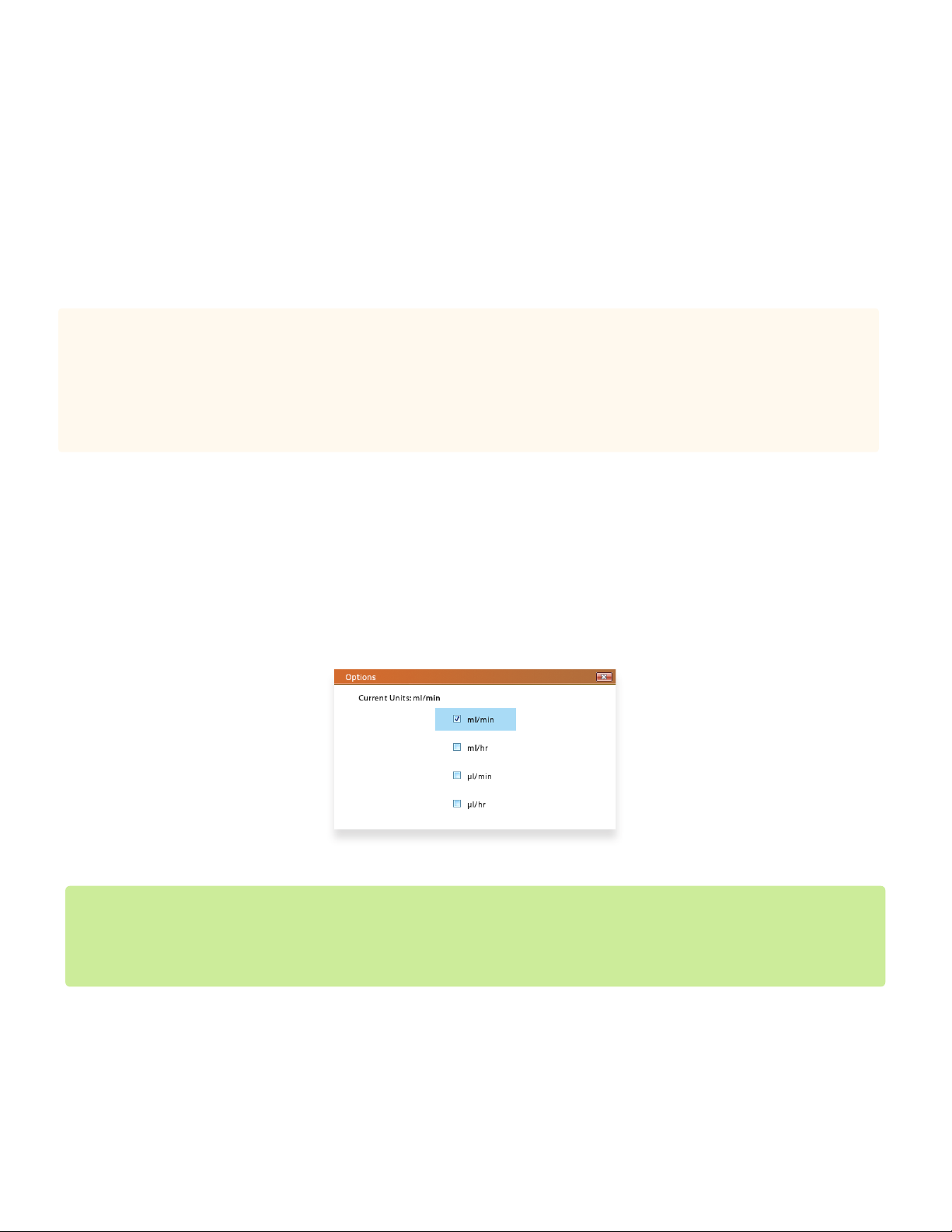
Flow-Rate Units
Tapping the Options button opens a screen that allows ow-rate units to be set. The ow-rate unit determines which unit of
volume and time will be used for the Volume and Rate elds for all of the steps. This setting in Multi-Step Mode also changes
the units for Basic Mode.
Important Note:
Even if the units have changed, the values within the Volume and Rate elds will not change, which will result in signicant changes
in the ow rate and volume transferred. Additionally, the min/max limits for these elds will also change, so if the current values for
volume and rate exceed the new limits, they will be adjusted to be within the limits.
Multi-Step Mode Options screen
The ow-rate units determine which units of volume and time will be used for the Volume and Rate elds. It also determines
the units for the Priming/Bolus Rate. This setting in Basic Mode also changes the units for Multi-Step Mode.

18
Saving Run Parameters
The Fusion 200-X is capable of both infusion and withdrawal. On Fusion 200-X systems, an Infusion/Withdrawal toggle button
should appear to the right of the Volume eld. The text and arrow direction on the button indicates the mode that is currently
set and direction that the pusher block will move upon starting the run. Tapping the button will switch between the two modes.
All of the current settings in Basic Mode can be saved for future use. The
name can be any combination of the alphanumeric characters, up to a
max of eight characters. If a name already exists in memory, the user will
be asked to overwrite the previous method. If the user enters a unique
name or selects “Yes” to the overwrite question, the settings will be saved
to the overwrite question, the settings will be saved to the pump, and the
screen will return to the Basic Mode main screen. If the user selects “No”
to the overwrite question, the screen will return to the Save As name eld
for the user to edit the name. The Fusion series pumps can store up to a
maximum of 20 dierent methods. Save Run Settings screen
Save Run Settings screen
Options

19
Options
Priming allows for the user to temporarily run the pump to remove dead/empty volume in the syringe needle or tubing prior
to running the experiment.
The rate at which priming occurs is set in the Priming/Bolus Rate eld. The value entered can be any integer or decimal
within the limits for the syringe. The min/max ow rate limits can be found in the orange bar at the top of the screen when the
Priming/Bolus Rate eld is selected. Any entered value beyond these limits will be automatically adjusted to the minimum or
maximum limit, whichever is closer. The total number of decimal places is limited to four.
The units for the Priming/Bolus Rate are determined by the Flow-Rate Units setting in Options. Adjusting the units will aect
the min/max limits for the Priming/Bolus Rate eld.
To enter priming mode on Fusion pumps, press and hold the Start key while in the main screen of Basic Mode.
Caution:
Flow rate is often set for the needs of the experiment; however, users should be aware that setting high ow rates, especially for
viscous uids, may require high linear force beyond the limits of the pump which may cause the pump to stall out. Additionally, high
ow rates can exert tremendous pressure within a syringe that may cause glass or plastic syringes to burst. In the case of
high-pressure experiments, users should consider using Chemyx Stainless-Steel Syringes and the high-pressure Chemyx
Nexus 6000 pump.
Example:
To set a delay of 1 min and 30 seconds, press the “1” key, then the decimal key, and nally the “3” and “0” keys. To set a delay of 45
seconds, press the decimal key, then the “4” and “5” keys.
Start-Time Delay
The Delay eld represents the amount of time (in minutes and seconds) to delay starting the pump after pressing the Start
button.
When entering this value with the numeric keypad, the decimal key is used to indicate the separation between minutes and
seconds. The rst two values entered will be minutes unless a zero is the rst value or a decimal is entered, the occurrence of
which causes the next values to be in seconds.
To remove the delay, simply press the clear key (C) or set the time to zero.

20
Multi-Step Mode is used for more advanced applications that may require numerous steps, multiple dierent volume and rate
settings, step looping, or ramping rates.
The Multi-Step Mode screen can be reached by tapping on the Multi-Step icon on the Mode Selection screen.
The pump can only be started in Multi-Step Mode when the Multi-Step Mode screen is showing. This also holds true for
computer control of the pump through a serial connection; the pump must be switched to the Multi-Step Mode screen on the
pump interface rst.
Multi-Step Mode
Setup
Syringe Selection
In Multi-Step Mode, the left side of the screen shows a list of
selectable items. The rst (topmost) item in this list is Setup. Tapping
Setup will take users to the Multi-Step Method Setup screen, where
the syringe inner diameter (ID), total number of steps, number of
loops, and ow-rate units can be set.
Syringe selection for Multi-Step Mode works in much the same manner as seen in Basic Mode.
Changes in the syringe ID will aect the min/max values for the Volume eld in all steps. However, unlike Basic Mode, importing
a syringe from the Syringe Library will not change the volumes in each step to the volume of the syringe unless they exceed the
volume limits of the new syringe. All values in each step that are outside these new limits will be adjusted to be within the limits.
Multi-Step Mode Setup screen
Tip:
Because changing the values of the syringe ID may possibly change the values and units for volume and rate, selecting a syringe or
entering the syringe ID should always be the rst step when setting up a run.
This manual suits for next models
2
Other Chemyx Medical Equipment manuals


