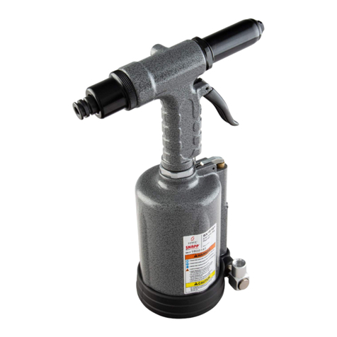
Cherry Aerospace G715A User manual

ORIGINAL INSTRUCTIONS
G715A
Pneumatic-hydraulic Riveter
1224 E. Warner Ave
Santa Ana, CA 92705
www.cherryaerospace.com

DESCRIPTION
The Cherry G715A Pneumatic-Hydraulic
Riveter is designed specifically for the most
efficient installation of Cherry Rivets. It weighs
only 4 lbs. and can be operated in any position
with one hand.
The G715A Riveter is 10-5/8"high, has a 1-
1/8" stroke and generates a minimum of 1400
lbs. of pull on 90 to 110 psi of air pressure at the
tool. See chart on following page for tool
capacity.
PULLING HEADS
Pulling heads are not furnished with this tool but must be ordered separately.
In ordering heads be sure to specify the shank diameter and head style
(universal or countersunk) of the rivets to be installed.
The following pulling heads will fit directly on the G715A Riveter:
G6H Series .... For installing 100, 200, 300 and 500 Series Knob Stem Cherry Rivets.
H80 Series ..... For 600, 700 and 800 Series High-Clinch Cherry Rivets.
H615 Series ... For 2000 Series Locked Spindle, Flush Fracturing Cherrylock Rivets.
H9015 Series . For 9000 Series Serrated Stem Cherry Rivets.
INSTALLING PULLING HEADS ON RIVETER
1. Engage threads of pulling head inside nose fitting (1)
and turn head clockwise until the threads bottom out.
2. Tighten jam nut to lock pulling head in desired position.

TOOL CAPACITY CHART: The numbers shown in the rivet columns below are the maximum grip
length that can be installed with this tool. Dashes indicate sizes which cannot be installed in any grip
length.
CHERRY
RIVETER
MODEL
MS STYLE CHERRY RIVETS
(MS20600)
SELF-PLUGGING PULL-THROUGH
ALUM. MONEL ALUM. STEEL
MONEL
9157
9163 9156
9162 9563 9562 9117
9127 9116
9126 9517 9516
SERRATED
STEM
PULLING
HEAD
RIVET
DIAM.
*
UNIV.
HEAD
CTSK.
HEAD UNIV
HEAD CTSK.
HEAD UNIV.
HEAD CTSK.
HEAD UNIV.
HEAD CTSK
HEAD
-4 ALL ALL ALL ALL ALL ALL ALL ALL
-5 ALL ALL - - ALL ALL - -
-6 16 18 - - - - - -
G715A
H9015
-8 - -
* Rivet diameters shown apply to either knob or serrated stem rivets. Grip lengths shown apply only to knob stem since all lengths of serrated stem rivets can
be installed by cycling tool as many times as necessary.
MAINTENANCE AND REPAIR
The G715A Riveter has been manufactured
to give maximum service with minimum care.
In order that this may be accomplished, the
following recommendations should be
followed.
1. The hydraulic system should be full of oil
and free from air at all times.
2. Keep excessive moisture and dirt out of the
air supply to prevent wear.
3. Do not pound on the rear of the tool head to
force rivets into holes as this will damage
the tool.
4. Make sure the pulling head is correctly and
securely attached.
TO FILL RIVETER WITH OIL
1. Connect the tool to an air line and remove
the cap screw (5) located on the side of the
head.
2. Using a pressure oil can filled with DEXRON
III Automatic Transmission Fluid, Type A (no
substitute), force the fluid into the head until
filled. It may be necessary to turn tool upside
down to insure head is filled with fluid.
3. Replace the cap screw, cycle the trigger
several times and then repeat steps 1 and 2
above.
4. To insure the positive removal of ALL air from
the hydraulic system, we recommend the
use of Cherry Air Bleeder No. 700A77.

SAFETY WARNINGS
•Approved eye protection should be worn when operating, repairing, or overhauling this tool.
•Do not use beyond the design intent.
•Do not use substitute components for repair.
•Any modification to the tool, pulling heads, accessories or any component supplied by
CHERRY® Aerospace, or their representatives, shall be the customer’s entire
responsibility. CHERRY® Aerospace will be pleased to advise on any proposed modification.
•The tool must be maintained in a safe working condition at all times and examined at
regular intervals for damage.
•Before disassembling the tool for repair, refer to the maintenance instructions. All repairs
shall be undertaken only by personnel trained in CHERRY® Aerospace installation tools.
Contact CHERRY® Aerospace with your training requirement.
•Always disconnect the air line from the tool inlet before attempting to service, adjust, fit or
remove any accessory.
•Do not operate the tool when it is directed at any person.
•Ensure that the vent holes do not become blocked or covered and that air line
hoses are always in good condition.
•Excessive contact with the fluid should be avoided to minimize the possibility of rashes.
Care should be taken to wash thoroughly.
•Operating air pressure should not exceed 110 psi (7,6 bar).
•Do not operate the tool without pulling head in place.
•Do not operate the tool unless the handle base (26) is fully secured by the base cover (28) and
retaining rings (27 & 29).
•All retaining rings, screwed end caps, air fittings, trigger valves and pulling heads should
be attached securely and examined at the end of each working shift.
•Do not pull rivet in the air.
•The precautions to be used when using this tool must be explained by the customer to
all operators. Any question regarding the correct operation of the tool and operator safety
should be directed to CHERRY® Aerospace.
•Do not pound on the rear of the tool head to force rivets into holes as this will damage the
tool.
•Do not depress the trigger while disconnecting the air bleeder and replacing the cap screws
(5) when bleeding the tool.

PARTS LIST
FOR THE G715A RIVETER
REP
NO. PART
NUMBER DESCRIPTION QTY.
REQ.
1. 715B34 Nose Fitting 1
2. P838 O-Ring, 6865-110 (No subs.) 4
3. P721 0-Ring, 1/16 x 5/8 x 3/4 1
4. 715D12 Head Cylinder 1
5. P573 Button Hd. Cap Screw 1
6. P572 Stat-O-Seal, 600-001-10 1
7. 715B32 Head Piston 1
8. P568 O-Ring, 3/32 x 5/8 x 13/16 2
9. P1004 Back-Up Ring, MS28782-114 1
10. P-269 O-Ring 1
11. 715B43 Cap 1
12. P832 O-Ring, 9250-010 (No subs.) 1
13. 700A22 Gasket 1
14. P27 Soc. Hd. Cap Screw, 8-32 a 1/2 4
15. 703A11 Handle 1
16. P223 O-Ring, 1/16 a 5/32 x 9/32 1
17. 703A33 Trigger Assembly 1
18. P115 Back-Up Ring, MS28782-8 2
19. P727 O-Ring 1
20. 700B93 Packing Plug 1
21. P731 Back-Up Ring, MS28783-13 2
22. P730 Quad Ring 1
23. 700B6
A
ir Piston 1
24. P737 Conelok Nut, 1/4-20 1
25. P725 O-Ring, 1/16 x 3 x 3-1/8 1
26. 700B4 Handle Base 1
27. P735 Retaining Ring 1
28. 700B5 Base Cover 1
29. P736 Retaining Ring 1
30. P734 Retaining Ring 1
31. 700B7 Power Cylinder 1
32. P833 0-Ring, 9250-118 (No subs.) 2
33. P739 Back-Up Ring, MS28774-14 1
34. P294 O-Ring, 1/16 x 1/2 a 5/8 1
35. 700A8 Power Piston & Rod 1
36. P653 O-Ring, 1/16 x 9/16 x 11/16 4
37. 700B73 Valve Sleeve 1
38. 700A67 Spring 1
39. P829 0-Ring, 6865-012 (No subs.) 3
40. 700A15 Valve Spool 1
41. P834 O-Ring, 6865-017 (No subs.) 2
42. 700A16 Valve Plug 1
43. 700A17 Muffler 1
44. P279 Retaining Ring 1

For more information
p
lease contact our Technical Services De
p
artment at Tel. 714-850-6022
Seller warrants the goods conform to applicable specifications and drawings and will be manufactured and inspected according to generally accepted practices of
companies manufacturing industrial or aerospace fasteners. In the event of any breach of the foregoing warranty, Buyer’s sole remedy shall be to return defective
goods (after receiving authorization from Seller) for replacement or refund of the purchase price, at the Seller’s option. Seller agrees to any freight costs in
connection with the return of any defective goods, but any costs relating to removal of the defective or nonconforming goods or installation of replacement goods
shall be Buyer’s responsibility. SELLER’S WARRANTY DOES NOT APPLY WHEN ANY PHYSICAL OR CHEMICAL CHANGE IN THE FORM OF THE
PRODUCT IS MADE BY BUYER.
THE FOREGOING EXPRESS WARRANTY AND REMEDY ARE EXCLUSIVE AND ARE IN LIEU OF ALL OTHER WARRANTIES AND REMEDIES;
ANY IMPLIED WARRANTY AS TO QUALITY, FITNESS FOR PURPOSE, OR MERCHANTABILITY IS HEREBY SPECIFICALLY DISCLAIMED AND
EXCLUDED BY SELLER. THIS WARRANTY IS VOID IF SELLER IS NOT NOTIFIED IN WRITING OF ANY REJECTION OF THE GOODS WITHIN
ONE (1) YEAR AFTER INITIAL USE BY BUYER OF ANY POWER RIVETER OR NINETY (90) DAYS AFTER INITIAL USE OF ANY OTHER
PRODUCT.
Seller shall not be liable under any circumstances for incidental, special or consequential damages arising in whole or in part from any breach by Seller, AND
SUCH INCIDENTAL
,
SPECIAL
,
OR CONSE
Q
UENTIAL DAMAGES ARE HEREBY EXPRESSLY EXCLUDED.
TROUBLE SHOOTING
1. Check air line for correct pressure at the
tool. It must be 90 to 110 psi.
2. Check tool for lack of hydraulic fluid (see oil
filling instructions).
3. Check for oil leakage.
a. Oil leaking around the cap screw (5) in
the head indicates that the screw is loose
or the washer gasket (6) needs replacing.
b. If oil should leak through the by-pass
hole at the base of the handle (15) the
O-Rings (32) are worn or damaged.
c. Oil leaking from the front of the nose
fitting (1) indicates that O-Rings (2) are
worn or damaged.
d. If head is taken apart for repair check
all O-Rings and carefully clean all parts
before reassembling. Be sure to make
any replacements with the exact O-Rings
shown in the parts list to insure that the
correct material and hardness is used.
4. Check valve for air leakage. If air is
escaping, remove retaining ring (44) and
muffler (43). Insert a 5/16-18 threaded rod
or bolt into end of valve plug (42) and pull
it out. Using the same procedure pull out
spool (40). Replace O-Rings (39 & 41) and
reassemble.
Note: It should never be necessary to remove
the valve sleeve (37) unless the air supply has
become so badly contaminated that the ports
in the sleeve are plugged up. If this
unlikelihood should occur, carefully remove
spring (38) from its groove, using extreme
caution not to distort the coils of the spring.
Remove sleeve (37), clean thoroughly,
replace O-Rings (36) and reassemble,
making sure that spring (38) is seated in its
groove correctly, otherwise valve will not
function.
5. Check movement of piston (7). If it does not
move freely or is slow in operation:
a.O-Rings (8) may be damaged and require
replacement.
b.Piston (7) may be mechanically locked
due to damaged parts.
c.Power piston may be held off its seat on rod
(35) allowing oil to by-pass. Drain tool, flush
thoroughly and refill with fresh oil.
d.Muffler (43) or air filter inside spool (40) may
be plugged with dirt. Clean them
thoroughly with normal solvent and back-
blow with compressed air.
NOTE: We recommend the purchase of a
G715KS Service Kit which contains
various gaskets, O-Rings, washers
and similar parts likely to need replacing
in time.
WARRANTY
TM-G715A
Rev.: C
DCR# 10-1064
Date: 09-29-10
Supplier’s Federal Identification Code: 11815
© 2007 CHERRY® AEROSPACE
LOCTITE
®
is a registered trademark of Henkel Corporation
DEXRON®is a registered trademark of GM corporation.
PARKER®is a trademark of Parker Hannifin Corporation
Table of contents
Other Cherry Aerospace Rivet Tools manuals

Cherry Aerospace
Cherry Aerospace G902 User manual

Cherry Aerospace
Cherry Aerospace CHERRYMAX G749A User manual
Cherry Aerospace
Cherry Aerospace G-689 User manual
Cherry Aerospace
Cherry Aerospace CherryMAX G747 User manual
Cherry Aerospace
Cherry Aerospace CherryLOCK G685B-S User manual
Cherry Aerospace
Cherry Aerospace G700 User manual
Cherry Aerospace
Cherry Aerospace G702A User manual
