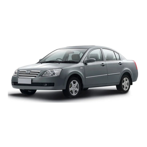
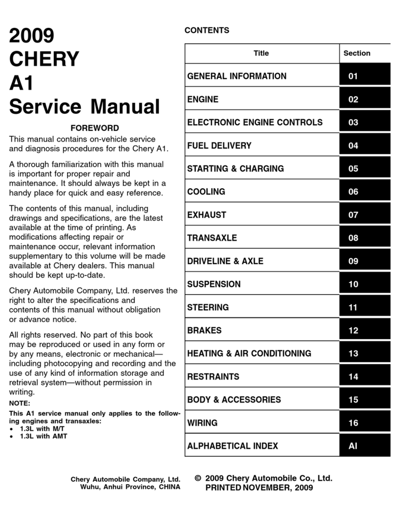
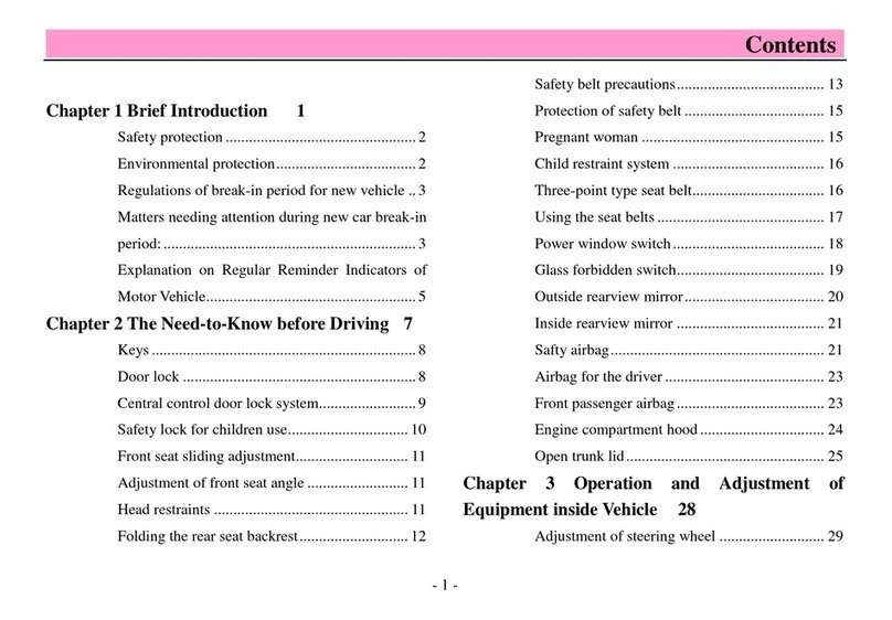
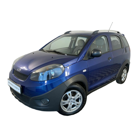
Chery A113 User manual

MaintenanceManualofCheryA113
(Chassis)
CheryAutomobileCo., Ltd

CONTENT
Chapter1BrakeSystem.................................................................................................................4
I. SystemCheckingParameters..................................................................................................4
1. Checkbrakedisc.....................................................................................................................4
2. Thickness checking.................................................................................................................4
3. Checkingofbrakefrictionlining thickness............................................................................4
4. Checkingofbrakediscrun-out..............................................................................................4
II. Removal/Installationand OverhaulofFrontBrakeandBrake Calliper...........................5
1. SystemStructuralDiagram.....................................................................................................5
2. Preparations............................................................................................................................6
3. Notices....................................................................................................................................6
4. RemovalandOverhaul...........................................................................................................6
III. Removal/Installationand OverhaulofRear Brake..........................................................10
1. SystemStructuralDiagram...................................................................................................10
2. Preparations..........................................................................................................................10
3. Notices..................................................................................................................................10
4. RemovalProcedure..............................................................................................................11
4. InstallationProcedure...........................................................................................................13
IV. AdjustmentandReplacementofHandbrake....................................................................14
1. SystemCompositionIllustration..........................................................................................14
2. Preparations..........................................................................................................................14
3. Notices..................................................................................................................................14
4. Removal/InstallationProcedure...........................................................................................14
Chapter 2 AdjustmentofSuspensionSystemandFour-WheelAlignment...............................18
I. Removal/Installationand OverhaulofFrontAxleandSuspension...................................18
1. SystemStructuralDiagram...................................................................................................18
2. Preparations..........................................................................................................................20
3. Notices..................................................................................................................................20
4. Removal/InstallationProcedure...........................................................................................20
4.1RemovalofShockabsorberassembly............................................................................20
4.2RemovalofControlArmAssembly...............................................................................21
4.3RemovalofFrontAxle Assembly...................................................................................22
5. InstallationProcedure...........................................................................................................24
II. Removal/Installationand OverhaulofRearAxleandSuspension...................................25
1. SystemStructuralDiagram...................................................................................................25
2. Preparations..........................................................................................................................26
3. Notices..................................................................................................................................26
4. Removal/InstallationProcedure...........................................................................................26
4.1RemovalofShockAbsorberAssemblyandShockAbsorberSpring.............................26
4.2Cross StayAssembly......................................................................................................27
4.3RearTrailingArmAssembly..........................................................................................27
4.4.RemovalofRearAxle Assembly...................................................................................28

5. InstallationProcedure...........................................................................................................29
III.AdjustmentofFour-WheelAlignment...............................................................................30
1. AdjustmentofFrontWheelToe-In......................................................................................30
2. AdjustmentofFrontWheelCamberAngle..........................................................................30
3. AdjustmentofCasterAngle andKingpinInclination..........................................................30
4. AdjustmentofRear-WheelAlignmentParameters..............................................................31
IV. Tire InstallationandAir PressureAdjustment.................................................................31
1. InstallationofAirValve.......................................................................................................31
2. Tire Assembling...................................................................................................................31
3. Tire Inflation.........................................................................................................................32
4. InstallationofWheeland Tire Assembly.............................................................................32
5. Tightening Method ofWheelBolts......................................................................................32
6. InstallationofDecorative Cover...........................................................................................32
Chapter3Removal/InstallationandOverhaulofSteeringSystem............................................33
I. Removal/InstallationofSteeringGear..................................................................................33
1. SystemCompositionIllustration..........................................................................................33
2. Preparations..........................................................................................................................34
3. Notices..................................................................................................................................34
4. Removal/InstallationProcedure...........................................................................................35
5. InstallationProcedure...........................................................................................................36
II. Removal/InstallationofSteeringColumn...........................................................................37
1. SystemCompositionIllustration..........................................................................................37
2. Preparations..........................................................................................................................37
3. Notices..................................................................................................................................37
4. RemovalProcedure..............................................................................................................38
5. InstallationProcedure...........................................................................................................43
III.AdjustmentofSteeringGearClearance............................................................................44
IV.AdjustmentofPowerSteeringSystem................................................................................44

Chapter1BrakeSystem
I. SystemCheckingParameters
1. Checkbrakedisc:
Thefrictionsurface ofbrake discshouldbe flatandhasnoapparentgrooves;otherwise,brakediscshouldbe
replaced.
2.Thicknesschecking
Thestandardthickness offrontdisc(ventilation disc)is17 mmwithitsoperatinglimit of15 mm;when
exceedingtheoperating limit,the frontdisc shouldbe replaced.
3. Checkingofbrakefrictionliningthickness
Standardthickness offrontbrakelining shall be 10 mm,applicationlimitshall be1 mm, and the remaining
thickness oflimitbrakepadthickness shall be notlessthan1mm.
Standardthickness ofrearbrakelining shallbe 5 mm,application limit shallbe1 mm,and the remaining
thickness oflimitbrakepadthickness shall be notlessthan1 mm.
4. Checkingofbrakediscrun-out
Usedialgauge tocheckthe face runoutofbrake disk, theapplicationlimitoffrontdiskshallbe 0.03mm, the
application limit ofreardiskshall be0.03mm,otherwise replace it.
Importantnotice:
Aftercompletion ofreplacing friction liningorbrake disk,applythe brake forseveraltimestoenable breaking-in
betweenbrakelining andbrake disk.Alwaysensure safety!
Afterreplacing brakelining, checkbrake fluidleveltoensure itisbetweenMINandMAX.

II. Removal/InstallationandOverhaul ofFront BrakeandBrake Calliper
1. SystemStructuralDiagram
StructuralDiagramofFrontBrakeAssembly
(1)Brakedisc positioningbolt(2)Brake disc
(3)Wheelhub bearingunit;(4)ABSspeedsensorplug
(5)Dustcover(6)Steeringjoint
(7)Fixing bolt (8)Friction lining
(9)Frictionlining thickness sensorplug(10)Brakebracket
(11)Brake calliperassembly(12)Fixing bolt

2.Preparations
Tools: Ratchetwheel,ratchetlever, 13#, 14#,16#,18#, 19#,8#,
30#socket, 10#,13#,14#,16# ring wrench, vice,
torquewrench,measure ruler..
Accessories: brake fluid
3.Notices
3.1Pleasewearnecessarylaborprotectionsuppliestoavoid
accidents.
3.2Thebrakeliquidisonetoxicliquid.Ineventofcontactwiththe
skinoreyesduetocarelessness,flushwithagreatamountofwater
andifnecessarycall formedicaltreatmenttimely.
3.3Thescrappedbrakeliquidshouldbeaccommodatedinthe
container.It sprohibitedtodrainit intothesewagesystemorstack
withotherhouseholdgarbage.
3.4Donotdepress thebrakepedalnormovethevehicleduringthe
removal/installationoperation.
3.5Donotmakethefrictionliningorbrakedisccomecontactwith
the oil substances, whichwill impairthebraking effects.
4.RemovalandOverhaul
4.1Removetheprotectivecoverfromthetirerimwithslotted
screwdriver.
4.2Removethetirefixing nutswith19#torquewrenchorvehicle
attachedtoolandremove thetire.
Torque:110±10Nm.
4.3Liftthevehiclewithelevator.
4.4Removethe 2nuts(upperand lower) from
the brakecalliperand steering jointwith18# wrench.

4.5Removethe nutsfrombrake hosewith13#wrench.
Notice:Thebrakeliquidisonetoxicliquid.Donotsplashthebrake
liquidtotheclothesorskinduringthe removalofthe brake hose.
Torque:16±3Nm.
4.6Pulloutthe brake disc withhand.
4.7Measurethethickness offriction lining.Ifbelow3mm,replace
timelyinpairs.
4.8Removethe brake calliperandbrake pumpwith14# wrench.
4.9Removethedustproofsealandcheckforthedamageofthe
dustproofseal.Ifnecessary,renewthedustproofseal.Cleanthe
contactsurfaceofthebrakepistonand applywithonefilmof
silencing grease.
Notice:It'sprohibitedtomakethedustproofsealcomecontactwith
thesilencing grease, whichwillcausetheswelling ofthedustproof
seal.

4.10Removethepiston.Prepareonewoodboardtoholdthepiston
and place thewoodboardbetweenthepistonandthewallofthe
brakecalliper.Press outthepistonwiththecompressedaircarefully
throughtheconnectingbore. Place theguardplate(suchashard
wood)atthe notchofthebrake callipertoprotectthe piston.
Notice:Donotholdthepistonwithfingers –dangerofclamping!
Thebrakecalliperpiston isprohibitedfromremovalatwilland
shouldberemoved/installedonlybyprofessionalsorunderthe
guidance oftheprofessionals.
4.11Checktheguidesleeve.Theguidesleeveshouldmove
smoothlyand freelywhenpushedwithhand.Replacetheguide
sleeveineventofjammingorstiffness.Notice:Applythe
lubricating greaseontotheguide sleeve during assembling.
4.12Remove the sealringcarefullywiththeplastic needle,cleanthe
brakecylinderand componentswithalcoholandblowdrywith
compressedair.Carefullycheckthesurfacesofbrakecylinder,
piston,and flange. It sprohibitedtoconductthemachiningprocess
onthe brake cylinderand piston.
4.3Installationofbrakebranchpump:Applyonefilmofbrake
cylindercreamontothecylinderbody,plunger,and sealsleeve.
Attachthesealring ontothecirculargrooveattherearofthebrake
cylinder.Attachthedustproofsealringontothefrontcirculargroove
andpress itincompletely.

4.14Thearea betweenthedustproofsealringandthebrakeclamp
housingmustbekeptdry.Itshouldbekeptawayfromthebrake
cylindercreamorthebrakeliquid,inordertoensurethecorrect
position ofdustproofsealring.
4.15Securethebrakepiston withthereinforcementpartsavailable
inmarketand press it ontothedustproofsealring slightly.Blowthe
dustproofsealringwithcompressedair(upto3.0bar)toattachthe
piston ring ontothe piston.
Notice:Dipthe dustproofsealring and piston withbrake
liquidtofacilitate the passingofthe sealring.
4.16(Checkingofbrakedisc)Checkthethicknessofbrakedisc.
Replace the brakedisc ifthe thickness isless thanthe minthickness.
Notice:Thetwobrakediscsatthesameaxleshouldbereplacedata
time.Thefrictionliningsmustbereplacedfollowing the
replacementofthe brakediscs.
4.17Checkthemaxrun-outoftheend surfaceofbrakediscwith
dialgage.Ifabove0.03mm,replace it.(Providedthatthebrakedisc
thickness isguaranteed,itmayconductthepropermachiningto
meetwiththe maxrun-out.)
4.18InstallationofotherportionswithreferencetotheRemoval
Procedure.

III. Removal/InstallationandOverhaul of RearBrake
1. SystemStructuralDiagram
1. Rearbrake assembly2.Brake drum
3. Rearwheelhubbearing assembly4.Oilseal
5. Endcap6.Bolt
7. Rearwheelsensor8.Rearbrake hoseretainingclip
9. Dual-portpipe clip10. Tierod
11.Rearshoe pressurespringplate12.Rearshoepressure spring
2.Preparations
Tools:
Ratchetwheel,ratchetlever,10#,19#, 32#socket,10# ringwrench,
vice, torque wrench,slottedscrewdriver.
Accessories:brakefluid
3.Notices
3.1Pleasewearnecessarylaborprotectionsuppliestoavoid
accidents.
3.2Thebrakeliquidisonetoxicliquid.Ineventofcontactwiththe
skinoreyesduetocarelessness,flushwithagreatamountofwater
andifnecessarycall formedicaltreatmenttimely.
3.3Thescrappedbrakeliquidshouldbeaccommodatedinthe
container.It sprohibitedtodrainit intothesewagesystemorstack
withotherhouseholdgarbage.
3.4Donotdepress thebrakepedalnormovethevehicleduringthe
removal/installationoperation.
3.5Donotmakethefrictionliningorbrakedisccomecontactwith
the oil substances, whichwill impairthebraking effects.

4.RemovalProcedure
4.1Removetherearwheels(see theremovalprocedureoffront
wheels).
4.2Removetwopositionboltsfromthebrakedrumwiththecross
screwdriver.
4.3Removethe bearingdustcapwithslottedscrewdriver.
4.4Vibratethebrake drumtoremove it.
4.5Observetherearbrakingstructure.
4.6Ifit snecessarytocheckthebrakedrumbearing,removethe
locknutsshowninthefigurewith30# socketand torquewrench
andremove the brake drumbearing.
Torque:250±10Nm

4.7Removethe handbrakecable withcalliper.
4.8Removethe upperreturntensionspring withcalliper.
4.9Removethe lowerreturntensionspringwithcalliper.
4.10Depress thespringstripofthebrakeshoepositioningtierod
withcalliperand thenrotateclockwiseorcounterclockwisefor90°
toremove twobrake shoepositiontie rods.
4.11Pullouttwobrake shoes.

4.12Remove thetensionspringtoseparatethebrake shoe.
4.13Intheeventofdetectionofover-tightrearbrake, itmayadjust
the lengthofthepushrod:Rotate clockwise toeliminate the friction.
4.14Removethethreeboltsshowninthefigurewith10#ring
wrench.
4.15Removethebranchpumpandbreakitdownforchecking of
intactness.
4.InstallationProcedure
Refertoremovalprocedures.
Bolts
Removethis
tension spring.

IV. AdjustmentandReplacement ofHandbrake
1. SystemCompositionIllustration
1.Handle2.Fixingbolts3. Cable4, 5.Left/Rightrearwheelcable
2. Preparations
Tools:Ratchetwheel, ratchetlever, 10#,13#,14#, 16#socket,10#
13#,14#ringwrench,vice, torque wrench,slottedscrewdriver.
3. Notices
3.1Please wearnecessarylaborprotectionsuppliestoavoidaccidents.
3.2Duringtheremoval/installation ofthespringparts,enough cautionsshouldbetakentopreventtheejection
ofsuchpartsfromcausingbodyinjuries.
3.3Theremoval/installationatthevicinityoftheexhaustpipemustbeconductedonlyafterthetemperatureof
theexhaustpipe isloweredtonormaltemperature soastopreventscald.
4.Removal/InstallationProcedure
4.1Withreferencetotheremoval/installationoftherearbrake,
loosenthehandbrake cable oftherearwheels.
T
oleft
rear
brake
assembly
Toright
rear
brake
assembly

4.2Removethe handbrakeclipwithpriers.
Notice:It sunderthe rearwheels.
4.3Removethefixingbracketboltsofthehandbrakecableshown
belowwith8#ringwrench.
Torque:9~12 Nm
4.5Pryouttheprotectivecoveratthehandbrakeandgearposition
withslottedscrewdriver.

4.6Removeall fixing screwsfromthesecondaryinstrumentpanel
assemblywithringscrewdrivertoremovethesecondaryinstrument
panelassembly.
4.7Removethe handbrakeadjustmentnutswith10# wrench.
4.5Loosenthe twohandbrake cableswithhand.

4.9Pulloutthe handbrake cable fromtheunderside ofthe vehicle
body.
Notice:Removethehandbrakecableatanothersideinaccordance
withthe same method.
4.10 (Handbrake adjustment) The lengthofthe handbrakecable
equippedonthismodelisdesignedtobe the fixedlength.Toadjust
the handbrakeeffects,refertothepart “removalofrearbrake”.The
adjustmentofthe ejectorrodlength(clockwise forlooseness and
counterclockwisefortightness)canachievethe handbrake
adjustment.
4.11Theinstallation procedureshouldbeconductedwithreference
tothe removalprocedure.
Rotate thisplace

Chapter2AdjustmentofSuspensionSystemand Four-Wheel
Alignment
I. Removal/InstallationandOverhaul ofFront Axle andSuspension
1. SystemStructuralDiagram
ThefrontaxleofCheryS21 modeladoptsthesplit steeringdriveaxle, withMacPherson independent
suspension.Theupperend ofthesuspension isconnectedwiththevehiclebodyasthelowerendisconnected
withthesecondaryvehicleframe.ThefrontMacphersonsuspensionundertakesthedualfunctionsofdriving
andsteering.Subframeconnectswithvehiclebodyviaelasticelement, whichimprovesdivingstabilityandride
comfort.
StructuraldiagramofFrontAxle and SuspensionSystem

1
Nut 9 Nut 17
Nut
2
Gasket 10
Leftcontrolarm 18
Nut
3
RubbergasketI 10
Rightcontrolarm 19
Bolt
4
RubbergasketII 11
Nut 20
Bolt
5
Leftpropellingrodweldmentassembly 12
Secondaryvehicleframe 21
Clamp
5
Rightpropelling rod weldmentassembly
13
Frontstrutassy. 22
Rubberbush
6
Nut 14
Nut 23
Bolt
7
Bolt 15
Frontconnectingrod assy. 24
Bolt
8
Bolt 16
Frontstabilizerbar 25
Bolt
CompositionListforFrontAxleand SuspensionSystem

2. Preparations
Tools:8#, 15#,18#,19# socket;10#,13#,15# wrench.
3. Notices
2.1Please wearnecessarylaborprotectionsuppliestoavoidaccidents.
2.2Whencarryoutmaintenance and repairtochassis,pleasenotethatwhetherthesafetylockoflifting
machine islocked.
2.3Whencarryoutremoval/installationtoshockabsorberspring,preventspringejectionfrombeing injured.
2.4It sprohibitedtoconducttheweldingandcorrectiononthebearing componentsofthewheelsuspension
and the guiding componentsofthe wheels.
2.5During theremovalofthechassiscomponent, renewthe self-locknutsandrustednutssoastoguarantee the
safety.
4.Removal/InstallationProcedure
4.1Removalofshockabsorberassembly
4.1.1Removethetirefixingnutswith19#socketorvehicle attached
wrenchtoremovethe tire(take leftside forinstance).
Torque:110±10 Nm
4.1.2RemovetheABSpipeline fromthe fixingseatwithhand.
4.1.3Removethefixingboltsofsteering jointandshockabsorber
with18# socket.
Torque:110±10Nm
Table of contents
Other Chery Automobile manuals

Chery
Chery Tiggo 5 T21 User manual

Chery
Chery Automobile User manual
Chery
Chery QQ6 User manual

Chery
Chery Tiggo 2009 User manual
Chery
Chery A3 User manual

Chery
Chery TIGGO User manual

Chery
Chery M16 Arrizo 7 2014 User manual
Chery
Chery A5 2007 Service manual
Chery
Chery Karry series User manual
Chery
Chery V5 User manual
