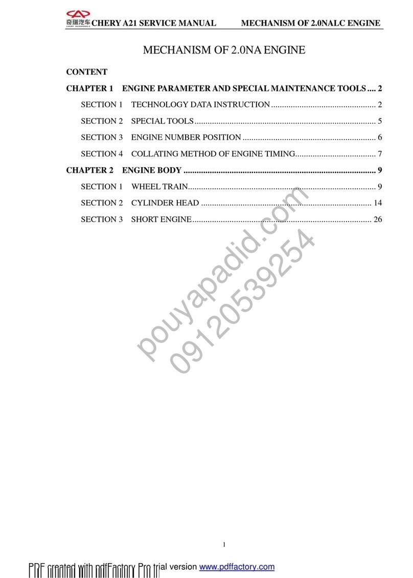
Chery QQ User manual

CheryQQServiceManual MechanicalPartofSQR472Engine
1
SQR472 Engine
Service ManualforMechanicalPart)
After-salesDepartment ofCheryAutomobile SalesCo.,Ltd.

CheryQQServiceManual MechanicalPartofSQR472Engine
1
CONTENTS
Chapter1 ReadingInstruction......................................................................................................................................2
1)ReadingmethodofMaintenance Instruction............................................................................................................2
2)MeaningofMarksandAbbreviations......................................................................................................................3
3)SpecialMaintenance Tool.........................................................................................................................................4
Chapter2 Disassembly,Assemblyand Maintenance....................................................................................................6
1)TimingBelt...............................................................................................................................................................6
1. StructureDiagram.............................................................................................................................................6
2. Disassembly......................................................................................................................................................7
3. Installation......................................................................................................................................................10
2)Camshaft.................................................................................................................................................................13
1. StructureDiagram...........................................................................................................................................13
2. Disassembly....................................................................................................................................................14
3. Installation......................................................................................................................................................16
4. RoutineInspection ofValve............................................................................................................................19
3)CylinderHead.........................................................................................................................................................22
1. StructureDiagram...........................................................................................................................................22
2. Disassembly....................................................................................................................................................23
3. RoutineInspection..........................................................................................................................................23
4)WaterPump............................................................................................................................................................29
1. StructureDiagram...........................................................................................................................................29
2. Disassembly....................................................................................................................................................29
3. Cleanup...........................................................................................................................................................29
4. RoutineInspection..........................................................................................................................................29
5. Assembly.........................................................................................................................................................29
5)Oil Pump.................................................................................................................................................................29
1. StructureDiagram...........................................................................................................................................30
2. Disassembly....................................................................................................................................................30
3. Cleanup...........................................................................................................................................................30
4. Disassemblyand AssemblyofEngineOil Pump............................................................................................43
4.1 StructureDiagram.................................................................................................................................42
4.2 Disassembly..........................................................................................................................................42
4.3 RoutineInspection................................................................................................................................42
4.4 Installation.............................................................................................................................................44
5. DisassemblyofOil Seal..................................................................................................................................45
5.1 StructureDiagram.................................................................................................................................45
5.2 Disassembly..........................................................................................................................................46
5.3 Inspection..............................................................................................................................................46
5.4 AssemblyofOil Seal............................................................................................................................46
6Assembly..........................................................................................................................................................46
6)Crank ConnectingRodMechanism........................................................................................................................46
1. StructureDiagram...........................................................................................................................................48
2. DisassemblyofCrankConnectingRodmechanism.......................................................................................48
3. Cleanup...........................................................................................................................................................49
4. RoutineInspection..........................................................................................................................................52
5. AssemblyofCrankConnectingRodMechanism...........................................................................................53

CheryQQServiceManual MechanicalPartofSQR472Engine
2
Chapter3 TableofMainFit Clearance forSQR472 Engine......................................................................................55
Chapter4 TableofMeasurementParametersofSQR472 Engine..............................................................................59
Chapter5 TableofMainFittingTorqueforSQR472 Engine.....................................................................................61
Chapter6 PositionsonSQR472 EnginetobeLubricated..........................................................................................62
Chapter7 PositionsonSQR472 EnginetobeSpreadwithSealant............................................................................65

CheryQQServiceManual MechanicalPartofSQR472Engine
3
Chapter 1.ReadingInstruction
1)ReadingMethodofMaintenanceInstruction
.1 AuxiliaryMaterials
If it isrequiredintheoperationinstructiontopreparetheauxiliarymaterialssuchasspecialtools,tools,measuring
instrumentsandgreaseinadvance,youshouldlistallauxiliarymaterialsrequiredinatablebeforecarrying outeach
operation.
Sincetheordinarytools,lifterandsparepartsareconventionalmaterialsusedinthemaintenance,theyareomitted
here.
.2 OperatingSequence and StructureDiagram
(1)Thediagramofstructureandcomponents,nameofcomponentsandinstallationstatusaresetforthatthe
beginningofeachchapterorsection.
(2)Thenumberinthefigurereferstothedisassemblysequenceofeachcomponent.Thecomponentswhichmaynot
bereusedand thetighteningtorqueareindicatedinthefigure.
Seal Ring
②EngineOilPumpCoverSheet
③EngineOilPumpOuterRotor
④EngineOilPumpInnerRotor
⑤CotterPin
⑥Oil DrainValveSpringSeat
⑦Oil DrainValveSpring
⑧SlideBlock
⑨CrankshaftFrontOilSeal
⑩EngineOilPumpHousing
1 .3 ContentOmittedinthisManual
Thefollowingoperating procedureshavebeenomittedinthisManual,andtheyshouldbecarriedoutintheactual
operation:
(1)Operation relating tothelifterandthesmall-sizedelevator;
(2)Cleaningandwippingofcommon components;
(3)Relevantvisualinspection.
※:C omponentswhichmay
not bereused
Unit:N m(kg cm)

CheryQQServiceManual MechanicalPartofSQR472Engine
4
1 .4 Definitions
Referstoallowedvalueduringinspection,maintenance andadjustment.
Referstothemaximumorminimumvaluethatshouldnotbeexceededduring
inspection,maintenanceandadjustment
Setthestandardvalueforsimplemeasurementtopreventfromitsmeasuring
difficultyandinconsistencytofacts.
Referstothedifferencebetweenmaximumvalueandminimumvalue.
Itcarriesthecasesofdamaging thevehicleandpartssoyoushouldpayattention
totheoperationdescription.
Itrecordstheoperationdescriptionsofcasesaboutperson accident.
2)MeaningofMarksandAbbreviations
Mark OriginalWords Intepretation
RH RightHand RightHand
LH LeftHandLeftHand
FR Front Front
RR Rear Rear
IN Intake Intake
EX Exhaust Exhaust
SAE SocietyofAutomotiveEngineers SocietyofAutomotiveEngineers
API AmericanPetroleumInstitute AmericanPetroleumInstitute
SPECIAL
TOOL SpecialTool SpecialTool
T Torque Torque
Ay Assembly Assembly
S/A SubAssembly SubAssembly
W/ With With
M/T ManualTransmission ManualTransmission
A/T AutomaticTransmission AutomaticTransmission
T/C TurboCharger TurboCharger
Standardvalue
Limit
Reference
Difference
Notice
Warning

CheryQQServiceManual MechanicalPartofSQR472Engine
5
3)SpecialMaintenanceTools:
Outsideview Nameorsymbol Purpose
Enginedisassemblyandinspectionauxiliary
device
Mountontheengineservice
stand
Engineservicestand Disassemblyandassembly
ofengine
Clampholewrenchforcamshafttiming gears
Disassemblyofcamshaft
timinggears
Springbushingpuller AssemblyofcamshaftOil
seal
Valvekeeperremovetool
Auxiliarytools
Assemblyanddisassembly
ofvalvespring retainerlock
Flywheelclamp Assemblyanddisassembly
ofcrankshaftgear
Valveguidepunchpin Disassemblyandassembly
ofValveguide
AxialOil sealreplacingdevice
Oil sealbasedrive

CheryQQServiceManual MechanicalPartofSQR472Engine
6
Outsideview Nameorsymbol Purpose
Piston pinpuller Disassemblyandassembly
ofpistonpin
Embededcombinationoil sealandhelical
gearpuller Installationofoil seal
Crankshaftpulleyholdingtool Disassemblyandassembly
ofcrankshaftpulley
Wrench Disassemblyandassembly
ofcrankshaftdrivengear
Replace valveclearance
adjustmentgasket
Waterpumppulleylockingwrench Assemblyofcoolantpump
Measuring
tools
Feelergauge.Micrometercaliper.Ruler.Dialgauge.Cylindergauge.Caliber.Pressuregauge.Torque
wrenchtorquewrench
Tool Piston ringextractor
Oil EngineOil, adhesive

CheryQQServiceManual MechanicalPartofSQR472Engine
7
Chapter 2.Disassembly,Assemblyand Maintenance
Disassembleorassembletheenginewithroll overstand.
Disassembleorassembletheenginepartson theroll over
stand.
1)TimingBelt
1.StructureDiagram
①Waterpumppulley
②Timingshroud
③Timingbelt
④Torsionaldamper
⑤Timing beltbackplate
⑥Tensionpulley
⑦Camshafttimingpulley
※:C omponentswhichmay
not bereused.
Unit:N m(kg cm)

CheryQQServiceManual MechanicalPartofSQR472Engine
8
2.Disassembly
2.1 Removethewaterpumppulleyastheviewshowing.
Itwill bebetterofdisassemblingwithspecialtool.
Torque:25±1.5 N.m
2.2 DisassemblyofTimingBelt Cover
Torque:6±1N.m
2.3 Disassemblyoftorsionaldamper
Usespecialtoolstopreventthegearring from
rotating.Whendisassemblingthefixingboltsofthe
torsionaldamper,makesurethatthemarksonthe
crankshafttimingpulleymatchwiththetimingmarks
ontheengineoil pump.
2.4 Removethetimingbelt backplate.

CheryQQServiceManual MechanicalPartofSQR472Engine
9
2.5 Disassemblyoftensionpulley
2.5.1 Compressthetopdeadcenteratthefirstcylinder
piston.Afterdisassemblyoftimingcover,pull the
bolt andclockwiserotatethetiminggearwith
wrench.Andthenalignthetimingmarkofcamshaft
timinggearandtheraisedmarkoncamshaftcover;
2.5.2 Screwoffthebolt oftensionpulleyandremovethe
tensionpulley.
2.6 Disassemblyoftimingbelt
Notice:Donotusesharptoolslikescrewdriverduring
disassemblyofbelt.
Notice:Payattentiontothefollowingitemsduringusing
thetimingbelt:
lDonotbendthebelt withsmall angle,ortheriggingin
belt willbreak.
lDonotpollutegreaseandwaterbecausetheusing
expectancyofbeltisshort.
lOnlyclockwiserotatetheengineaftermountingthe
belt.
2.7 Disassemblyofcrankshafttiminggear
TimingMark
TimingMark Clockwise

CheryQQServiceManual MechanicalPartofSQR472Engine
10
2.8 Inspectthetimingbelt carefully,andreplacenewcomponentsunderanyofthefollowingcircumstancesorwhen
themileageisuptotheconditionsofreplacement:
2.8.1 Chapofback-siderubber
2.8.2 Chapofdedendum, chapofseparatedcordfabric.
2.8.3 Wearing,gearmissingandincompletegearofcordfabric.
2.8.4 Abnormalwearingofbelt flank.
2.8.5 Notice:Replacethebelt asanyfollowingsituationoccurs,eventhoughabrasion cannotbefounddirectly:
Thewaterpumpleakswaterout,and requirescontinuinginfusion.If thebelt isspottedwithmuchoilstains,andthe
rubbermaybedamagedduetoexpansion,youshouldreplace thebelt.
Timingbelt modelandtype
Partnumber 372-1007081
Widthofbelt 25.3mm
TensionPulleyofTimingBeltRotatethebolt oftension pulleybracketandhearifit isnoisy;checkthecontacting
surface andlookifit isdamaged.Modelandtypeoftensionpulleyoftiming belt
Partnumber 372-1007030
Width 27.0mm
Outerdiameter φ50mm
Checkiftheoutisdamaged.Timingbelt modeland type
EFType
Item GL, ZL, GS, ZS
Camshafttimingpulleydiameter(mm) φ110.7+0.1-0.2
Camshafttimingpulleydiameter(mm) φ54.65+0.7-0.13
Chap
Chap
Wearing
Abnormal
Gear
Falloff with

CheryQQServiceManual MechanicalPartofSQR472Engine
11
Checkthetimingbelt backplateforany deformation.
Standardsizeofcrankshafttiminggear
Width 28.6mm
3.Installation
3.1 Assemblyofcrankshafttimingpulley.
3.2 Installationoftiming(atthetopdeadcenterofthe
firstcylinderpiston)
3.2.1 Putthecamshafttiminggearon thefrontend ofthe
exhaustcamshaft,alignthelocatingslotonthegearwith
thelocatingpinontheendofthecamshaft,andthenfix
thetiminggearwithbolts.Thetighteningtorqueforthe
boltsis100±5Nm.
Makesurethattheclashing markofcrankshafttiming
pulleyalignswiththemarkofoil pump.
3.3 Install thetensionpulley.Afteradjustthetensionof
timingbelt,install thetensionpulleybolt andtightenit
withthetorquespecified.Adjustthetensionofthetiming
belt acording tothefollowing instruction,andinstall the
tensionpulley.
3.3.1 Asindicatedinthefigure,makethetensioner
swingtotherightwithascrewdriversothatthedistance
betweentheedgeofthetensionpulleyandthecirculararc
ofthewaterpumpbodyis8mm,andthentightenthe
tensionpulleyboltswiththetorqueof25±3Nm.
TimingMark
TimingMark

CheryQQServiceManual MechanicalPartofSQR472Engine
12
3.3.2 Rotatethecrankshaftalongtherotatingdirectionof
theenginefor2roundssothatthetiming markonthe
timing gearofcamshaftandcrankshaftismatched
respectively,andthentightenthecrankshaftbelt pulley
bolts.
3.3.3 Theforcerequiredtopressdownthecentral
positionbetweenthe2pulleysatthein-tensionsideofthe
timingbelt forabout5mmis:
[Reference]19.6-29.4N(2.0-3.0kg)
Notice:whenthedeflectioncannotreachthestandard,it
isnecessarytoadjustthefixingbolt oftensionpulley
mentionedabove.
Tightenthefixingbolt ofthetension pulleywiththetorque
asspecified. Thetighteningtorqueis25±3N.m
3.4 AssemblyofTimingBeltBackPlate.
Notice:Install thetimingbelt backplateinthedirectionas
indicatedintherightfigure.
3.5 Install thetorsionaldamperwithspecialtools.
3.5.1 Withoutflywheel
3.5.1.1 Hitchthepartofcrankshaftpulleywiththebelt
ofspecialtool.
3.5.1.2 Holdonthehandleofthespecialtooland
preventthetoothedbelt fromrotating.Tightenthebolts
withthespecifiedtorque.
Torque:98.0±10N.m{10±1kgm}
Inside Outside

CheryQQServiceManual MechanicalPartofSQR472Engine
13
3.5.2 Withflywheel
3.5.2.1 Preventthegearfromrotatingwithspecialtool.
3.5.2.2 Thenscrewdownthebolt oftorsionaldamper.
3.6 Assemblyoftimingcover.
Mountthesealingstripsatthepositionsasindicatedinthe
rightfigure.Thesealingstripsattheposition1and2
shouldbemountedbeforetheassemblyofthecylinder
headassembly,andthesealingstripattheposition3
shouldbemountedbeforetighteningthewaterpump.
Install thetimingcover,screwintheboltswithhand and
thentightenthem.
Torque:6±1N.m
3.7 Installationofwaterpumppulley.
Torque:6±1N.m
1
2
3

CheryQQServiceManual MechanicalPartofSQR472Engine
14
2)Camshaft
1.StructureDiagram
(1) Cylinderheadchambercoverassembly
(2) Cylinderheadcovergasket
(3) Camshafttimingbelt
(4) Camshaftcover
(5) Blankingcover
(6) Camshaftbearingcap
(7) Exhaustcamshaftassembly
(8) Intakecamshaftassembly
(9) Camshaftoilseal
(10)Axialspringretainerring
(11)Saddlewasher
(12)Intakecamshaftsubgear
(13)Transmissionring
※:C omponentswhichmay
not bereused
Unit:N m(kg cm)

CheryQQServiceManual MechanicalPartofSQR472Engine
15
2.Disassembly
2.1 Cylinderheadchambercoverassembly;
②Disassemblysequence of cylinderhead
chambercover;
2.2 Removethecamshafttiminggearwithspecialtool.
Notice: Thespecialtoolshouldbemadeasindicatedin
therightfigure.
Usethespecialtooltopreventthecamshaftfrom
rotating.
2.3 Removethecamshaftbearingcap
2.3.1 Themarksonthecamshaftgearshouldmatch
witheachotherasindicatedintherightfigure.
TimingMark
Gearof Intake
Camshaft
GearofExhaust
Camshaft

CheryQQServiceManual MechanicalPartofSQR472Engine
16
2.3.2 Positionthemainsubgearon intakecamshaft
withbolts, ascanbeseenfromtherightpicture.
Notice:Inordertoeliminatetheradialforceofthe
camshaft,thecamshaftshouldbekeptatthehorizontal
positioninthecourseofdisassemblysoastopreventthe
damagecausedbytheexcessivelyhighradialforce.
2.4 Disassembletheboltsintheorderasindicatedinthe
rightfigure,andthendisassemblythecamshaftbearing
cap.
2.5 Removethesparkplug
2.6 Disassemblethesubgearofthecamshaft.
2.6.1 If usingthespecialtools,operateasindicatedin
therightfigure.
Clampthecamshaftandplugthepinsofspecialtoolinto
theholeongear;rotatethegeartokeepthemeshing of
drivengearanddrivinggear,andthenremovethefixing
bolt ofdrivengear.
Notice:Thesurface ofthecamshaftmaynotbedamaged.
2.6.2 If notusingthespecialtools,operateasindicated
intherightfigure.
(1)ScrewM6boltsontothesubgearoftheintake
camshaftatthepositionasindicatedintherightfigure.
(2)Usethescrewdrivertoturnthegearasindicatedin
thefigure,anddisassemblethefixingboltsofthesub
gear.
Notice:Thesurface ofthecamshaftmaynotbedamaged.
(3)Disassembletheaxialelasticretainerring with
tensionerand removethesaddlespringwasher,
transmissionring, andsoon.
2.7 Camshaft
ForFixing
Bolt
FixingBolt

CheryQQServiceManual MechanicalPartofSQR472Engine
17
2.7.1 Measurethecamshaftwithmicrometercaliper.Ifit
isbelowtothespecifiedlimit, replace withanewone.
CamshaftjournalUnit: mm
EFType
Item ZL, RL
GL, GS, ZS
IN φ23.0-0.02-0.033
Standardvalue
EX φ23.0-0.02-0.033
IN 22.9
Limit: 0.10 EX 22.9
2.7.2 Inspectionofcamshaftaxialclearance
(1)Replace thecamshaftwhentheaxialclearancevalue
measuredwithdialgaugeexceedsthestandardvalue.The
axialclearance ofintakecamshaftis0.1~0.170mm.
Theaxialclearance ofexhaustcamshaftis0.1~0.173mm.
Limit: 0.18mm.
2.7.3 Inspecttheclearance oftheengaging toothof
camshaft
(1)Install thecamshaftintothecylinderhead.
(2)Confirmthemarkforwardsonthebearingcapas
well astheaxlenumber, andthentightenthebolts.
(3)Measuretheclearance ofengagingtoothoftheintake
camshaftwithdiaindicator.
Notice: Measureat4 pointsonthecircleofthepiston
Turntheintakecamshaftwithspecialtools.
Makesurethatthemarksonthedrivengearand
thedrivinggearofthecamshaftmatchwitheach
other.
Inspecttheclearance oftheengagingtoothofcamshaft:
Item Standardvalue Limit
Singletootj 0.04-0.13 0.30
3.Installation
3.1 Underthecircumstance thatspecialtoolsareused:
3.1.1 Fixthe2holes(φ6)ofthecamshaftgear
assemblywithspecialtool.
3.1.2 Rotatethedrivengeartotherightwithspecial
toolandtallythemarkholeofdrivengearwiththatof
camshaftdrivinggear,ortheirmarkingwaycomplieswith
eachother,fixthedrivengearwithbolts.(Thread:M5;
Threadpitch:0.8)
ForFixing

CheryQQServiceManual MechanicalPartofSQR472Engine
18
3.2 Underthecircumstancethatspecialtoolsarenot
available:
3.2.1 ScrewtheM6 boltsintothecamshaftdrivengear
attheposition indicatedintherightfigure.Inserta
screwdriverintothegapbetweentheM6bolt andthe
camshaftjournalandtrunthedrivengearrightwardsso
thatthefittingmarkofthe2gearsmatchwitheachother
orthetoothheadofthe2 gearsaccord witheach other, and
thenfix thedrivengearwithbolts(M5×0.8).
Notice:Don’tdamagethejournal, adjusttheoperation.
3.3 Assemblyofcamshaft
Notice:Payattentiontotheaxialclearance ofthecamshaft
3.3.1 Spreadgreaseonthegearofcamshaftandtheaxial
ofcylinderhead.
3.3.2Removethefixing boltsforcamshaftdriven
gearaftermountingthecamshaft.
3.3.3 Mountthecamshaft,alignthetimingmarkascan
beseenfromtherightpicture
3.3.4 Spreadoil fullyonthecamofcamshaftassembly,
gearsand axialofcylinderhead.
3.4 Tightenthecamshaftbearingcapbytheorderofright
picture.
3.5 Screwoffthefixingboltsfordrivengearofintake
camshaftassembly.
TimingMark
GearofExhaust GearofIntake camshaft
ForFixing
Bolt

CheryQQServiceManual MechanicalPartofSQR472Engine
19
3.6 Assemblyofcamshaftcove
Spreadsealantontheposition(slot)ofcamshaftcoveras
canbeseenfromtherightpicture.
3.6.1 AssemblyofCamshaftCover
Tightentheboltsintheorderasindicatedintheright
figureandwiththespecifiedtorque.
3.6.2 Afterspreadingoil ontheblankingapertureof
cylinderheadandthemountingsurface ofblanking cover,
press theblankingcoverwithspecialtool.
Notice:Theblankingcovershouldbeinstalledinthe
direction asindicatedintherightfigure.
Afterbeingpressed,theblankingcovershouldbe
1±1mm higherthanthesurfaceofthecylinder
head.
3.7 Spread theedgeofthecamshaftoilsealwithoil,and
press it intothecylinderheadwithM10 bolt (length:
50-60mm)andspecialtools.
Notice:If theoil sealisreused,spreaditwithoil before
pressingit intothecylinderhead.
Afterremoving thebolt,knockitwith handsoasto
inspectandconfirmit.
3.8 Assemblyofcamshafttiminggear
Afterspreadingsealantonthebolt,preventit fromrotating
withspecialtooland screwdowntheboltofcamshaft
timinggearinspecifiedtorque.
Torque:100±5N.m
Notice:Process thespecialtoolsasindicatedintheright
figurebeforeusingthem.
GlueSpreadLine
Outside
Table of contents
Other Chery Automobile manuals

Chery
Chery A113 User manual

Chery
Chery Automobile User manual

Chery
Chery A1 2008 Instruction Manual
Chery
Chery T21 2014 User manual
Chery
Chery V5 User manual

Chery
Chery Tiggo 2009 User manual

Chery
Chery M16 Arrizo 7 2014 User manual

Chery
Chery Tiggo 5 T21 User manual
Chery
Chery A5 2007 Service manual
Chery
Chery SQR480ED User manual
