Chery QQ6 User manual

ServiceManualforChery
QQ6
(Electrical, Circuit)
AfterSales ServiceDepartmentofChery
AutomobileSalesCo., Ltd

TABLES OFCONTENTS
ChapterOne ControlPrincipleofSomeSystems..................................................................4
I. ControlPrincipleofStartingSystem.....................................................................................4
1. Starting System.............................................................................................................4
2. ChargingSystem...........................................................................................................4
3. TroubleshootingandElimination..................................................................................5
3.1. Thestarternotoperate, lowpoweroutputoritsfuseburnout............................5
3.2. Generatornotworkorlowpoweroutput...........................................................5
II.BCMControl.....................................................................................................................6
1. CeilingLampControl................................................................................................6
2. WindowGlass UP/DOWNFunction............................................................................6
3. CentralDoorLock........................................................................................................6
4. Anti-theftAlarmSystem...............................................................................................7
III. FogandPositionLampsControl........................................................................................9
1. PrincipleofFogLampControl...................................................................................10
2. PrincipleofClearance Lamp Control.........................................................................11
3. NightLightandElectricHeadlamp Control...............................................................11
IV. HeadlampControl.............................................................................................................11
1. Principleoflowbeamlamp control............................................................................12
2. Principleofhighbeamlampcontrol...........................................................................12
3. Principleofthepassinglampcontrol..........................................................................13
V. TurnSignalLampControl..................................................................................................13
1. Principleofturnsignallampcontrol...........................................................................14
VI. ElectricRear-ViewMirror................................................................................................14
1. Controlprinciple.........................................................................................................15
VII.WiperMotorControl.......................................................................................................15
1. Controlprinciple.........................................................................................................16
2. Wiperreturnandstopfunction....................................................................................16
ChapterTwoSchematicDiagramsofCircuit Control.................................................................17
I.DefinitionofMainHarness Connectors...........................................................................17
II.DrawingDescription.......................................................................................................21
1. MainSymbolDescription...........................................................................................21
2. DrawingDescription...................................................................................................21
3. DefinitionofMainController.....................................................................................22
4. PositionofBodyGroundingPoints............................................................................22
III. SchematicDiagramofMainElectricBox andModulePosition......................................24
IV. ElectricalBox Description................................................................................................25
1. InstrumentElectricalBox...........................................................................................25
2. CompartmentElectricalBox.......................................................................................25
V. SchematicDiagramsofCircuit Control.............................................................................26
1. Starting andChargingSystem.....................................................................................26
2. ElectricRear-ViewMirror..........................................................................................27

3. Engine sAnti-TheftSystem........................................................................................28
4. A/Cand DefrostSystems............................................................................................29
5. Horn, BackupLamp, CigaretterLighter, Ceiling Lampand LuggageBootLight.....30
6. Radio...........................................................................................................................31
7. Front/RearWiper........................................................................................................32
8. TurnSignalLampSystem...........................................................................................33
9. AirBag........................................................................................................................34
10. InstrumentSystem....................................................................................................35
11. Engine sElectronicFuelInjectionSystem...............................................................36
12. BCMsystem..............................................................................................................37
Chapter One ControlPrincipleofSomeSystems
I. Control PrincipleofStartingSystem
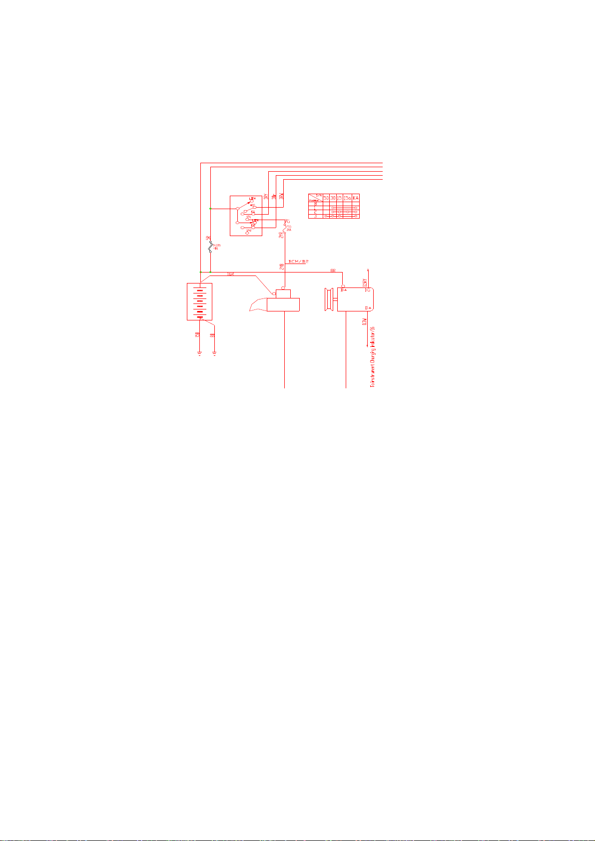
1. StartingSystem
When theignitionswitchisturnedtoSTposition, thepull-inwindingofthestarterpowerson, and
thenthestartinggearofstatermotorispushedtoand engagedwiththegearofflywheel.Atthe
sametime,whenthegearsengage,thecontacton thepull-inwindingworksandconnectsthe
powersupplyfromthebatterytothestartermotorsoastoturnthemotorand startuptheengine.
WhentheignitionkeyreturnsbacktotheIGposition,theholding coilofthestarterpowersoff,
and undertheactionofspringforce ofthegearthemotordisengagesfromtheflywheelandthe
flywheelofstartermotordisconnectsatthesametime.ThestartingsignalistransmittedtoBCM
atthesametime.TheBCMutilizesthestartingsignaltodeterminethatthesystemisinthe
starting condition.Inthiscase,theBCMwill stoptheactionofmotorofwindowglass regulator
soastoensurethatthereiselectricengergyenoughtobesuppliedtostartermotor.
2. ChargingSystem
WhentheignitionswitchisinIGposition,thepowersupplyfromtheignition switchF17 isused
toexcitethegeneratorsoastoensurethatit cangenerateelectricpowerduringthegeneratoris
AtBody
At
Transmission
Ignition
Switch
Battery
Starter
Generator
30
30a
15
15a
Ka
Ignition Switch
To Fuse F17

operating.Whenthegeneratoritselfcangenerateelectricpower,thesystemwillswitchtothe
self-excitationmode.Inaddition,whenthegeneratorisgeneratingelectricpower,it givesasignal
totherelevantinstrumentviatheD+ terminal.Aftertheinstrumentreceivethesignalfromthe
generator, thebatteryindicatorontheinstrumentwillbeextinguished.
3.Troubleshootingand Elimination
3.1.Thestarternotoperate, lowpoweroutputoritsfuseburnout
Notoperate: Whenthekeyisinstartingposition,ifthesound ofaction ofpull-inwindingcanbe
heardwhilethemotordoesn toperate,thismaybecausedduetothebatteryno poweroutput,
contactinpull-inwindingfailureorstartergroundpoor.
Lowpoweroutput: Thestartercanoperatewhilewithlowpoweroutput.Thecausemaybelow
poweroutputofbattery,orhighresistance ofenginemechanicalparts.
Fuseburnout: Ifthefuseburnsoutfrequentlywhenstarting,it maybecausedduetothestarter
groundpoor,wireconnectionpoororstarterinteriorand engineinteriorresistance overhigh.
3.2.Generatornotworkorlowpoweroutput
Generatornotwork: Generator snotworking maymakeaninfluenceonmany systems, and also
result thatthebatteryisusedoutrapidly.Thecausetoresultthegeneratordoesn tworkmaybe
theexcitingcircuit workpoor,andalsomaybetherotor,carbon brushorrectificationregulator
insidegeneratorfailure.Ofcourse,thegeneratorisnowunallowabletoberepaired.If thetrouble
iscausedduetothegeneratorproblem,pleasereplacethegeneratorassy..
Poweroutputloworoverhigh: Whenthegenerator spoweroutputislow,it mayresult thatthe
systemvoltageislowandmanysystemsfail toworknormally. ForthevehicleequippedwithABS
system,theABSsystemisverysensitivetothepoweroutputofgenerator.Incasethatthepower
outputislow,thesystemimmediatelychangestothefailuremode.Themaincausetoresult the
lowpoweroutputmaybethereguatorinsidethegeneratorworkpoororgenerator sbelt looseand
etc.Thepoweroutputoverhighgenerallymeansthatthevoltageisoverhigh,whicheasily
damagestheelecticaldevices.Thisisaverydangerousfailurewhichmayresult theelectrical
harness catchesafire.Thegeneratorvoltageoverhigh ismainlycausedduetotheregulating
circuit insidethegeneratorworkpoor.

II.BCMControl
1.CeilingLampControl
lWhenanydooropens,theceiling lamplightsautomatically,andthenextighuishes15
minuteslaterafterthedooropens.
lTheignitionswitchisplacedtoOFFposition,and,8slaterafterall fourdoorsclose,the
ceilinglampgraduallyextinguishes,withdurationof2s.
lDuringtheceilinglampdelays8s,iftheignitionswitchchangesOFF positiontoON
position, theceilinglamp extinguishesimmediately.
lIf theignitionswitchisinON positionandall fourdoorsclose,afteranydooropensand
thencloses, theceiling lampimmediatelyextinguisheswithouttimedelay.
lWhenall fourdoorscloseand theceilinglamplights,press downtheLOCKbutton on
theremotecontrollerandthenthelampimmediatelyextinguishes.
lPress theUNLOCKbuttononce,thentheceilinglamplightsandkeepslightingfor8s,
and thelampextinguishesslowlywithinthesubsequent2 s.
Note:Whentheswitchof ceilinglampisplacedtothecontrolledposition,theceilinglampcontrol
functionisavailable.
2.WindowGlass UP/DOWNFunction
lTheelectricwindowcontrolisallowableonlywhentheignitionswitchisin ON position,
oronlywithin1minuteaftertheignitionkeychangesfromON toOFF,otherwise,the
electricwindowcontrolisprohibited.
lTemporarilystop theliftingofwindowglass whenstarting
lAutomatic/manualcontrol
ManualcontrolUP:Ifthedriver-sidedoororpassenger-sidedoorwindowUPswitchis
pulledup, thewindowwill bedrivenbyamotorandlift.
Note:Withouttheautomaticwindowliftfunction,onlywiththemanualliftfunction).
Automatic/manualDOWN:If theswitchinputtimet<300 ms,thewindowwill
aumaticallyfall down.Whentisgreaterthanorequalto300 ms,thewindowwill
manuallyfall down.
lPress theLOCKpushbuttonfor2severytimetoremotecontroltheliftingofwindow
glass, andreleasaethepushbuttontostoptheliftingofwindowglass.
3. CentralDoorLock
lThefrontleftdoorkeyindependentlycontroltheunlocking/lockingofthecentraldoor
lock.

lThedoorlockandwindowglass regulatorcan tactatthesametime,andtheformeris
preferredifconflict.
lAutomaticdoorlockcontrol(pre-reservedsignal,suitableforthespeedlockingof
vehicleequippedwithairbagandtheunlockingaftertheairbagexplodes).
4.Anti-theftAlarmSystem
4.1. Doorlockremotecontrolfunction
Whentheremotecontrolkey sUNLOCK/LOCKpushbuttonispresseddown,thedoor
lockmotorwill act0.6 s ±50 ms.
Whenthedoorunlocks,theright/leftturnsignallampflashes:0.5s ±50msOn;0.5s ±
50msOff;0.5s ±50msOn.Andthenit extinguishes.
Whenthedoorlocks, theright/leftturnsignallampflashes:0.5s ±50ms.
4.2. Vehiclesafety systemhasfivemodes:
ØArmingmode –WhenadriverpressesdowntheALARMbutton,thevehicleisin
armingcondition.
ØDisarmmode –Thearmingmodeisremovedbythedriver.
ØAlarmmode –Whenainvasion eventisdetected,thesystemmaygiveanalarm(not
giveanalarmforthevehiclewithoutthealarmhorn).
ØDisalarmmode –Thedriverreturnsbacktothesideofvehicleandturnsoffthealarm.
ØArming failuremode –Thevehiclefailstosuccessfullyestablishthearmingcondition.
4.3. Arming mode:
a) Howtoenterintothearmingmode:
Condition: Fourdoorsclose; ②Fronthoodand reartrunckclose.
Operation:Press downthe “LOCK”button ontheremotecontroller.
b) Representation whenenteringintothearmingmode:
Beforethebodyentersintothenormalarmingmode: theleft/rightturnsignallamp
flashesonce; ②thebodyanti-thefthorngivesanalarmonce(notgiveanalarmforthe
vehiclewithoutthealarmhorn).
c) Specificrepresentationwhenthefailuretoenterintothearming mode:
Whenthefailuretoenterintothearming mode,thesystemwill hasthefollowing
representations: theleft/rightturnsignallampcontinuouslyflashestwice; ②thebody
anti-thefthorndoesn tgiveanalarm(notgiveanalarmforthevehiclewithoutthealarm
horn).
d) Bodystateafterenteringintothearming mod:
Afterthebody entersintothenormalarmingmode: thefourdoorsarelocked; ②the

armingindicatorlightcontinuouslyflashes; ③iftheceilinglampswitchisinthe
controlledpositionandtheceilinglampisinOPENposition, theceilinglampcloses.
4.4. Disarmmode:
a) Howtodisarm:
Condition:Thebodyisinthenormalarmingmode.
Operation:Press downthe “UNLOCK”buttonontheremotecontroller.
b) Representation whendisarming:
Beforethebodychangesfromthenormalarmingmodetothedisarmmode: the
left/rightturnsignallampcontinuouslyflashestwice; ②thebodyanti-thefthorn
continuouslygivesanalarmtwice(notgiveanalarmforthevehiclewithoutthealarm
horn).
c) Bodystateafterdisarming:
Afterthebodyisdisarmed: thefourdoorscanbefreelyopened; ②thearming
indicatorlightstopsflashing; ③theceilinglampautomaticallyextinguisheswithin8s
afterit turnson.
(CAUTION:If noactiononthebodyisimplementedwithin28 safterdisarming,28 s
later,thebodycontrolmodulewillautomaticallymakethebodyenteragainintothe
armingcondition.
4.5. Alarmmode:
a) Howtotriggerthealarmmode:
Condition:Thebodyisinthenormalarmingmode.
Operation: Enfocedlyopenanyoffourdoors; ②enforcedlyopenfronthoodortrunk;
③turnontheignitionswitch.
b) Representation whenenteringthealarmmode:
Afterthebodyentersintothealarmmode: theleft/rightturnsignallampcontinuously
flashesfor28 s; ②thebody anti-thefthorncontinuouslygiveanalarmfor28 s; ③after
stoppingalarming,28 slater,iffourdoor,fronthoodand trunkcloseandthenopen,the
left/rightturnsignallampandthebodyanti-thefthornwill betriggeredfor28 s,and
cycles; ④ifthedooropenor “ignition”stateexistsatall times,thealarmisgiventen
cyclesandthenstops,withthecycleintervalof2s(notgiveanalarmforthevehicle

withoutthealarmhorn).
4.6. Disalarmmode
a) Howtodisalarm:
Afterthebodyentersintothealarmmode: pressdownanypushbuttonontheremote
controller.
b) Bodystateafterdisalarming:
1. If thetriggeredalarmdoorisinopenstate(notgiveanalarmforthevehiclewithout
thealarmhorn).
Press downtheUNLOCKpushbuttonon theremotecontrollerto disalarm; ②unlock
thecentraldoorlock.
Press downtheLOCKpushbuttonontheremotecontrollerto disalarm; ②enablethe
armingtobefailed.
2. Ifthetriggeredalarmdoorisinclosestate(notgiveanalarmforthevehiclewithout
thealarmhorn):
Press downtheLOCKpushbuttonontheremotecontrollerto disalarm; ②disarm,and
carryoutthesecondaryarmingafter28 s.
Press downtheLOCKpushbutton ontheremotecontrollerto disalarm; ②enterinto
thearmingmode.
4.7. Arming failuremode
a) If door,enginehood,trunkfail tocloseatthesametime,pressingtheArmkeycan tset
upthearmingcondition:
Afterthefailureofbodyarming: theleft/rightturnsignallamplights.
III. Fog andPositionLampsControl
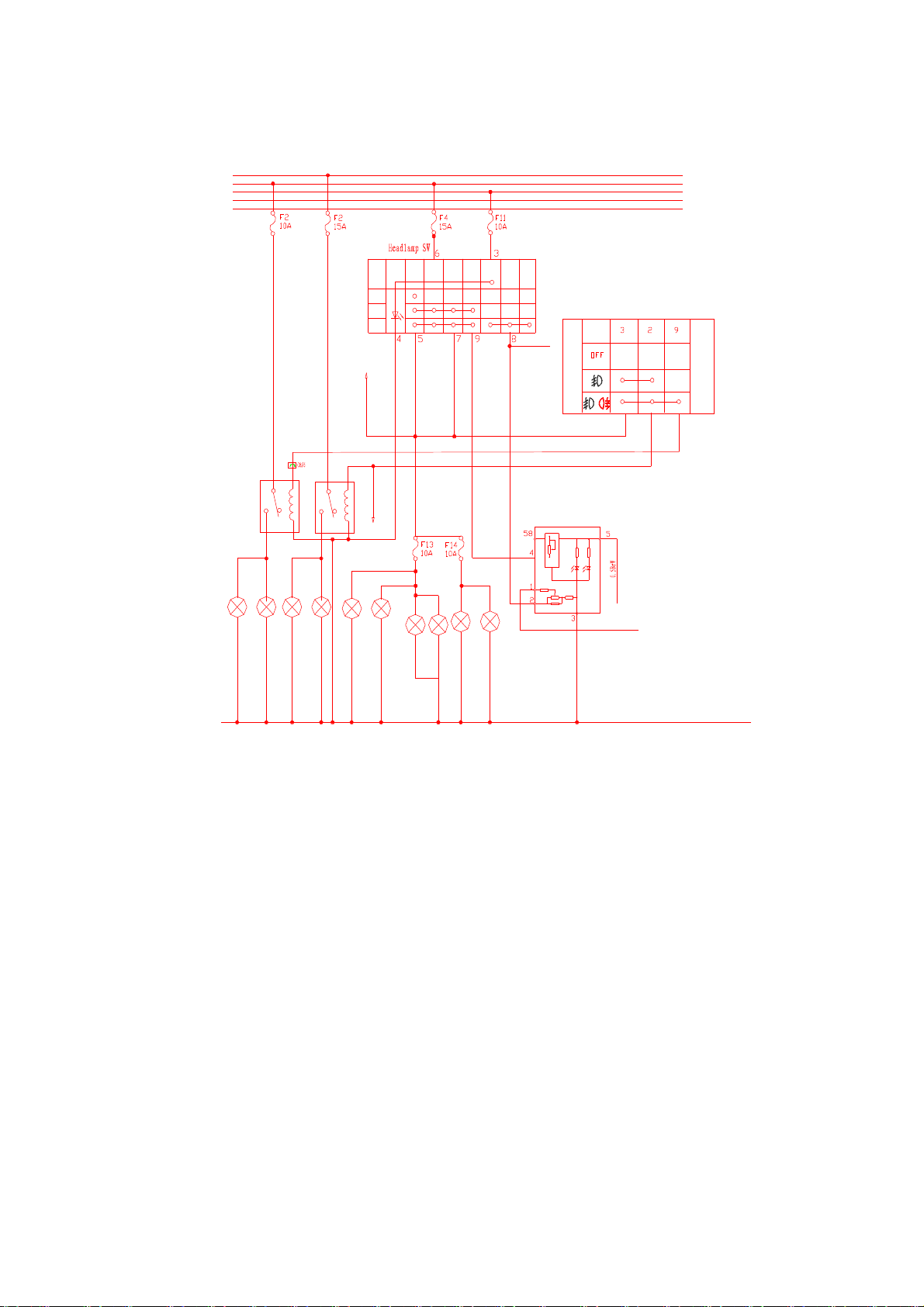
1. PrincipleofFogLampControl
Thefoglampiscontrolledbythecombinationlightswitchwhichisusedtocontroltheopen/close
ofthefog lamprelay.Whenthelightswitchisturnedtotheclearance lampposition,theelectric
powerfromthefuseF4issuppliedtothefoglampswitchviatheangle7#. Whenthefoglamp
switchisinthefrontfoglampposition,the3# terminalofthefoglampswitchissuccessfully
connectedtothe2# terminaltomakethefrontfog lamprelayengagedand thuslightupthefront
fog lamp. Whenthefoglamp switchisintherearfog lampposition, all terminals3#, 2# and 9# of
thefoglampswitchturnon,andtherearfoglamprelayalsoengages.Inthiscase,thefrontand
rearfoglampslightatthesametime.So, theprincipleofthefoglamp controlisjusttoturnonthe
clearance lamp(positionlamp)andthenturnonthefrontfoglamp,andtherearfoglampcanbe
turnedon onlyafterthefrontfoglampturnson(thisisimplementedusingtheswitch).
Terminal
Light
Control
Switch
Rear Right Tail Lamp
Right Clearance Lamp
License Plate Lamp
Front
Fog
Lamp
To
Instrument
Rear FogLamp Relay
To
Instrument
OFF
Headlamp
Power
Clearance
Lamp
15a
Ka
30a
15
30
To
Each
Night
Light
Switch
Power
Left Clearance Lamp
RearLeft Tail Lamp
Front Right FogLamp
FrontLeftFog Lamp
Rear Right FogLamp
Rear Left Fog Lamp
Clearance
Lamp
Headlamp
Front Fog Lamp Relay

2. PrincipleofClearance LampControl
Theclearance lampiscontrolledusingalightswitch.Whentheswitchisintheclearance lamp
position,theterminals5# and6# ofthelightswitchwillbeturnedontomakethepowersupply
fromthefuseF4gettotheclearance lampviatheangle5#, and thefrontandrearclearance lamps
connecttothefusesF13 andF14 respectively. Inaddition,thelicenseplatelampalsolights.
3. NightLightandElectricHeadlampControl
When thelightswitchisintheclearance lampposition,theterminals6# and 9# ofthelightswitch
areturnedon,whichsuppliestheelectricpowertotheterminal4# ofthenightlightregulating
switchandthusmakesall nightlightcircuit poweron.Surely,thebrightness iscontrolledbythe
regulationresistancemountedonthenightlightswitch.Whenthelightswitchisintheheadlamp
position,thepowersupplyfromthefuseF11isconnectedviatheangles3# and 8# ofthe
headlampswitchwhichareusedtosupplytheelectricpowertotheelectricswitchandheadlamp
relay.Inthiscase,theelectricswitchcanemployitsslideresistortocontroltheoperationof
electricmotor.So,fromtheprinciplesabove,it canbeconcludedthatthenightlightworksonly
whenthelightswitchisintheclearance lamporheadlampposition,andtheelectricheadlampcan
beadjustableonlywhenthelightswitchisintheheadlampposition.
IV. HeadlampControl
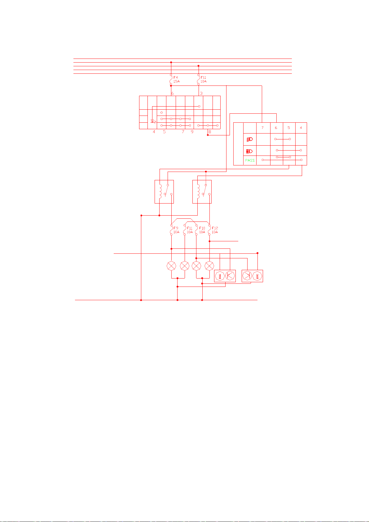
1. Principleoflowbeamlampcontrol
Whenthelightswitchisintheheadlampposition,theterminal8# ofthelightswitchoffers
thelightcontrolswitch s6# terminaltheelectricpower.Whenthelightcontrolswitchisinthe
lowbeamposition,theswitchwill turnontheterminals6# and 5# tomakethelowbeamrelay
closeandthuslightupthelowbeamlamp.
2. Principleofhighbeamlampcontrol
Whenthelightcontrolswitchisintheheadlampposition, theswitchwill connectthepower
supplyfromtheterminal8# ofthelightswitchandtheterminal4# oflightcontrolswitch,which
makesthehighbeamrelaycloseandthuslightsup thehighbeamlamp.
Right High Beam
Right Low Beam
Left High Beam
Left Low Beam
Light Switch
Light Regulating
Switch
High Beam Indicator
High Beam
Relay
Low Beam
Relay
Terminal
Light
Control
Lamp
OFF
Headlamp
Power
Clearance
Lamp
15a
Ka
30a
15
30
Power
Clearance
Lamp
Headlamp
3. Principleofthepassinglampcontrol
WhenthelightcontrolswitchisinPASS position(passinglampposition),theswitchdirectly
offersthehighbeamrelaytheelectricpowerfromthefuseF4, withoutviathelightswitch,which
lightsup thehighbeamlamp.So,it isunnecessarytoopenthelightswitchwhenthepassinglamp
isinservice.
V.TurnSignalLampControl
Rear
Right
Lamps
Rear
Left
Lamps
ToAnti-theft Module
ToInstrument
Turn
Signal
Switch
Flasher
Relay
Alarm
Switch
14
30
30a
15a
15
Ka
ToAnti-theft Module
ToInstrument
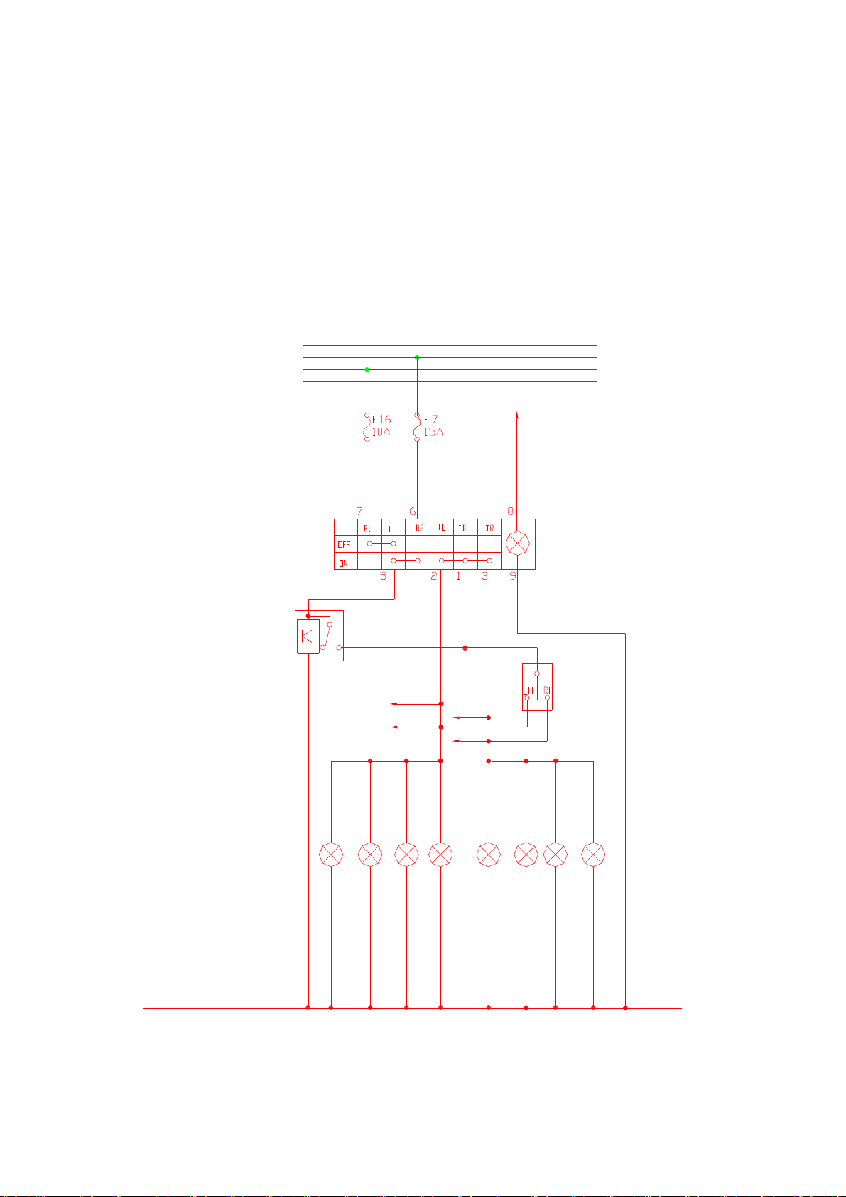
1. Principleofturnsignallampcontrol
Theturnsignallampcontrolisdividedintothree categorieswhilethefinalcontrolis
implementedbytheflasherrelay.
Alarmswitchcontrol: ThealarmswitchhasthepowersupplyfromthebatteryF7fuse.So,it
ensuresthattheswitchcanworkincasethattheignition switchdoesn tturnon.Whenthealarm
switchisinON position,theflasherrelayispoweredbytheterminals5# and 6# ofthealarm
switch.Inthiscase,theemitterelectrodeoftherelaywill provideaintermittentvoltagesignal,
and theterminals1#, 2# and 3# oftwoalarmswitchesutilizethisintermittentsignaltoturnonthe
turnsignallampand maketheturnsignallampwork.
Turnsignallampcontrol:Whenthealarmswitchisoutofservice,theelectricpowerof
flasherrelaybaseelectrodeissuppliedfromtheterminalF16 oftheignitionswitch.Incasethat
theturnsignallampswitchturnsontheleftorrightcircuit,theintermittentpowersupplyfrom
flasherrelaywill enablethecorresponding turnsignallamptowork.So,theturnsignallamp
controlisjustthedirectswitchcontrol.
BCMcontrol: Forthesakeofbodyanti-theftrequirement,theturnsignallampisrequiredto
workwhenremotecontrolofarmingandtheelimination ofanti-theft.So,BCMalsocontrolsthe
turnsignallamp.Thiscontrolisnotviathealarmandturnsignalswitches,and itsintermittent
signalisimplementedwithitsinternalcircuit.
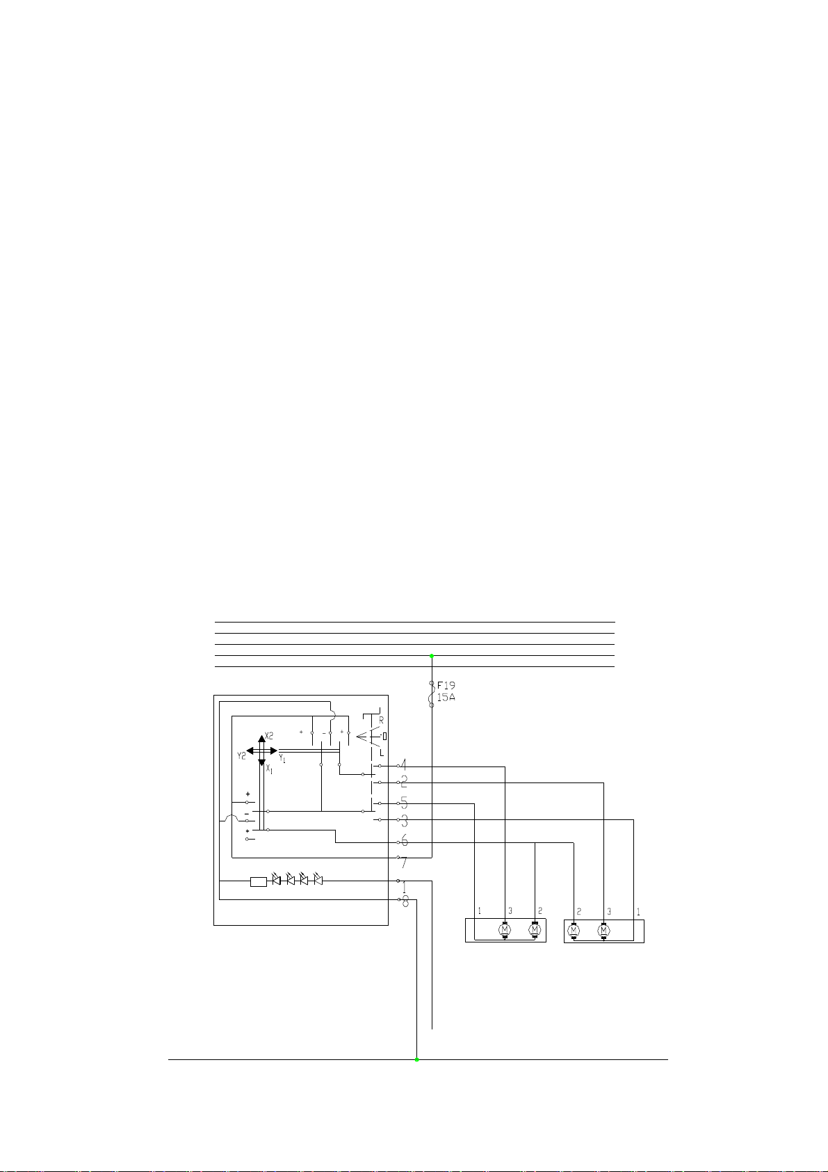
VI. ElectricRear-ViewMirror
30
30a
15
15a
Ka
To
Night
Light
Right Rear-View
Mirror Left Rear-View
Mirror

1. Controlprinciple
Theelectricrear-viewmirrorr iscontrolledbyaswitch,withoutanyrelay.WhentheL
positionisselected,theNos2and 3circuitsformalooprespectivelywiththeinternalcircuit of
theswitch.TaketheY1directionasanexample,whenpushingtheswitchintheY1direction,the
switchconnectstothepowersupplyfromF19 whilethepowersupplyconnectswiththeNo2
circuit (withNos2 and 3 circuitswhentheswitchisinLposition). So, thecurrentflowsacross the
motor,goesthroughNo3circuit andthengetstotheground.Similarly,whentheswitchisinR
position, theNos4 and5 circuitsconnecttothecorrespondingcircuit andformaloop.
VII.WiperMotorControl
Wiper Intermittern Relay
FrontWiper
Motor
Front
Washer
Motor
WASHERHIGHLOW
FRONT
RETURN
POWER
WIPER SWITCH
09
Ka
15a
15
30a
30
POWER

1. Controlprinciple
Thiswipersystem scontrolisaswitchtypeonewhiletheintermittencontroladoptsthe
intermittenrelay.Thewipermotorisgroundeditself.WhentheswitchisintheLowSpeed
position,thewiperswitchisusedtoconnectthepowersupplyfromF19 withtheNo1terminalof
thewipermotor,andthewiperstartstooperateatlowspeed.WhentheswitchisintheHigh
Speedposition,thewiperswitchisemployedto connectthepowersupplyfromF19 withtheNo2
terminalofwipermotorsoastoenablethewipermotortooperateathighspeed. Whentheswitch
isintheIntermittentposistion,thewiperswitchisusedtoconnectthepowersupplyfromF19
withtheNo7terminaloftheswitch,whichoffersthebaseelectrodeoftriodeofintermittentrelay
thepowersupply.Thetriodecontrolstheinternalswitchestomakethepowersupplyofwiper
motor3gothroughNo4circuit andviatheintermittenrelaycontrolledswitchandthengettothe
wiperswitch6. Then, through thelowspeedcircuit, thewipermotorisintermittentlycontrolled.
2.Wiperreturnandstop function
Inordertoensurethatthewipercanreturnbacktoitsoriginalpositionwhenthewiperstops
working,therearetwosetsofcontactmechanismsinsidethewipermotor:oneisreturncontact,
and theotherisstopcontact.Whenthewiperoperatesatloworhighspeed,bothsetsofcontacts
areoutofservice.However,whentheloworhighspeedpowersupplyofthewiperdisconnects,
thewipermotorispoweredbytheNo3powersupplyofmotorandkeepscontinuousoperation.
Whenthemotoroperatestothespecifiedposition (thewiperbladereturnsbacktotheoriginal
position),theNo3powersupplyofwipermotorisdisconnectedwhiletheNo4appliesthepower
supplyfromF19 onthenormallowlevelsideofthewipermotorbyturningontheintermittent
relayswitch.Inthiscase,it enablethemotortoproduce thetrendofrotationin reverse.Thistrend
justcounteractsthemovementofwipermotorgeneratedduetotheinertiaafterpoweroff,which
makesthemotorbrakedimmediatelyandstopoperation.

ChapterTwoSchematic DiagramsofCircuit Control
I.Definition ofMainHarnessConnectors
/前( 动机线束和前仓线束插接件)
前/仪(前仓和仪表线束的 插件)
前/仪 (前仓和仪表线束的 插件)
Engine/Compartment(Engine andCompartmentHarness sConnector)
Compartment/InstrumentA(CompartmentandInstrumentHarness sAConnector
Compartment/InstrumentB (CompartmentandInstrumentHarness sB Connector)

前/室(前仓和室内线束的插件)
针脚定义
针脚定义
室/仪(室内线束和仪表线束的插件)
Compartment/Interior(CompartmentandInteriorHarness sConnector)
Interior/InstrumentB (InteriorHarnessandInstrumentHarness sAConnector)
Definition ofECUPin
Definition ofABSPin

室/仪(室内线束和仪表线束的插件)
室/左前 (室内线束和左前门线束的插件)
室/左前(室内线束和左前门线束的插件)
室右前(室内线束和左前门线束的插件)
室/左后(室内线束和左后门线束的
插件)
Interior/InstrumentA(InteriorHarnessandInstrumentHarness sAConnector)
Interior/FLA(InteriorHarnessandFrontLeftDoorHarness sAConnector)
Interior/FLB (InteriorHarnessandFrontLeftDoorHarness sB Connector)
Interior/FRA(InteriorHarnessandFrontRightDoorHarness sConnector)
Interior/RLA(InteriorHarnessandRearLeftDoorHarness sAConnector)

室/左后(室内线束和左后门线束的插件)
室/右后(室内线束和右后门线束的插件)
室/右后(室内线束和右后门线束的插件)
室/后(室内线束和后背门线束的插件)
(插头阵脚定义)
Interior/RLB (InteriorHarnessandRearLeftDoorHarness sB Connector)
Interior/RR B (InteriorHarnessandRearRightDoorHarness sB Connector)
Interior/RR A(InteriorHarnessandRearRightDoorHarness sAConnector)
Interior/B (InteriorHarnessandBackDoorHarness sConnector)
BCMA(BCMAConnectorPinDefinition)
Other manuals for QQ6
3
Table of contents
Other Chery Automobile manuals

Chery
Chery SQR7240T User manual

Chery
Chery TIGGO User manual

Chery
Chery QQ3 User manual

Chery
Chery QQ6 User manual

Chery
Chery A5 2007 Service manual

Chery
Chery A113 User manual

Chery
Chery A3 User manual

Chery
Chery Tiggo 5 T21 User manual

Chery
Chery T21 2014 User manual

Chery
Chery A11 2003 Operating instructions

Chery
Chery A21 2005 User manual

Chery
Chery S18D User manual

Chery
Chery M16 Arrizo 7 2014 User manual

Chery
Chery SQR480ED User manual

Chery
Chery Automobile User manual

Chery
Chery A1 2009 User manual

Chery
Chery RIICH 2 series User manual

Chery
Chery A1 2008 Instruction Manual

Chery
Chery Automobile User manual

Chery
Chery QQ User manual


